Menu


Modified on
Understanding the failure behavior of a plate

Skill-Lync
When designing an automobile or mechanical component, engineers pay a lot of attention to the type of material that they select. Depending largely on the forces the component frequently experiences, a range of materials are chosen and after testing each material, the best fit is determined. With the rise of computational engineering, materials are first tested in simulations before they are tested using prototypes. In this project, we will be designing a component and simulate the impact on it to understand how the material reacts during collision.
Main Objective
The objective of this project is to analyze the failure behavior of the plate along with the failure card. We used the Johnson-Cook Elasto-Plastic material model (Law-2) in this project. Upon simulating the collision, we will study how the material fails under stress.
Model setup
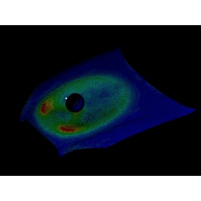
Before proceeding with the simulation, we will set up the punch and the plate. The punch is designed with a mass of 5 gms. It is made to impact the plate by defining an Imposed Velocity card. The Imposed Velocity refers to the velocity with which the punch moves towards the plate.

Punch and plate setup

Imposed Velocity Card
Defining a failure card
A failure card is used to define the failure criteria for the components. The failure card without the crack formulation is defined in the CASE-1 and the failure card along with the crack is defined in CASE-2. This helps in understanding which setting gives more realistic results. When the elements exceed the failure criteria mentioned, they get deleted. We will compare the behavior of each material with and without a failure card.
CASE-1 (without crack formulation)
The model has both the Johnson failure card as well as EPS_p_max value, with XFEM value as 0.
Xfem = 0
EPS_p_max = 0.151.
Ifail_sh = 2
When the stress and strain levels reach 15% of plastic strain, the elements fail.
For Shell elements, in each integration point, the stress in the layer is set to zero. When the stress reaches the last layer, the elements get deleted.
CASE-2 (with crack formulation)
The model has both the Johnson failure card as well as EPS_p_max value, with XFEM value as 1.
Xfem = 1
EPS_p_max = 0.151.
Ifail_sh = 1
When the stress and strain level reaches 15% of plastic strain, the elements fail.
For shell elements, when the stress reaches the one integration point, the elements get deleted.
Defining the Elastic-Plastic Strain
The Elastic-Plastic Strain (EPS_max) is used to define the failure criteria for the material. Here in CASE-3, the EPS_max value is defined and in CASE-4, the EPS_max value is not defined.
CASE-3 (with EPS value)
EPS_p_max = 0.151.
The model has only EPS_p_max value and no Johnson failure card. So, the elements fail and get deleted when stress causes 15% of plastic strain.
CASE-4 (without EPS value)
The model has no EPS_p_max value and Johnson failure card.
Material Property
The material we will be testing is LAW – 2 (Elasto-Plastic Material). The properties of the card are as follows:
Initial density (rho) = 0.0028 g/mm3
Young’s Modulus (E) = 71000MPa
Poisson’s Ratio (nu) = 0.33
True yield stress (a) = 290MPa
Hardening Modulus(b) = 562.3
Hardening exponent (n) = 0.63
Maximum plastic strain for failure (EPS_p_max) = 0.151
Maximum stress (sig_max0) or UTS = 425MPa
Observation
We observed the behavior of the material in 4 different cases:
CASE-1 vs CASE-2 (With and without defining crack formation)

1.The elements are DELETED(CASE-1) 2.The elements are CRACKED(CASE-2)
From the above images of CASE-1 & CASE-2, the deletion and the cracking of the element is seen clearly.
- The elements in CASE-1 fail rapidly when compared to the elements in the CASE-2 is because of the XFEM crack formulation. The XFEM crack formulation denotes the level at which the crack should happen.
- The reason for this lag in deletion is that the elements in CASE-2 are cracked before they are deleted, whereas in CASE-1, they are directly deleted.
- In CASE–1 the energy dissipated through the shattering of the element is because of EPS_max.
- In CASE–2 the energy is dissipated through the cracks (at the last element row).

- The internal energy of the plate increases linearly due to the absorption of the kinetic energy from the impacting sphere.
- When deformation or cracking occurs, some energy is lost. When simulating such behavior, this energy is not captured accurately. Hence, there is a difference between the energy levels of the system before and after deformation. This energy that is not captured is called hourglass energy. When performing simulations, our objective is to keep this hourglass energy at minimum levels. The hourglass energy in this scenario remains zero because the physical stabilization of the hourglass energy is achieved through the element formulation.
- We also define a contact between the two surfaces. This contact is created between the master and slave nodes. When the two surfaces come into close contact, the contact energy will act to simulate deformation. If we do not define contact, the two surfaces will penetrate each other. In our project, the contact energy levels remain at zero.

- Since the elements are shattering with high velocity in CASE-1, there is a hike in the kinetic energy curve. When compared with CASE-1, the graph denoting the cracking in the elements is a bit smoother in CASE-2. The hike in the graph denotes the deletion of a big chunk of elements from the system.
CASE-3 vs CASE-4 (With and without defining EPS value)

CASE-3 CASE-4
- The elements in the CASE-3 gets deleted when they reach the failure plastic strain to one integration point.
- The elements in CASE-4 are not deleted when they reach the maximum plastic stress to the last integration point due to the impact, since no failure card is defined.

- The internal energy of the plate increases linearly due to the absorption of the kinetic energy from the impacting sphere.
- The Hourglass and the Contact energy remains zero because the physical stabilization of the hourglass is achieved through the element formulation.

- The graph contains some noise in it since the elements getting deleted. The hike in the graph denotes a big chunk of elements getting deleted from the system.
- In CASE – 4, the kinetic energy is gradually increasing because, during impact, the elements get stretched steadily.
Conclusion:
Thus, we were able to analyze the failure behavior of a material in different cases. Considering the performance of the material during the collision, this material is suitable for real-life scenarios. We can employ the same procedure to analyze the failure behavior of other materials such as brittle plastic, elastic material, etc., and decide on the best material for a particular piece of equipment.
Author

SarangarajanV
Author
Skill-Lync
Subscribe to Our Free Newsletter

Continue Reading
Related Blogs
Explore the fundamentals of vehicle dynamics and ultimate trends in the field from design and modeling to control with Skill Lync's exclusive course on the subject. Read about how Skill-Lync's CAE courses can help you get employed.
28 Jul 2020
In this article, we will briefly discuss the working, applications, and features of the one-dimensional systematic simulation tool, GT-Power, in Emission Control Strategy, engine calibration, hybrid vehicle modeling. Read about how Skill-Lync's CAE courses can help you get employed.
28 Jul 2020
This article offers a brief introduction to the globally accepted standard of Geometric Dimensioning and Tolerancing, and its importance for the entire manufacturing process. Read about how Skill-Lync's CAE courses can help you get employed.
28 Jul 2020
In this blog we will read about Going a step into Biomechanics and how Skill-Lync's CAE course will help you get employed.
09 May 2020
The powertrain is the most prominent source of vibrations that affects the driving experience for the people on board. This blog from Skill-Lync examines these vibrations to help enhance that experience.
21 Aug 2020
Author
Skill-Lync
Subscribe to Our Free Newsletter
Continue Reading
Related Blogs
Explore the fundamentals of vehicle dynamics and ultimate trends in the field from design and modeling to control with Skill Lync's exclusive course on the subject. Read about how Skill-Lync's CAE courses can help you get employed.
28 Jul 2020
In this article, we will briefly discuss the working, applications, and features of the one-dimensional systematic simulation tool, GT-Power, in Emission Control Strategy, engine calibration, hybrid vehicle modeling. Read about how Skill-Lync's CAE courses can help you get employed.
28 Jul 2020
This article offers a brief introduction to the globally accepted standard of Geometric Dimensioning and Tolerancing, and its importance for the entire manufacturing process. Read about how Skill-Lync's CAE courses can help you get employed.
28 Jul 2020
In this blog we will read about Going a step into Biomechanics and how Skill-Lync's CAE course will help you get employed.
09 May 2020
The powertrain is the most prominent source of vibrations that affects the driving experience for the people on board. This blog from Skill-Lync examines these vibrations to help enhance that experience.
21 Aug 2020
Related Courses