What is FEA? A Beginner's Guide to Finite Element Analysis, with a Worked Example
Finite element analysis predicts how parts respond to loads, heat and vibration by splitting them into small elements and solving the equations on a computer. Here is how it works, a hand-solved example, the analysis types, and how engineers check the results.
 Skill-Lync·Updated 17 Oct 2026·11 min read
In short
- Finite element analysis (FEA) predicts how a part or structure responds to loads, heat or vibration by splitting it into many small elements and solving a large set of equations on a computer.
- The finite element method (FEM) is the mathematics; FEA is the engineering use of it. Each element behaves like a spring, and the solver assembles them into one system
[K]{u} = {F}.- A typical analysis follows seven steps: question, geometry, materials, mesh, loads and boundary conditions, solve, then verify and validate.
- FEA answers are approximate. Mesh studies, hand calculations and test data are what make a result trustworthy.
What is finite element analysis?
Finite element analysis is a numerical method for predicting how physical objects behave: how much a bracket bends under load, where a crankshaft is most stressed, at what frequency a battery tray vibrates, how hot a brake disc gets. The governing equations of solid mechanics and heat transfer are well known, but for a real shape with real loads they cannot be solved exactly by hand. FEA gets around that by dividing the object into a finite number of small, simple pieces called elements, connected at points called nodes. Inside each element the behaviour is approximated with a simple function, and the computer solves for the unknown values at every node at once.
The two terms are often used interchangeably. Strictly, the finite element method (FEM) is the mathematical technique, and finite element analysis (FEA) is its application to engineering problems with software such as Ansys Mechanical, Abaqus, Altair OptiStruct, MSC Nastran, LS-DYNA or SolidWorks Simulation.
FEA sits alongside hand calculations and physical testing. Hand calculations are fast but only work for simple shapes. Tests are the ground truth but slow, expensive and only measure where you put a sensor. FEA fills the gap: it gives the full stress and deformation field for a design that does not exist yet, so engineers can compare options and fix weak spots before cutting metal.
How FEA works: a worked example you can do by hand
The easiest way to understand FEA is to solve a tiny model yourself. Take a stepped steel bar fixed at one end and pulled with 10 kN at the other. We model it with two elements and three nodes.
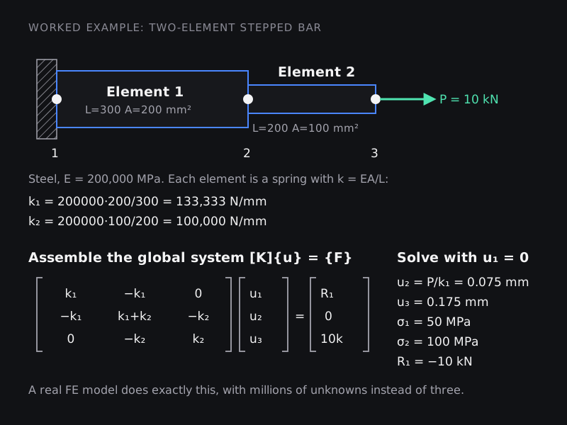
- Element stiffness. An axial bar element behaves like a spring with stiffness
k = EA/L. With E = 200,000 MPa: element 1 (L = 300 mm, A = 200 mm²) has k₁ = 133,333 N/mm; element 2 (L = 200 mm, A = 100 mm²) has k₂ = 100,000 N/mm. - Element equations. Each spring relates the forces at its two nodes to their displacements through a 2 × 2 matrix,
k [1 −1; −1 1]. - Assembly. Node 2 is shared, so its stiffness is the sum k₁ + k₂. Placing both element matrices into one 3 × 3 global matrix gives the system
[K]{u} = {F}shown in the diagram. - Boundary conditions. Node 1 is fixed (u₁ = 0), which removes the first row and column and leaves two equations in two unknowns.
- Solve. u₂ = 0.075 mm and u₃ = 0.175 mm. (Element 1 carries the full 10 kN, so u₂ = P/k₁; element 2 adds P/k₂ = 0.1 mm.)
- Post-process. Strain is the change in length over the original length; stress is E × strain. Element 1: 0.075/300 × 200,000 = 50 MPa. Element 2: 0.1/200 × 200,000 = 100 MPa. The reaction at the wall is −10 kN, which balances the applied load.
Those are exactly the answers you would get from P/A, because a uniform bar segment under end loads is something a bar element represents perfectly. A real FE model does the same steps with 2D or 3D elements and millions of unknowns: compute each element's stiffness, assemble, apply boundary conditions, solve the big system of equations, and recover strains and stresses from the displacements. If you want to see where the element matrices come from, our technical post deriving the finite element equations builds the same stepped bar from the principle of minimum potential energy.
When the elements cannot represent the answer exactly
Now make the bar taper smoothly from 200 mm² to 100 mm² over 500 mm. The exact elongation under 10 kN is PL·ln(A₀/A₁) / (E(A₀ − A₁)) = 0.1733 mm. Model it with uniform elements, each using the area at its midpoint:
| Number of elements | Elongation (mm) | Error |
|---|---|---|
| 1 | 0.1667 | −3.8% |
| 2 | 0.1714 | −1.1% |
| 4 | 0.1728 | −0.28% |
| 8 | 0.1732 | −0.07% |
| 16 | 0.1733 | −0.02% |
Each halving of element size cuts the error by about four times. This is convergence, and it is the central idea behind meshing: the answer approaches the exact solution as the mesh is refined, and the model is slightly too stiff until it does. Our article on why meshing matters shows the same effect in a bending problem and how element type changes it.
The FEA workflow, step by step
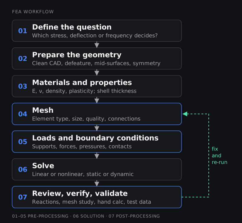
1. Define the question
Decide which output decides the design: peak stress against yield or fatigue limits, deflection against a stiffness target, the first natural frequency against an excitation, or temperature against a material limit. The question decides how much detail you need.
2. Prepare the geometry
CAD models carry detail that does not affect the answer but makes meshing hard: tiny fillets, logos, threads, small holes far from the loads. Engineers remove these (defeaturing), extract mid-surfaces for thin-walled parts that will be meshed with shells, and use symmetry to cut model size where the geometry and loads allow.
3. Materials and properties
For a linear steel analysis you need Young's modulus and Poisson's ratio (and density for dynamics). Plastics, rubber, composites and anything that yields need more: stress-strain curves, hyperelastic or orthotropic models. Shell elements need a thickness; beams need section properties.
4. Mesh
Choose element types (beam, shell or solid; linear or quadratic) and sizes, refine where stresses change quickly, and check element quality. This step usually takes most of an analyst's time.
5. Loads and boundary conditions
Supports, forces, pressures, bolt pretension, temperatures and contacts between parts. This is where most wrong answers come from: a support that is stiffer than reality, a load applied at a single node, or a missing contact can change results more than any mesh refinement.
6. Solve
The solver assembles and solves the equations. Linear static problems are solved in one step. Nonlinear problems (large deformation, plasticity, contact) are solved in increments with iterations, and dynamic problems are solved in time steps, either implicitly or explicitly. See our guide to implicit vs explicit FEA for when each is used.
7. Review, verify and validate
Contour plots are the start of the review, not the end. The checks in the next sections are what turn a coloured picture into an engineering result.
Types of FEA analysis
| Analysis type | What it answers | Typical example |
|---|---|---|
| Linear static | Stress and deflection under steady loads, assuming small deformation and linear-elastic material | Bracket, mounting, frame under service load |
| Nonlinear static | Behaviour with large deformation, yielding (plasticity) or contact between parts | Snap-fits, seals, bolted joints, permanent set after overload |
| Modal | Natural frequencies and mode shapes | Keeping a battery pack or bracket away from road and motor excitation |
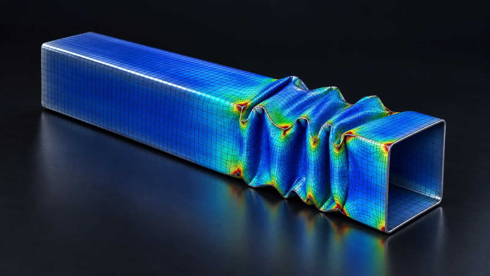
| Linear buckling | Load at which slender or thin parts suddenly lose stability | Columns, thin-walled tubes, panels under compression |
| Harmonic and random vibration | Response to steady sinusoidal or random excitation | Electronics on a vehicle, engine-mounted components |
| Transient dynamic (implicit) | Response over time to time-varying loads | Suspension events, machinery start-up |
| Explicit dynamics | Very short, violent events with large deformation and contact | Crash, drop tests, impact, forming |
| Thermal (steady or transient) | Temperature distribution and heat flow | Brake discs, power electronics, battery modules |
| Thermo-mechanical | Stresses caused by temperature changes | Exhaust manifolds, welded assemblies, PCBs |
| Fatigue | Life under repeated loading, from FE stresses | Suspension arms, crankshafts, welded chassis joints |
The finite element method is also used for electromagnetics, acoustics and coupled multiphysics problems. Fluid flow is usually solved with the finite volume method instead; our guide to CFD explains the difference.
Linear vs nonlinear FEA
A linear analysis assumes three things: deformations are small, the material stays elastic, and contacts and supports do not change during loading. Under those assumptions, doubling the load doubles every result, and the solution takes one step. It is fast and is the right first analysis for most parts.
When any assumption fails, the problem becomes nonlinear: geometric nonlinearity (large deflections or rotations, buckling), material nonlinearity (yielding, rubber), or boundary nonlinearity (contact opening and closing, friction). The solver then applies the load in increments and iterates within each one, typically with the Newton-Raphson method. Nonlinear models take longer and need more judgement, but they are the only way to predict permanent deformation, ultimate strength or the behaviour of rubber parts.
How to check an FEA result
An FEA result is only as good as its checks. Engineers separate two questions, a distinction formalised for solid mechanics in ASME's V&V 10 standard:
- Verification: are the equations being solved correctly? This covers the mesh study, the solver's own warnings and the model's internal consistency.
- Validation: are they the right equations for reality? This means comparing with test data or field experience.
A practical checklist before you share any result:
- Units are consistent (for example mm, N, MPa, tonne). A wrong density unit is a classic modal analysis mistake.
- Reaction forces balance the applied loads. If you applied 10 kN, the supports should report 10 kN.
- The deformed shape makes sense when animated at an exaggerated scale.
- A hand calculation agrees within a sensible margin (beam bending, P/A, pressure vessel formula).
- The mesh is converged for the stress you report, and peak stresses are not sitting on a singularity such as a sharp corner or a point load.
- The assumptions are written down: what is linear, what is fixed, what was simplified.
Where FEA is used
- Automotive: body-in-white stiffness, durability of chassis and suspension parts, crash, NVH, battery pack structures.
- Aerospace: airframe stress, composite laminates, engine components, certification analyses.
- Civil and structural: buildings, bridges and foundations, usually with design-code checks on top of the analysis.
- Industrial equipment and energy: pressure vessels, piping, turbines, wind turbine blades.
- Electronics and consumer products: drop tests, thermal stresses in boards and solder joints, snap-fits.
- Biomedical: implants, stents and prosthetics.
FEA software you will come across
General-purpose solvers include Ansys Mechanical, Abaqus, MSC Nastran and Simcenter Nastran, and Altair OptiStruct. LS-DYNA, Abaqus/Explicit and Radioss are the common explicit codes for crash and impact. HyperMesh and ANSA are the dominant pre-processors in automotive CAE. CAD-embedded tools such as SolidWorks Simulation are a good place for designers to start. Learn the fundamentals and one solver properly; switching tools later is mostly a matter of menus.
A short history of FEA
- 1943: Richard Courant published variational methods for problems of equilibrium and vibrations, using piecewise approximations over triangular regions, an early mathematical root of the method.
- 1956: Turner, Clough, Martin and Topp published "Stiffness and Deflection Analysis of Complex Structures" from aircraft structures work at Boeing, setting out the direct stiffness approach used in the example above.
- 1960: Ray Clough introduced the name "finite element method" in a paper on plane stress analysis.
- Late 1960s to early 1970s: NASA sponsored NASTRAN, a general-purpose structural analysis program for static, buckling, vibration and transient analysis, which grew into the commercial Nastran codes still used today.
Limitations of FEA
- Garbage in, garbage out. Wrong loads, supports or material data give confident, wrong answers.
- It is approximate. Results depend on mesh, element type and modelling choices, so they must be checked.
- Real-world variability such as weld quality, residual stresses, manufacturing tolerances and material scatter is hard to model and often handled with safety factors.
- Some problems are expensive: nonlinear, contact-heavy and explicit models can take hours or days.
- It does not replace testing for certification; it reduces the number of tests and explains what they show.
How to start learning FEA
- Revise strength of materials: stress, strain, bending, torsion, buckling, stress concentrations. FEA only amplifies what you understand.
- Solve small problems by hand or in code, like the stepped bar above, then a 2D truss. Writing a few dozen lines of MATLAB or Python that assemble and solve a stiffness matrix removes the mystery from commercial solvers.
- Learn one solver and one pre-processor properly. The Basics of FEA: Explicit and Implicit FEA course covers the theory, Structural Analysis using Ansys Workbench covers a mainstream solver, and FEA using SolidWorks is a gentle start for designers.
- Practise meshing and checking, since that is what employers test first.
- Build projects you can defend: two or three analyses with mesh studies and hand-calculation checks are worth more than many unchecked contour plots. The PG Program in CAE brings these together with industry projects.
Frequently asked questions
What is the difference between FEA and FEM?
FEM, the finite element method, is the numerical technique. FEA, finite element analysis, is the use of that technique to analyse engineering problems, usually with commercial software. In everyday conversation they mean the same thing.
What is the difference between FEA and CFD?
FEA is mostly used for solids: stress, deformation, vibration and heat conduction. CFD (computational fluid dynamics) solves fluid flow and heat transfer in fluids, usually with the finite volume method. Many products need both, for example mapping CFD temperatures or pressures onto an FEA model.
Is FEA hard to learn?
Running the software is not hard; getting answers you can defend is. Most of the learning is in meshing, boundary conditions and checking results. A solid base in strength of materials makes everything easier.
Which FEA software should a beginner learn first?
Pick a tool used in the industry you are targeting: Ansys Mechanical and Abaqus are widespread; HyperMesh with OptiStruct or Nastran, and ANSA, are common in automotive; LS-DYNA dominates crash. The concepts transfer between them.
How much maths do I need for FEA?
To use FEA well you need matrices, basic calculus and solid mechanics. To develop elements or solvers you need numerical methods, variational calculus and continuum mechanics.
Can FEA replace physical testing?
Not completely. FEA reduces the number of prototypes and tests and explains their results, but tests remain the reference for validation and certification.
Sources and further reading
- R. Courant, Variational methods for the solution of problems of equilibrium and vibrations, Bulletin of the American Mathematical Society 49 (1943) 1–23
- M. J. Turner, R. W. Clough, H. C. Martin and L. J. Topp, Stiffness and Deflection Analysis of Complex Structures, Journal of the Aeronautical Sciences 23(9) (1956) 805–823
- NASA Technical Reports Server, The NASTRAN computer program for structural analysis
- ASME, V&V 10: Standard for Verification and Validation in Computational Solid Mechanics