Week 9 - Project 1 - Door Trim Lower with Engineering Features
Aim - To create the Door Trim Lower Plastic component through the given Class-A surface.
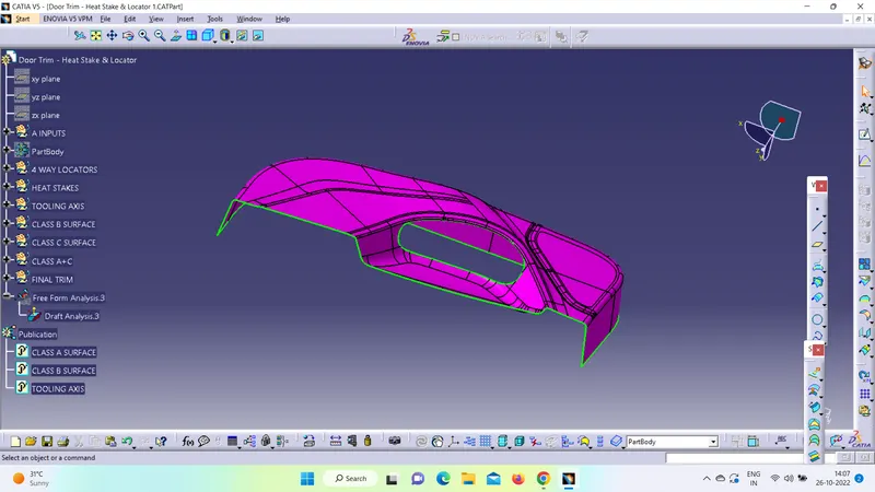
DESIGN METHODOLOGY - We have to follow the procedure for designing door trim plastic component which is given below:
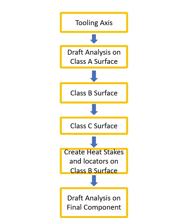
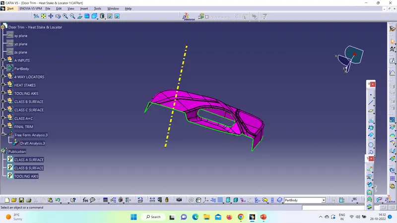
1. Tooling Axis - We will create the tooling axis for the given component by below steps:
- The first step is to ensure that the given surface is a closed surface. This can be fixed by using the join option. For verification use the join tool or the boundary tool.
- An axis for the tooling direction is decided through visual inspection.
- The tooling direction in this model will be created paralell to the Y direction. For this a point is inserted at the centre of gravity and a line is created parallel to the X direction through the point.
- This line will be the tooling axis.
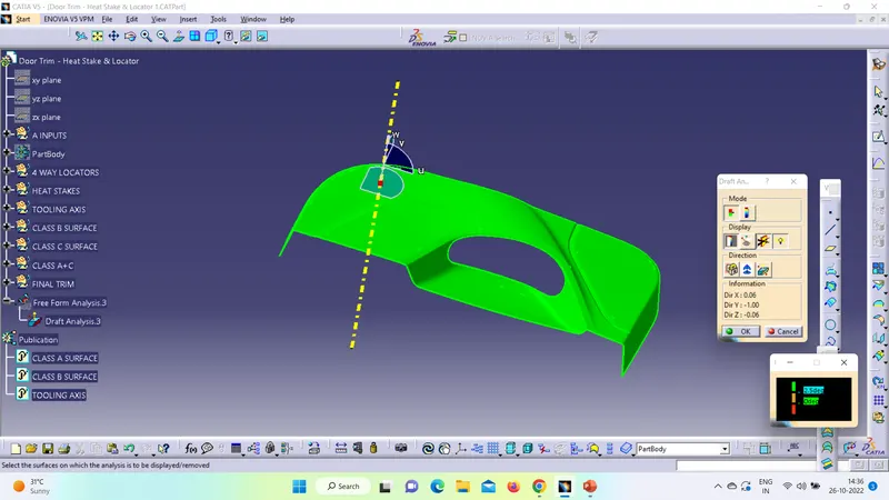
2. Draft Analysis on Class A Surface - We do perform the draft analysis check for class A surface before we make solid and creation of B-side features. Initially we align the compass to the tooling axis and we gave a 2.5deg draft angle for the green colour in the colour bar. If the surface is highlighted in green colour the draft angle is given properly for class A surface. If the class A surface is not highlighted fully in green colour, then we need to coorect the tooling direction.
3. Class B Surface - Now, we create the Class B Surface by taking an offset of 2.5mm in the downward direction but meanwhile an offset it will show a dialog box which states offset have to be created without the subelements. Click on O.K. and then offset will appear with some errors or gap which is shown below:
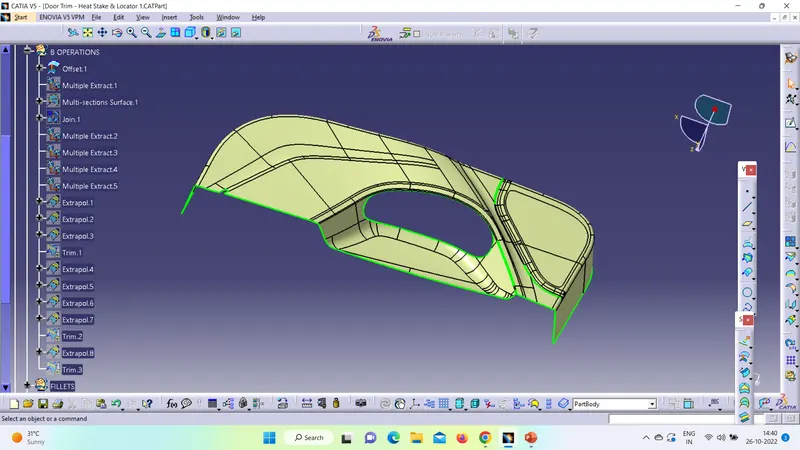
By enabling Surface Boundaries in Tools<Option<Visualization. All open boundaries will be highlighted in green color as shown above.
Now, remove all the gap by using below tools:
- Multiple extract
- Extrapolate
- Trim
- Edge Fillet
- Multi Section Surface
After using all above tools in right direction we will get the required Class B Surface as shown below:
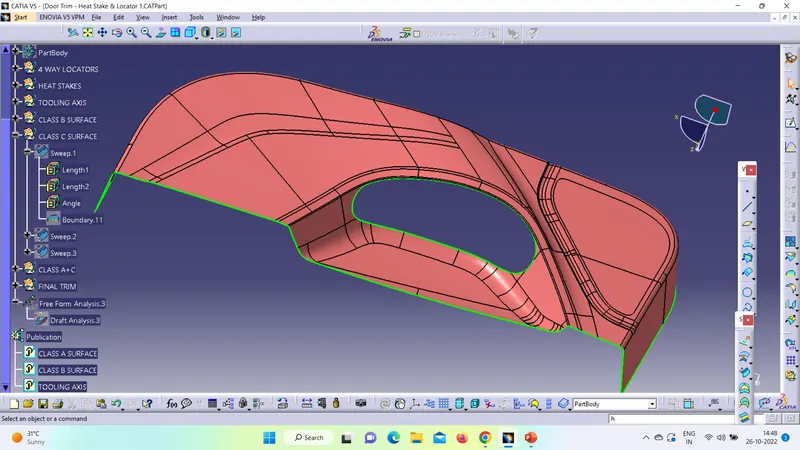
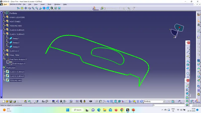
4. Class C Surface - Now, we will create the class c surface by using Sweep<Line<With reference surface, with respect to Class A Surface as shown below:
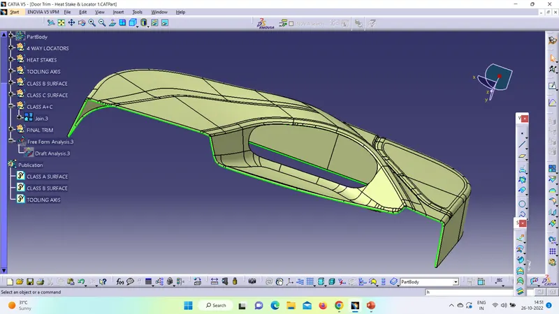
5. Class A+C - Now, we will join the Class A & C as shown below:
6. Final Trim - Trim The Class A+C from class B Surface as shown below:
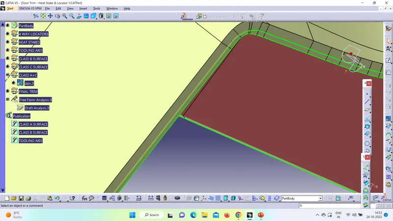
and we will get the complete closed surface as shown below:
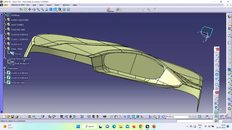
As we have enable the surface boundaries option. Due to non-present of green color lines , it states that our object is completely O.K.
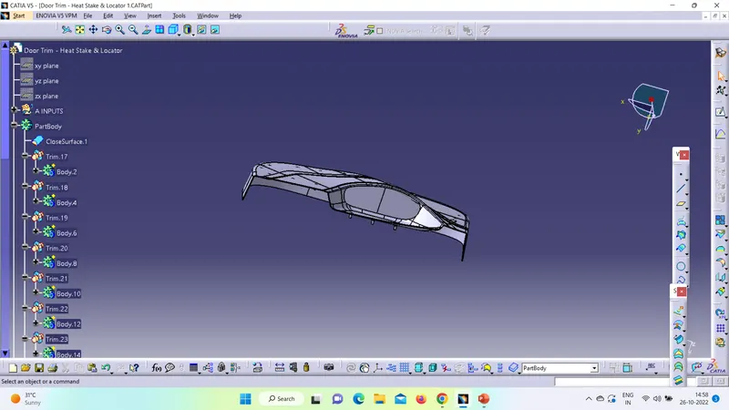
7. Closed Body - Now, go to part workbench and use the closed body option which will make our component completely closed.
Note - It will not apply incase of there is open boundary.
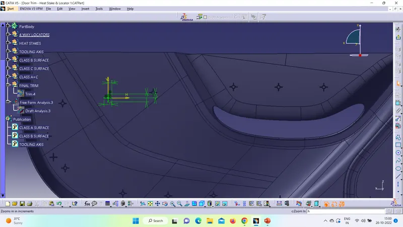
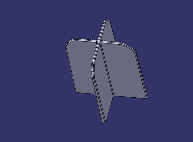
8. Create 4 way Locators - To create the locators, I created a sketch on the body. After creating the sketch, I pad it 20mm in height and thicken it to 1.3mm and I drafted it with 0.5deg in the direction of the tooling axis. I gave 3mm of chamfer with 45deg of inclination and after I gave a fillet of 0.3mm radius.
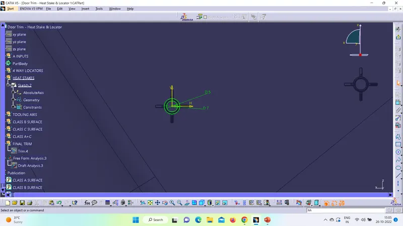
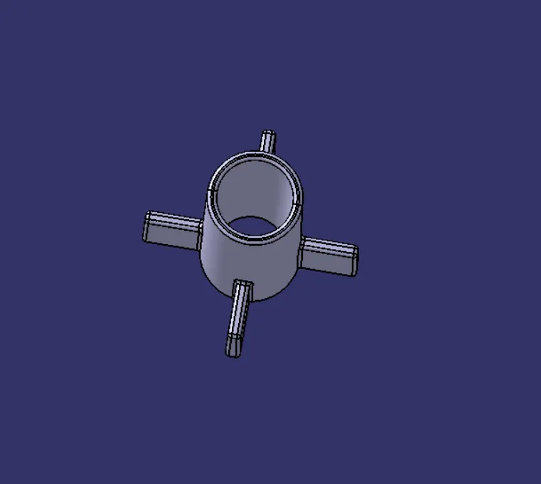
9. Heat Stakes - To create the heat stakes, I draw a sketch on the surface. After the creation of the sketch, I pad it to 15mm height and I gave a draft angle of 0.5deg on both sides (inside and outside) and then I gave a fillet with a 0.25mm radius.
Finally, we union trim the ribs with a heat stake to remove the ribs, which are present inside the heat stakes.
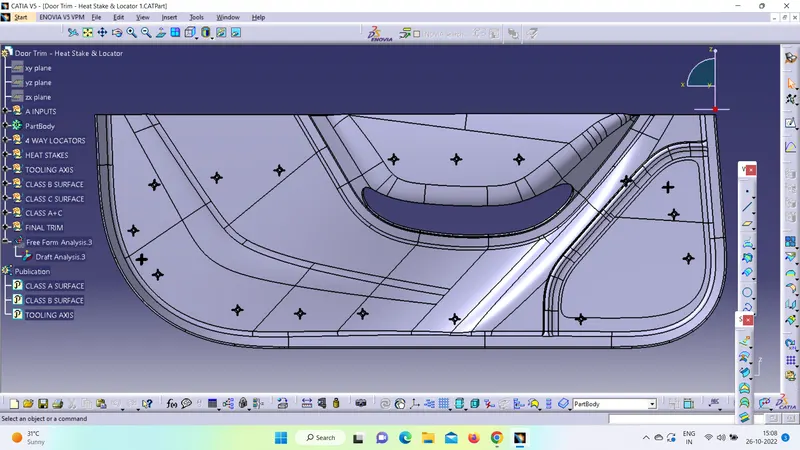
Now we will translated the heat stakes by copy-pasting them in the part body according to the requirement.
Final part body with 4-way locators including all the heat stakes with supporting ribs:
10. Draft Analysis On Final Component - Now, we will perforn the draft analysis og the final component as shown below :
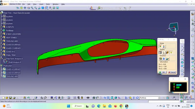
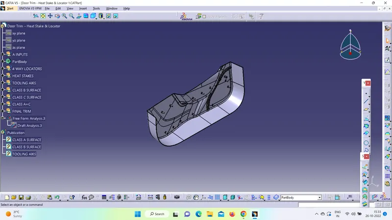
Different Views -
Isometric View:
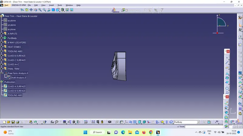
Front View:
Right View:
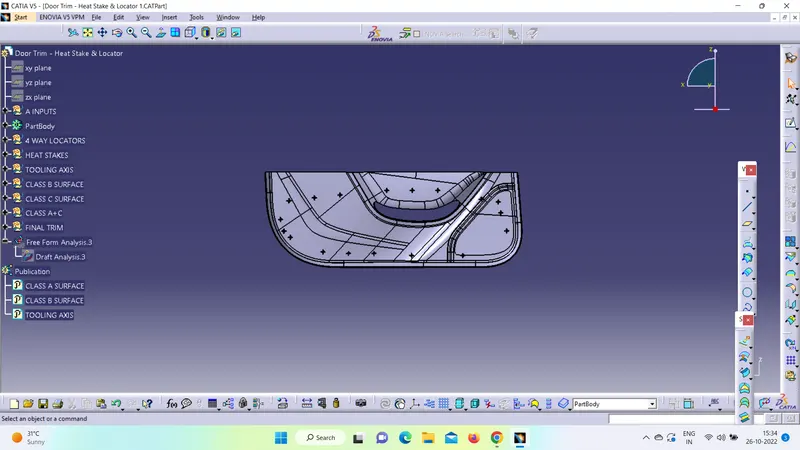
Top View:
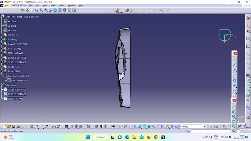
Left View:
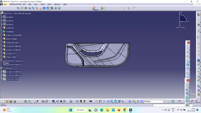
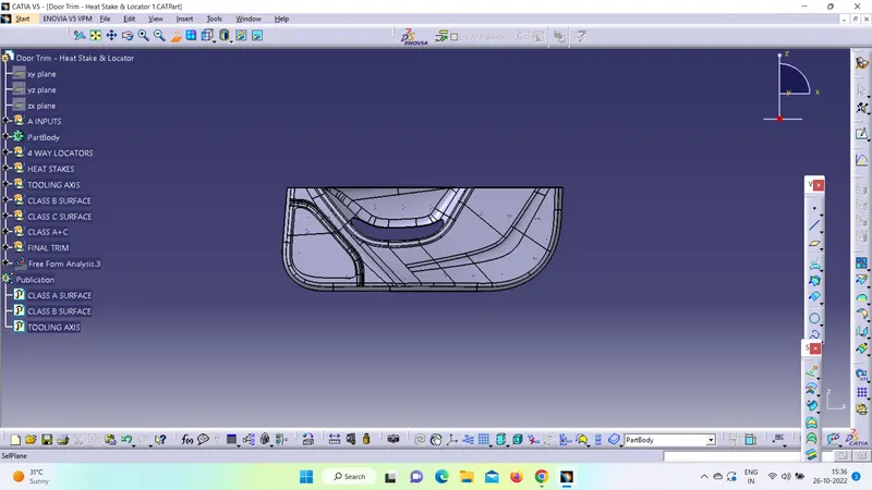
Feature Tree-
Conclusion - We have created the door trim lower plastic component through the given Class A Surface.