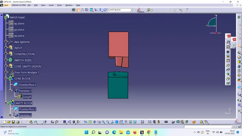
Week 8 - Challenge 6 - Core & Cavity Design
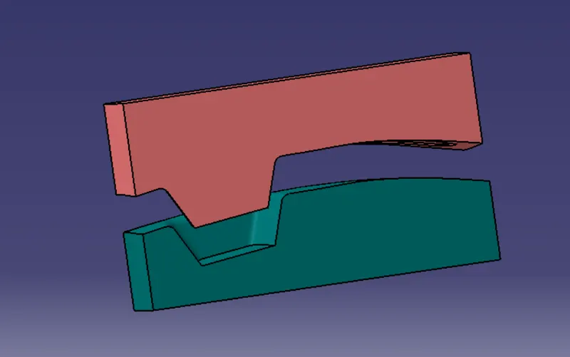
AIM : To create the core and cavity for the Switch Bezel Design.
INTRODUCTION : This report demonstrates the design of Core and Cavity Bloacks for an Automotive Plastic Component – Door Switch Bezel using industry principles such as Parting Surface and Parting Line definition, Draft angles, Draft Analysis, Determining and implementing of Tooling Axis, Class A, Class B, Class C surfaces and maintaining the Thickness of the part at 2.5mm. The Molds are designed using Surface Design and Solid Design techniques in CAD package CATIA V5.
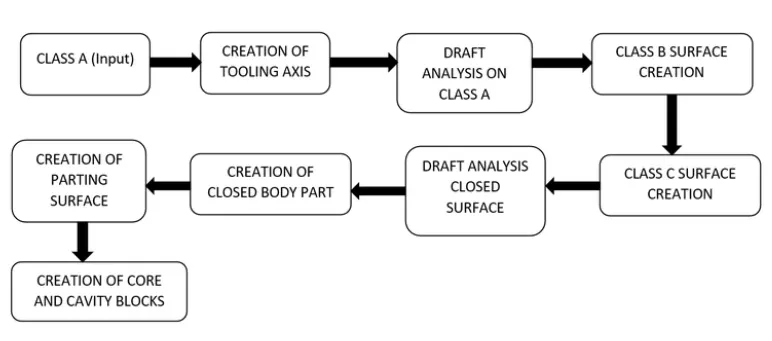
PROCEDURE : To create the above output, we need to follow the procedure which is explained below:
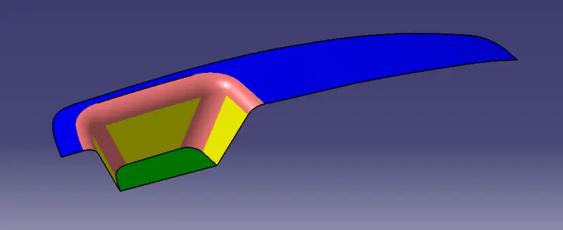
Step 1. CLASS A SURFACE - We need to have a design check on Class A Surface which can be done by following steps:
- After receiving the Class-A for the Switch Bezel check for the connectivity of the surfaces on it.
- Use Join operation, boundary operation and disassemble.
- The check is over if any discontinuities do not arise.
- Delete the operations after the check.
Step 2. TOOLING AXIS - We need to create the tooling axis by following steps:
- Identify faces which can potentially create problems while manufacturing.
- Surfaces at angles along a desired Tooling Axis.
- Extract a plain surface and create a point on its center for Axis system creation.
- In this case Z axis can be a possible Tooling Axis Direction.
- Create a sketch on YZ Plane creating Intersects for the 2 Faces.
- Create a Bisecting Line for the 2 intersects and it will be the Tool Clearing Axis for Y.
- Do the similar Sketch process in XZ plane.
- In this case there is only 1 wall for intersection with XZ Plane.
- For such cases, Sketch a Line at an angle greater than acceptable draft angle from the axis center origin on the same XZ plane.
- The angle chosen here is 7º.
- This Line itself is the Tool Clearing Axis for X, rename it with the same.
- Create a Bisecting Line for both Clearing Axis and name it as Tooling Axis.
- Publish the Tooling Axis as well as the Class A for easy access using Insert à Publication.
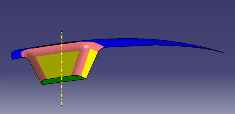
STEP 3. DRAFT ANALYSIS - Following adavantages of Draft Analysis are:
- Draft is an angular tapering given at the design stage to every Plastic Component that has to be manufactured.
- It is given in the direction of the Mold Movement.
- The Draft allows the parts to release easily from the mold without creating friction between the surface of component and the core and cavity plates.
- When a Plastic component cools down inside the mold, the natural tendency of it is to shrink and attach to the core or cavity half.
- The movement of mold opening causes friction on the walls of the component as well as the core/cavity blocks.
- This reduces the life of the mold as well as the component itself.
- The component may also have rough surface finish as well as weak structure due to this.
- This problem can be solved by giving draft to the component.
- Most applications require minimum draft angles of around 0.5º to 1º , however 3º draft angles are widely accepted for cost saving purpose.
- 7º Draft angles are given to textured surfaces like Instrument Panels.
- Minimum possible draft angles are given to screw bosses, ribs and stiffeners due to their critical nature.
Steps for creating Draft Analysis on Class A Surface:
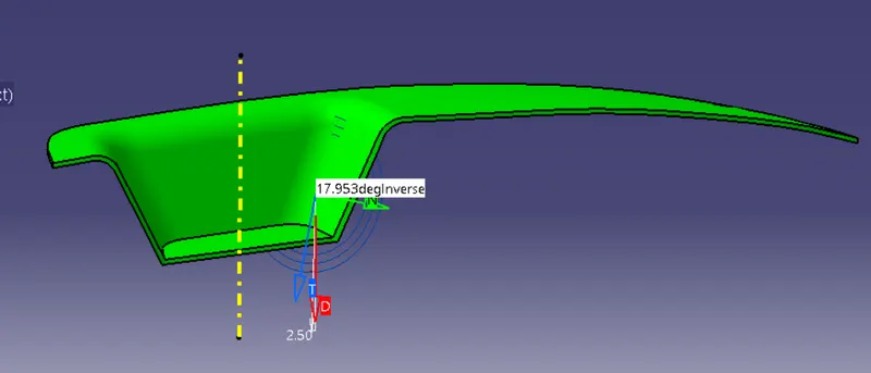
- Change View Mode Customization to Material mode
- Go to INSERT ---> ANALYSIS ---> FEATURE DRAFT ANALYSIS and move the compass to the Tooling Axis.
- Change the range to 3º.
- As shown the target area has 4.2º draft angle which was the concerned face.
- Thus, it passes the criteria of having suitable draft and the Class A can be further designed into a solid plastic component and manufactured.
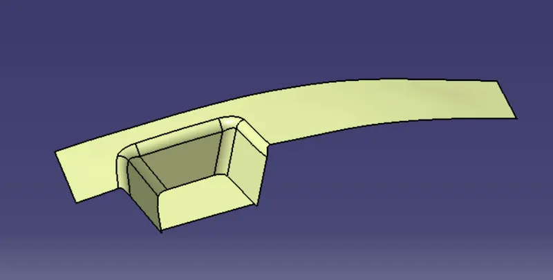
STEP 4. CLASS B SURFACE CREATION - Steps to be followed while creating Class B Surface:
- Extract the relevant surfaces from Class-A surface which excludes the Fillets and holes.
- Here the selected faces consist of Bezel Arm rest surface, Walls and the Base surface.
- Use Untrim Command to untrim the extracted surfaces and create a natural extend.
- Extrapolate the untrimmed surfaces so that each of them intersects clearly and pass way forward than the Class A which will help in its trimming in further operations.
- Offset the extrapolated surfaces to the value of required Thickness of the Part.
- In this case of Switch Bezel, the thickness value is 2.5 mm.
- The offset faces are the part of B-Surface.
- Trim the extra surfaces to obtain similar extended surfaces as in Class A.
- Create Fillets while maintaining the part thickness between the Class A and Class B surfaces.
- The Value of Fillet is given by the equation (B surface fillet = A surface fillet ` Thickness of the Part).
- The sign + or – must be decided so as to maintain the part thickness which in this case is 2.5mm.
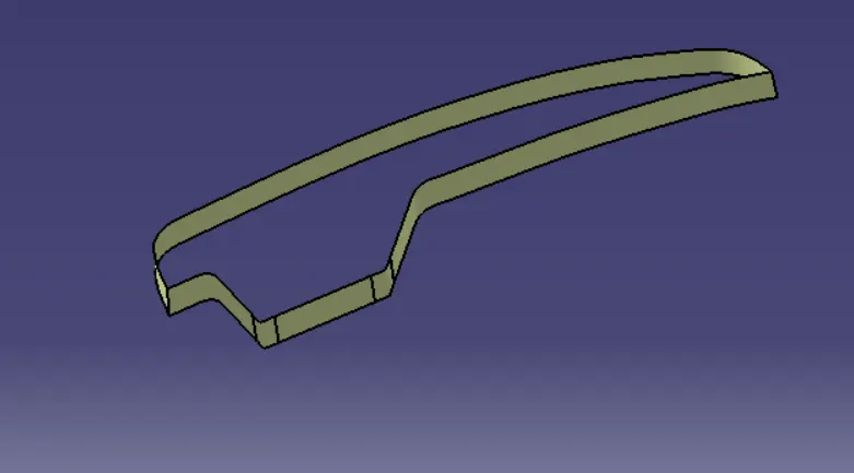
STEP 5. CLASS C SURFACE - Steps to be followed while creating Class C Surface:
- Use Multiple Extract to extract the outer boundary of the Switch Bezel Class A surface.
- Use Smooth Curve since the multiple extract creates multiple sections.
- Use Sweep Operation to extrude the boundary using the Draft direction option and selecting the Tooling Axis as the direction.
- Use draft angle as 3º and select outward direction arrow.
- Sweep it well beyond the B surface.
- Use similar Sweep for other Smooth curve and if any gaps are found extrapolate and trim to make an enclosed surface.
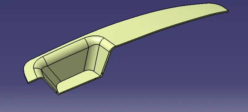
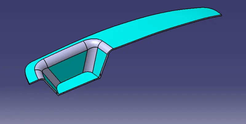
STEP 6. CLOSED SURFACE CREATION - Join all the Swept surfaces along with the Class A Surface. In this case gaps occur while joining so use 0.003mm. Even this method doesn’t fill up the gap so extrapolate Class A to about only 0.5mm and trim it off with C surface. The Final trim should be one single Surface Entity without any gaps. Trim the Final Trim Surface with the Class B surface to obtain the final enclosed Surface for the Switch Bezel.
Step 7. PARTING SURFACE - Generally, injection moulding has two major components - Movable Half and the Fixed Half.During Injection Molding process, these 2 halves are pressed together tightly to form a sealed hollow to avoid the melt flow leakage and maintain certain holding pressure. The pressed surface is called the Parting Surface.
Usually the parting surface are the biggest projection outline of the part.
Parting Surface directly affects the Product Quality, Ease of Construction and Operation of the Injection of the Mold, the Mold Design is one of the key factors to the success.
Design of Parting Surface should follow the following Design Principles:
- Designing the Mold Structures should be as simple as possible.
- Avoid or reduce side parting as much as possible to reduce complexity of mold making.
- Ease of De-Molding. The plastic component must stay at the fixed half in most cases and ejected by the Ejection System and avoid side De-molding action.
- Ensure Dimensional Acccuracy of the molded parts and try to make parts with similar dimensional accuracy requirements in the same module to reduce manufacturing and assembly errors.
- Ensure Appearance Requirement of the molded parts.
- Flash or mismatch usually occurs on the Parting Surface, so it shoul not be designed on a High quiality requirement Surface.
- Ensure adequate Venting or De-Gassing. If possible Parting Surface should be placed at the end of the Mold Flow. This can be a good advantage for Filling and Venting.
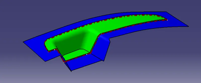
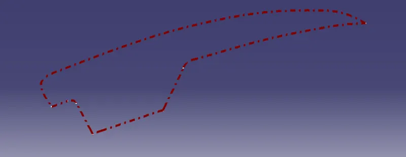
Step 2. PARTING LINE - Intersection of the Plastic Component with the Parting Surface is called the Parting Line. It is the Bordered Outline of the Component along the Parting Surface.
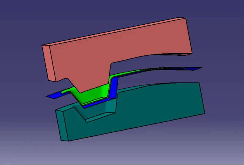
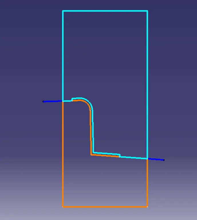
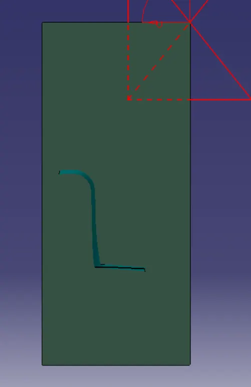
CONCLUSION : The final output is shown below:
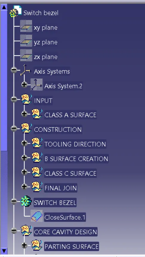
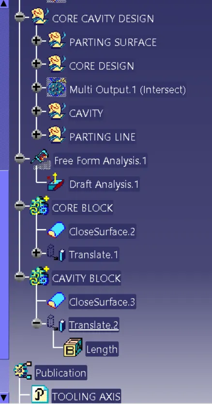
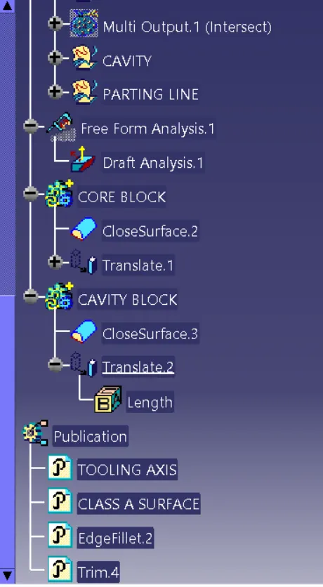
Feature Tree :
Isometric View :
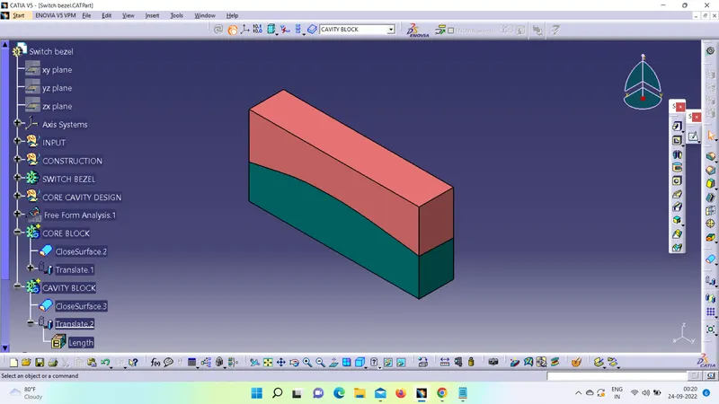
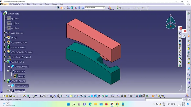
FRONT VIEW :
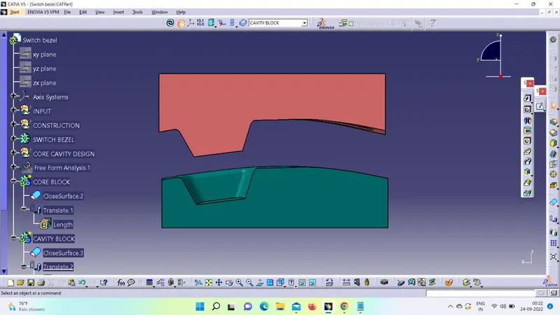
TOP VIEW :
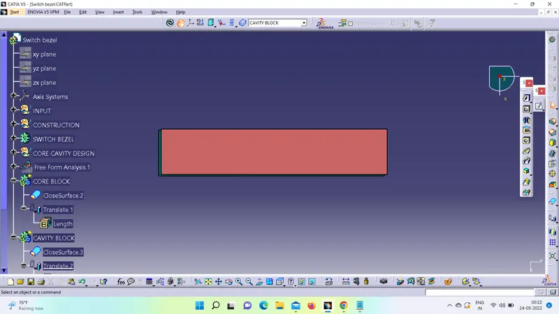
SIDE VIEW :