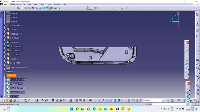
Week 9 - Attachment Feature Creation - Challenge 2
AIM - To create the Dog House for the Door trim considering the design rules.
Introduction -
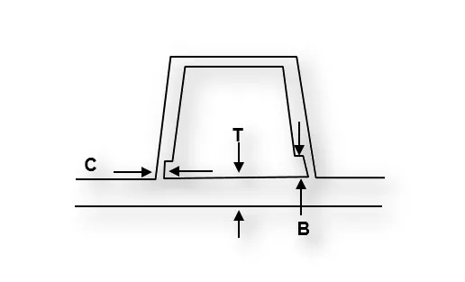
Dog House - Dog house is an engineering feature used in plastic trim design. Dog houses are used as supporting feature. Sometimes other engineering features like snaps, locators, ribs, screww bosses etc. are mounded on them to increase their strength.
Dog houses are subjected to draft analysis to prevent breakage of the component during ejection from the mould cavity. Dog house and oher engineering components are built on the B-surface.
Design Methodology -
Class A surface - We need to check the class A-Surface which was designed by styling team by boundary or join to check there is no error or gap in that surface.
Class A-Surface is given below:
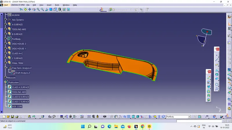
Create the Tooling Axis -
- Need to check best possible the direction by manually adjusting the compass in all three directions.
- After analysis, it is found that Y axis is the best direction, because every feature is only visible in that one.
- Now, we will create the tooling axis by using Bisecting method.
- First we will create a intersection of CLASS A SURFACE with respect to YZ plane which is shown below.
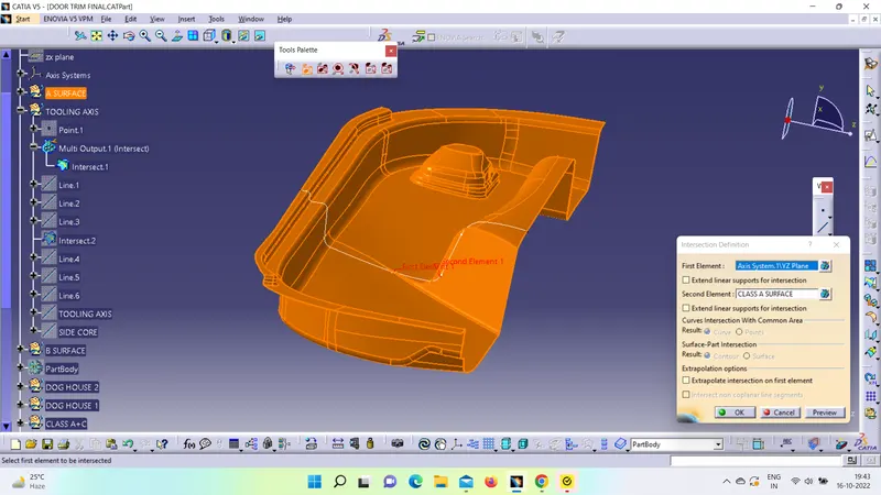
- Now, we will create two line using point-point tool in the both sides as shown below.
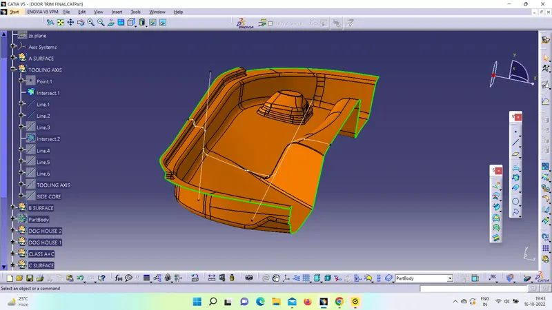
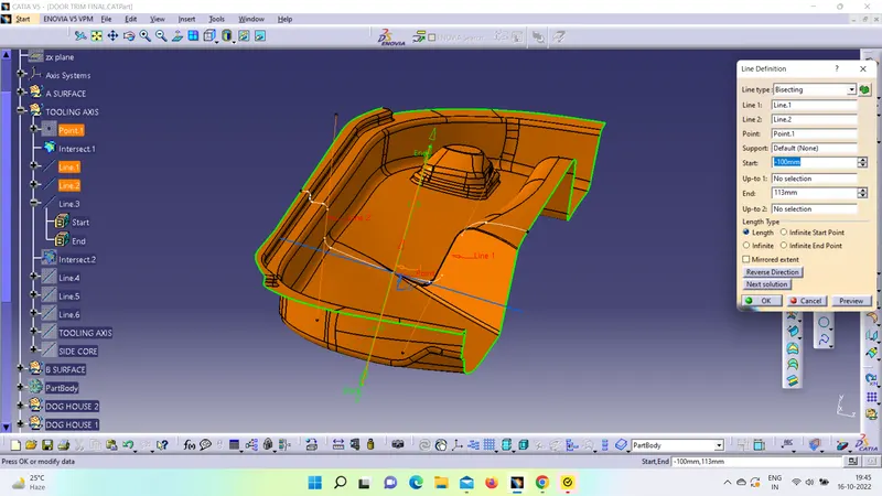
- Create a bisecting line using line 1 & 2 as shown below.
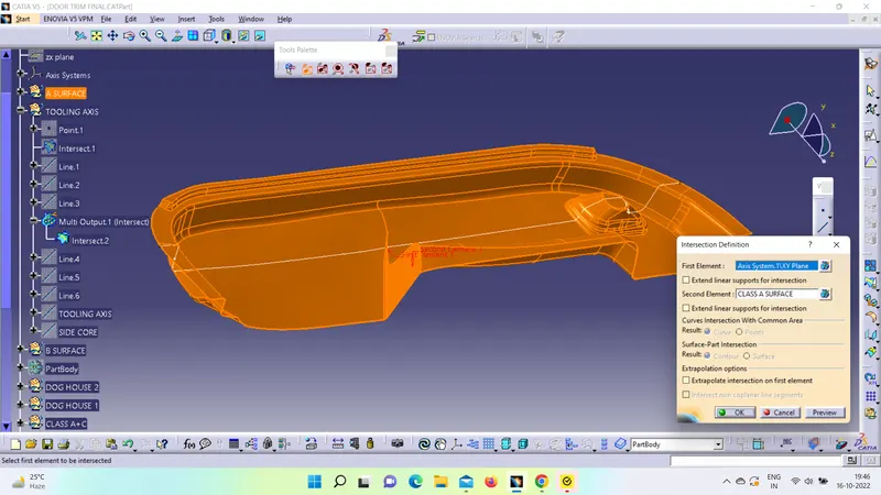
- Create another intersection using XZ plane and Class A surface as shown below.
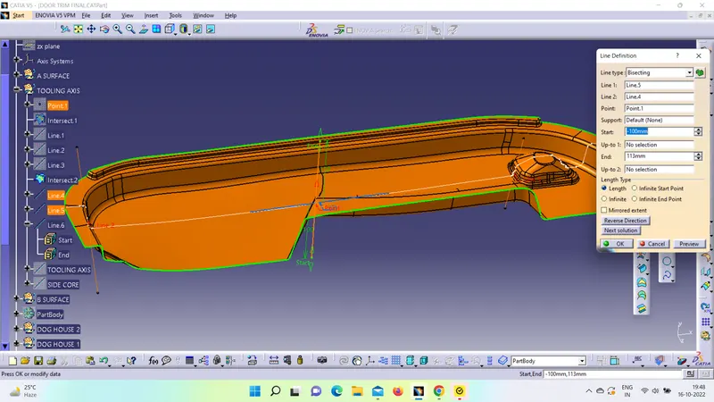
- Now, all above steps will followed again to create another bi-secting line as shown below:
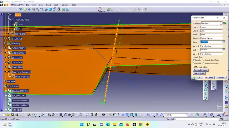
- Now we will create the tooling axis using the bisecting line 1&2 as shown below.
SIDE CORE AXIS - The core is usually the interior or noncosmetic side of the part. The core side also contains the ejection mechanism that pushes the completed part out of the mold.
We will create the side core axis by creating a line using the point which is normal to the Class A Surface in the Z direction.
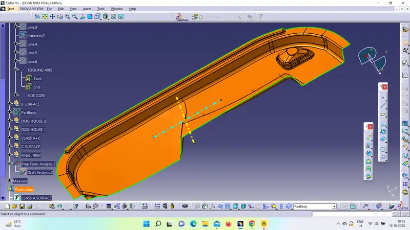
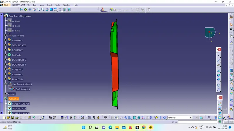
DRAFT ANALYSIS ON CLASS A - SURFACE - Now, we will perform the draft analysis on the Class A Surface as shown below:
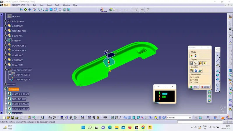
CLASS B SURFACE - Now, we will create an offset of 2.5mm in the downward direction from the Class A Surface.
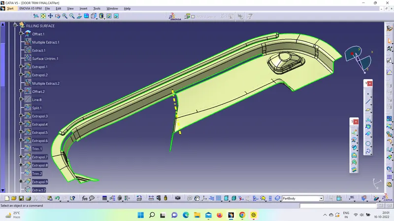
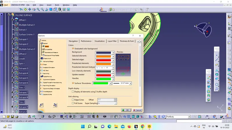
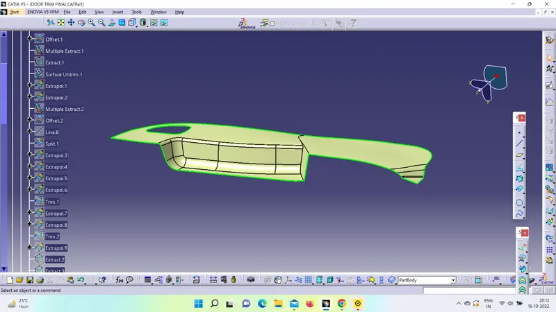
But it will show some patches or gap which is highlighted below:
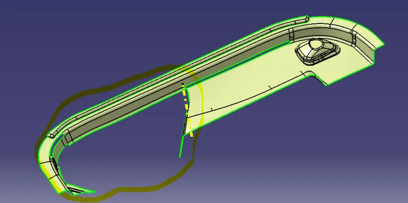
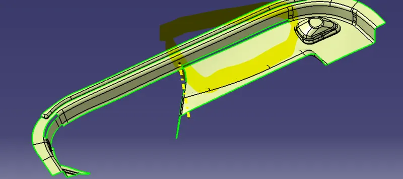
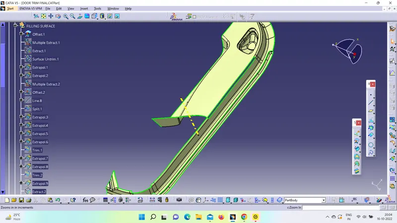
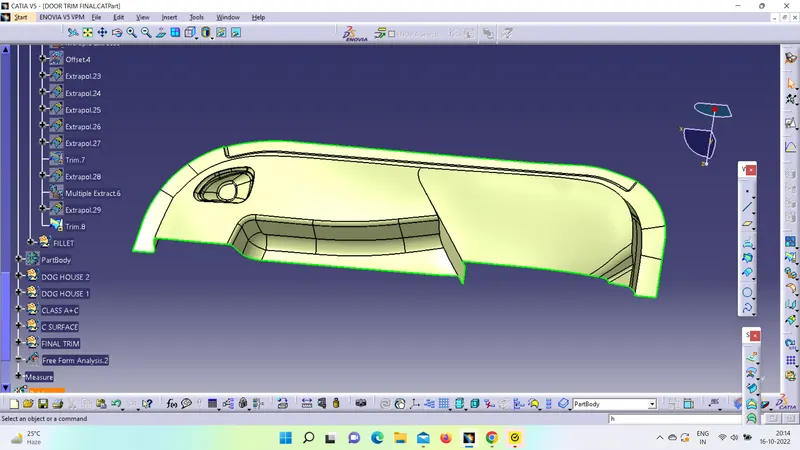
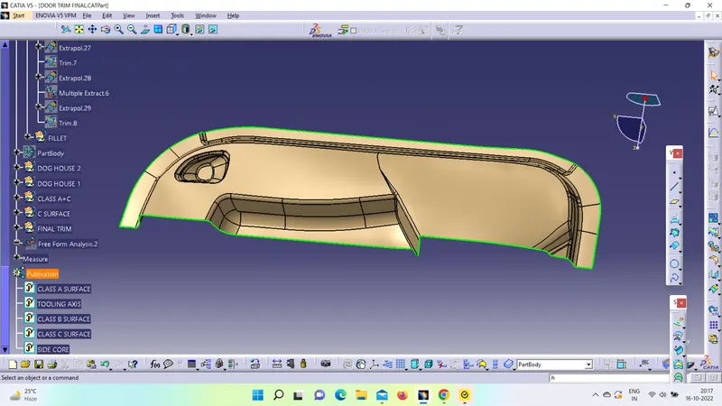
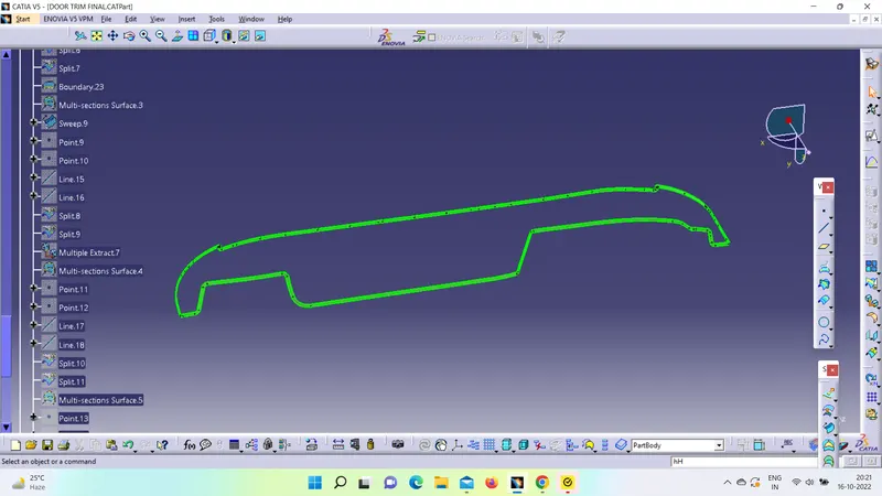
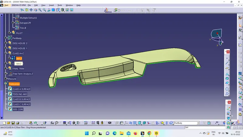
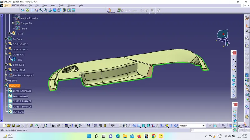
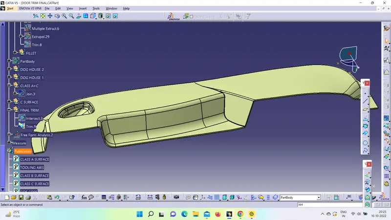
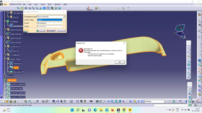
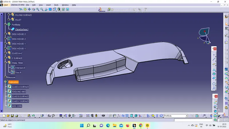
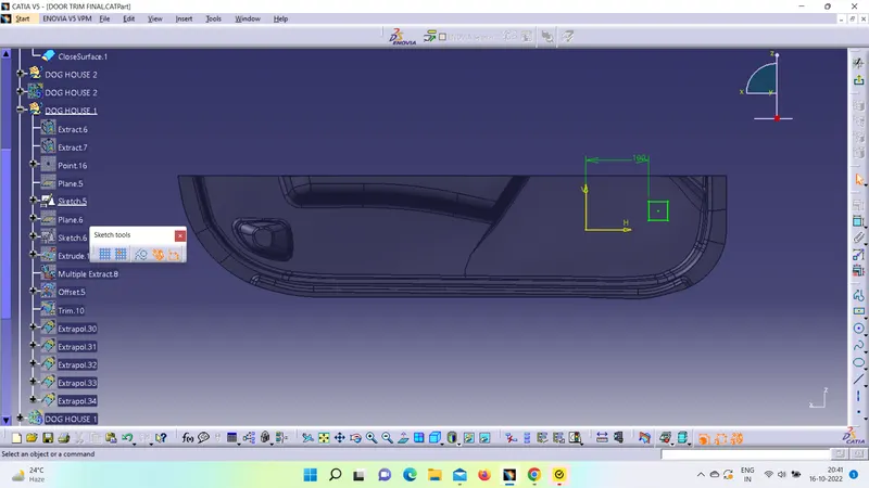
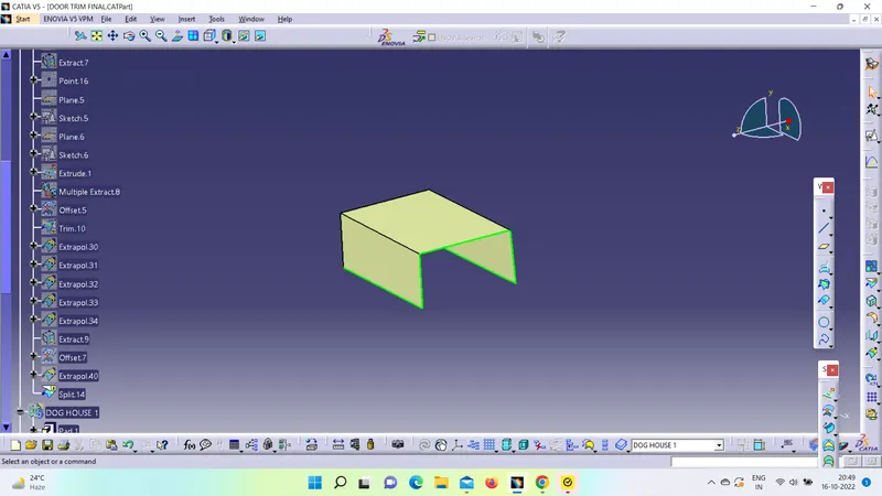
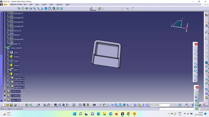
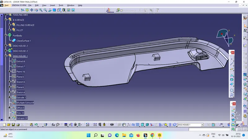
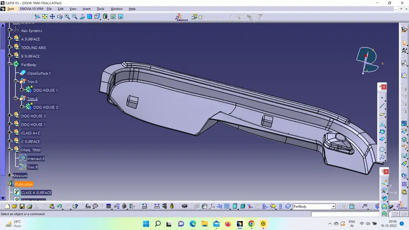
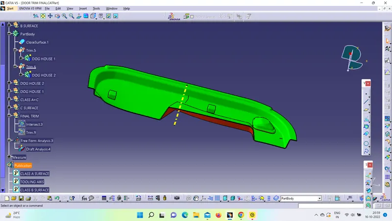
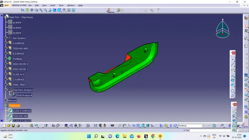
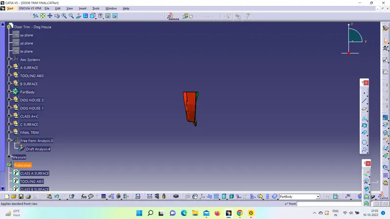
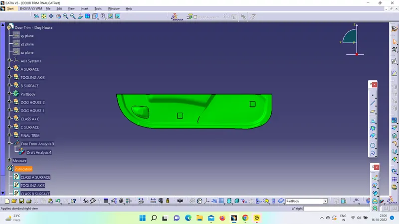
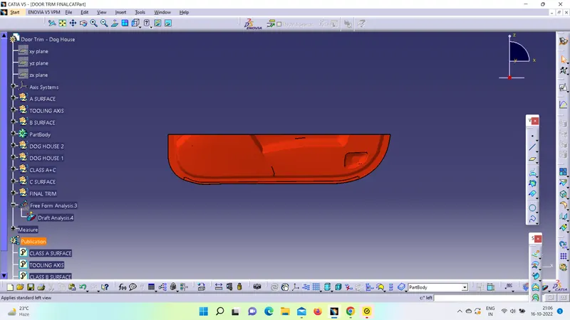
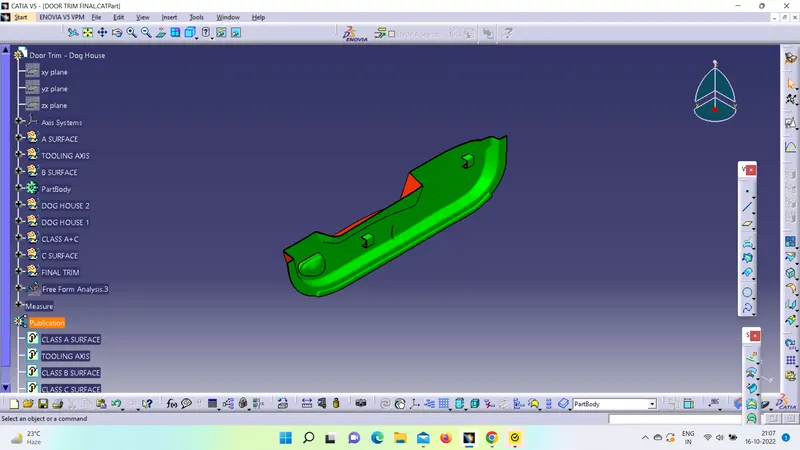
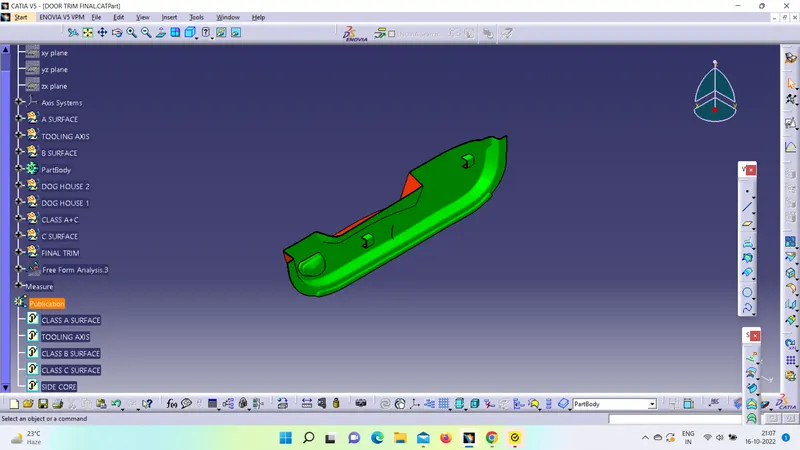
And even by enabling on the surface boundaries option in Tools Now, fill the gaps by in the first open boundary by using below tools: Same procedure will be followed for all the left open boundaries as sown below: Now, sue the fillet tool to dressup the above one by taking an Extract By using above methods, we will the complete B surface we required, as shown below: CLASS C SURFACE - Create the Class C Surface by Sweep, Line, Point, Multiple Extract, Multi Section Surface, Split, from the Class A Surface. We will get the surface which is shown below: CLASS A+C - Join the class A and C surface which is shown below. FINAL TRIM - Now, we will trim the Class (A+C) surface from the Class B Surface. We will get desired surface as shown below. To check that our surface is completely OK. Click on the Boundary tool. If it shows a popup then we can proceed further. CLOSED SURFACE - Now, create a closed surface as shown below: DOG HOUSE CREATION : Now, create the dog house on the given surface by using below standards: STEPS TO CREATE DOG HOUSE : Now, use the union trim to join the dog house with respect to door trim. It will remove all the extra surfaces of dog house. DRAFT ANALYSIS - Now, we will perform on draft analysis on the complete solid body as shown below: 3D part models in various orientations: Isometric View - Front View : Right View - Left View - Top View - Feature Tree - Conclusion - We have created the Class B & C surface and dog house using the given Class A Surface.