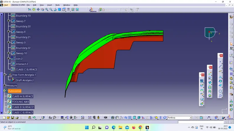
Week 8 - Challenge 4 - Bumper
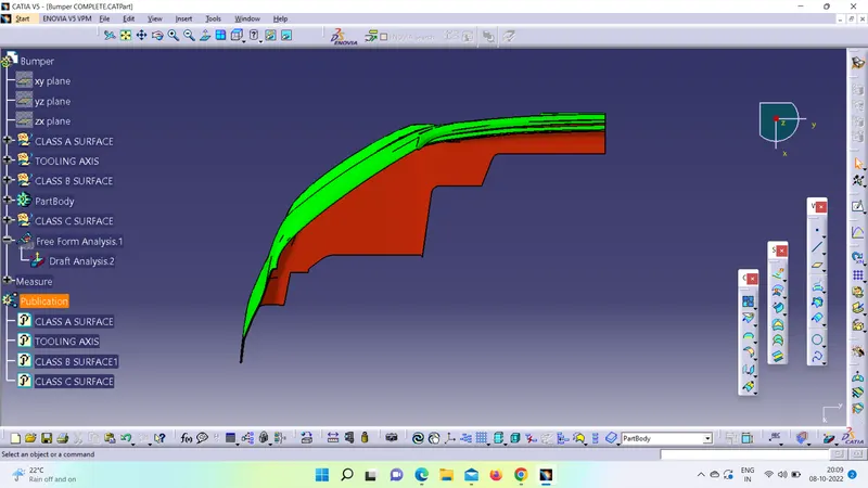
AIM - To create the Bumper Plastic component using the given class A - Surface meeting the requirements of the draft angle and at the end perform the Draft analysis on the model.
The thickness of component is 3mm.
PROCUDURE :- We have to follow the below steps to design and perform the draft analysis on the model :
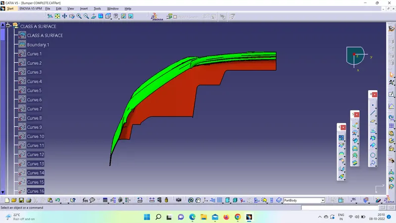
- CLASS A SURFACE - The class-A surface is used in the automotive design industry. It describes the final production surface data for the aesthetic parts.
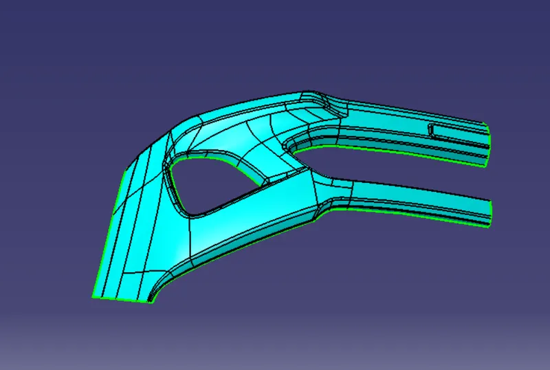
2. TOOLING AXIS - To create the tooling axis first we have to check the best suitable direction for tooling by using the compass. the x direction is suitable for creating the tolling axis because in the x direction most of the surfaces are clearing while performing draft analysis. Generally tooling axis is created using bisecting line method but here A line normal to the surface is created in the x direction and considered the tooling axis.
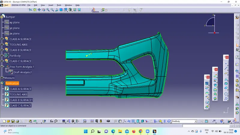
3) CLASS B SURFACE - We need to create the Class B Surface by taking the offset of 3 mm from the Class A Surface in the downward direction. While creating an offset, there is a popup appers which states to create an offset whithout the sub-elements.
After clicking on yes, we will get the surface with some patches which is shown below:
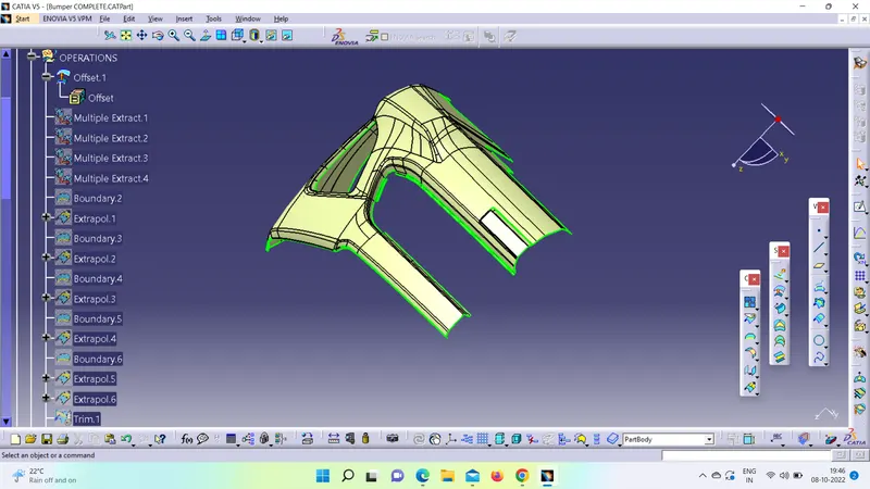
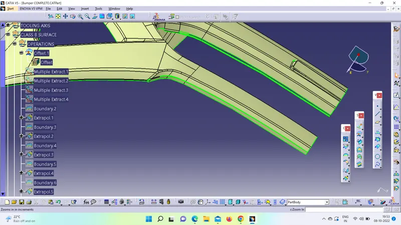
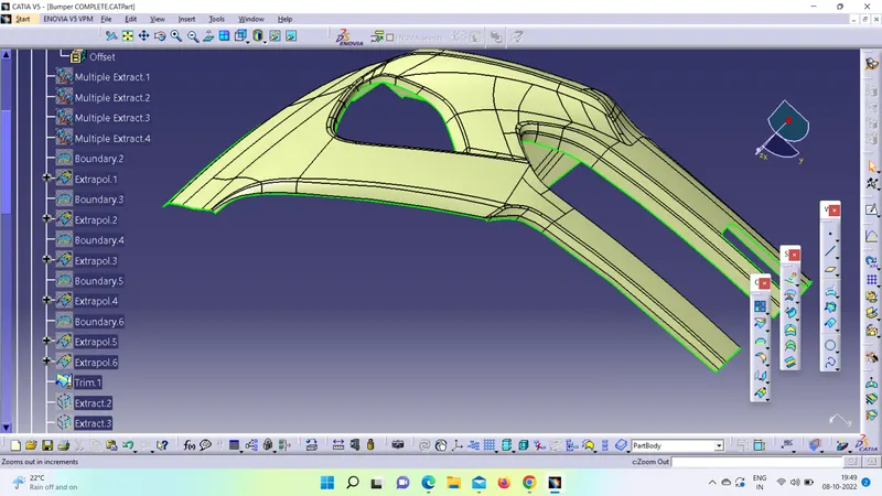
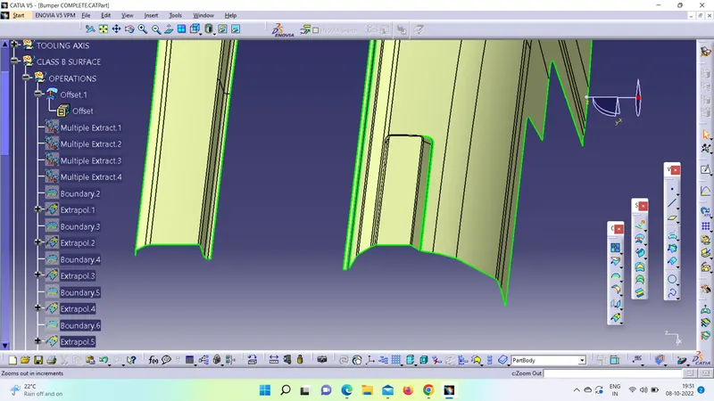
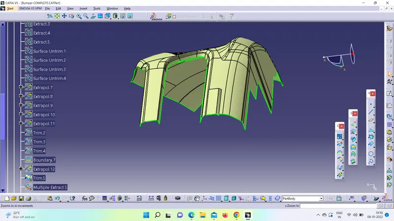
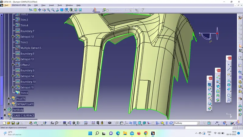
Now we need to eliminate the patches, by using Multiple extract , Boundary, Extrapolate, or Extract Extrapolate shown below:
(i) Incomplete Surface:
Complete Surface:
(ii) Incomplete Surface :
Complete Surface:
(iii) Incomplete Surface:
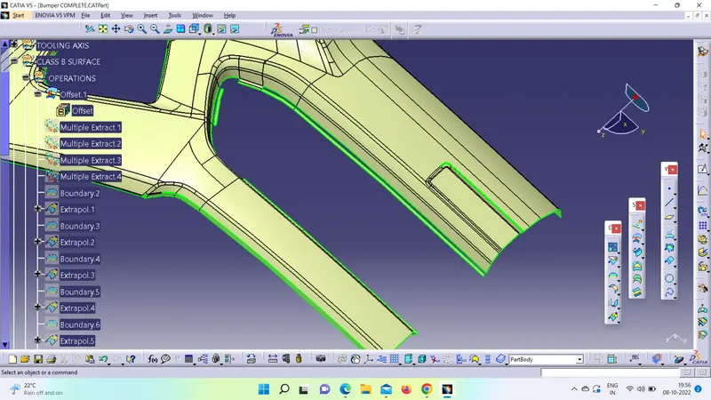
Complete Surface:
4) CLASS C SURFACE - We first extract the edges from the Class A surface with the help of the multi extract or boundary command which we create the path for a sweep for class C by creating separate sweeps and join them together. Once all the sweeps are created then join all of them with Class A Surface.
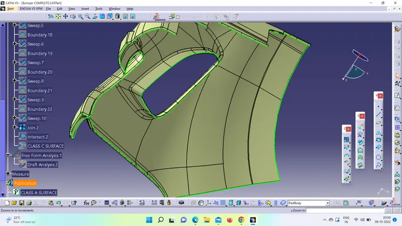
Then trim the class-B surface with join (A+C) this will make sure that we get a closed surface. We can check it using the boundary tool, if it gives an error that means that the component is closed.
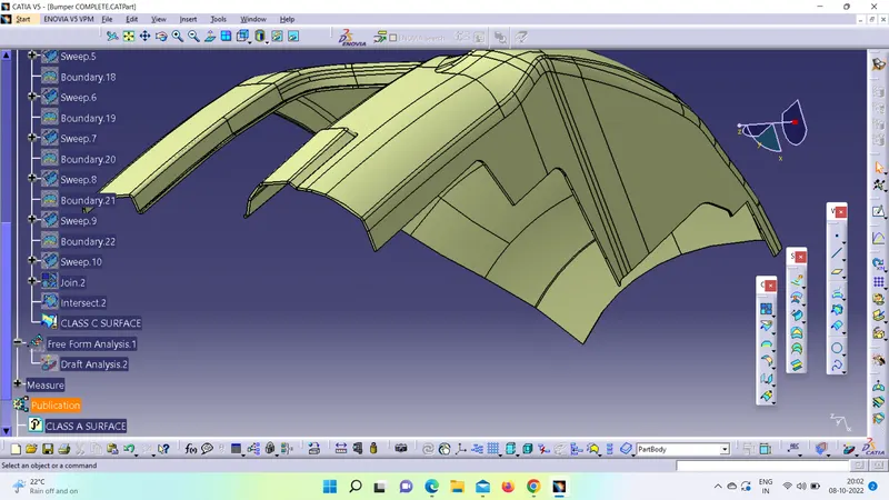
5) CLOSED SURFACE - After eliminating all incomplete surfaces, we will create the closed surface from the B Surface.
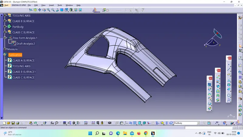
6) DRAFT ANALYSIS - We need to perform the draft analysis on the closed surface by following below steps
- Go to the Insert menu and select the Analysis option.
- Select Feature Draft Analysis.
- Select the Material option and select the surface.
- Drag the compass and place it on the tooling axis.
- Click on the surface and see that the surface is within the permissible limit of the draft values.
- Click on Okay.
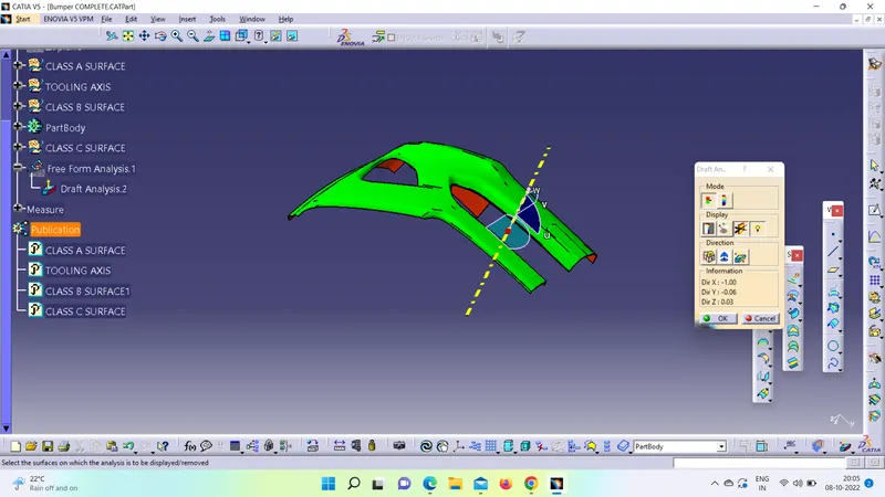
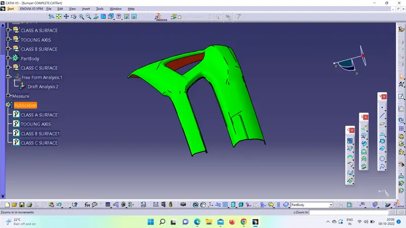
All views of the component:
Isometric View -
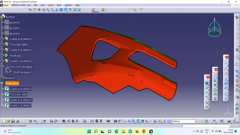
Front View -
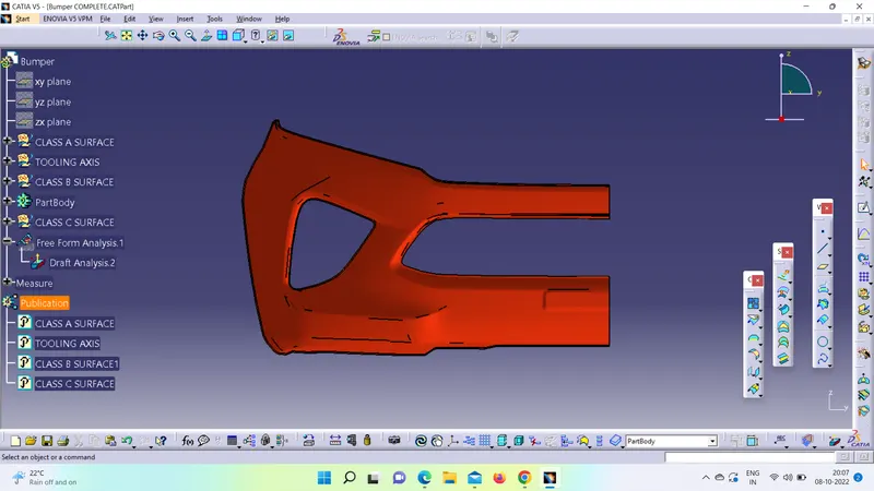
Side View -
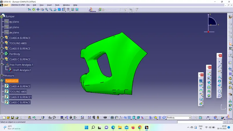
Top View -
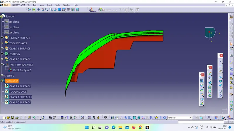
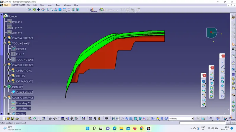
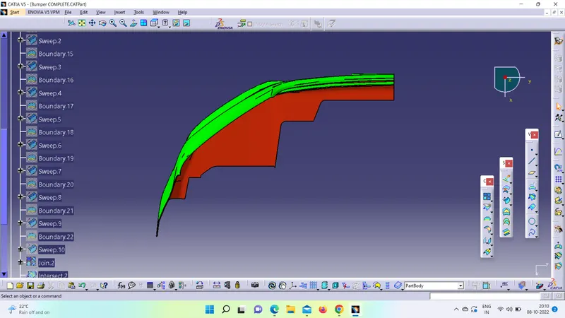
Feature Tree :