Week 8 - Challenge 1 - Base Bracket Design
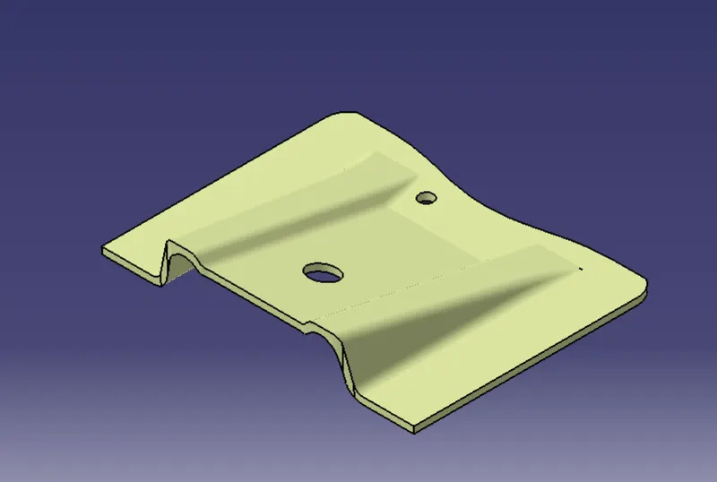
AIM - To create a Base Plastic Componenet from the below given Class A Surface:
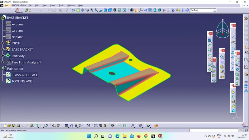
Class A -Surface - A surface made by the designer which is given as an input to the plastic modeler to work on. It is an aesthetic surface and the outer most surface.
In this assignment, we have done the follwing steps:
1) TOOLING AXIS - Firstly we need to ensure that the class-A surface is properly joined and has no discontinuity on it. For this we can use boundary command or join command.
a. Analyze the model manually or visually to see which direction is most suitable for tooling axis.
b. As in 3D view we can see 2 holes and a flat surface, we can directly take the tooling axis perpendicular to that. But to be sure,let us analaze from all the views. The below images of the front side and top views shows the areas that we have to keep in mind while choosing tooling axis. As from X we cannot see one hole so we cannot take axis along this. In Y we cannot see any holes so here too we cannot take tooling axis. But in Z we can see 2 holes and flat surface so we can take tooling axis.
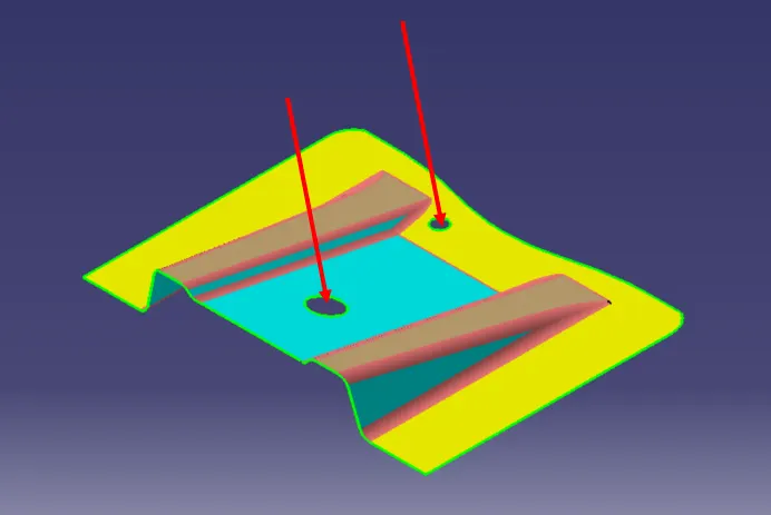
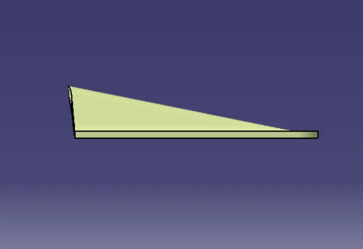
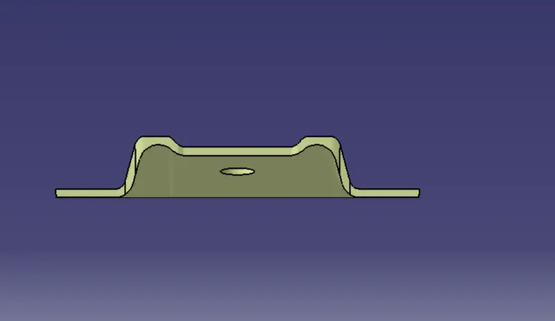
In Y-axis surface looks like -
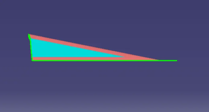
In X-axis surface looks like -
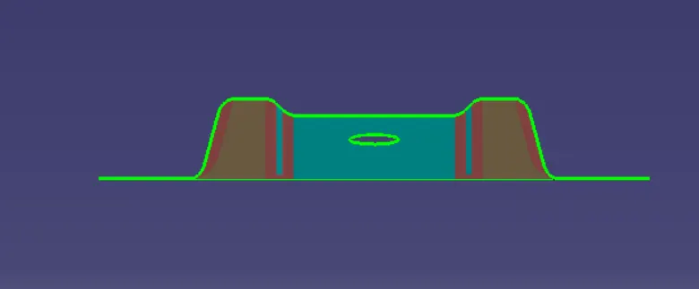
In Z-axis Suface looks like :
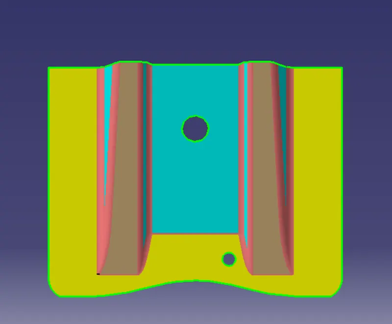
All holes are clearly identified only in Z axis. So, we will create the intersection in Z-axis only.
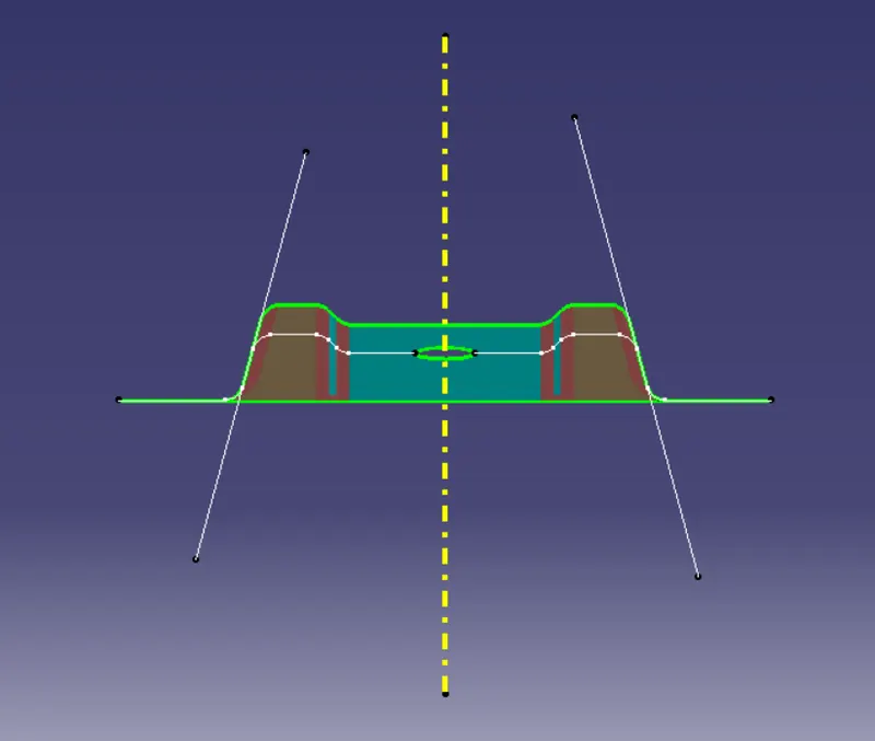
Intersection In ZY-axis- Intersect ZY plane and we are unsure of these two surfaces, so we make a line and bisect them both and this will be our tooling axis which, not so surprisingly, is the same as our guessed tooling axis.
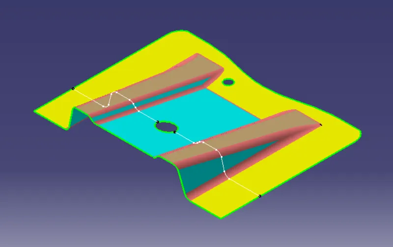
Now, we will create the tooling axis using the ZY plane by using bisection line as shown below by following steps-
- Click Line .
- Select the Bisecting line type.
- Select two lines.
- Select a point as the starting point for the line.
- Select the support surface onto which the bisecting line is to be projected, if needed.
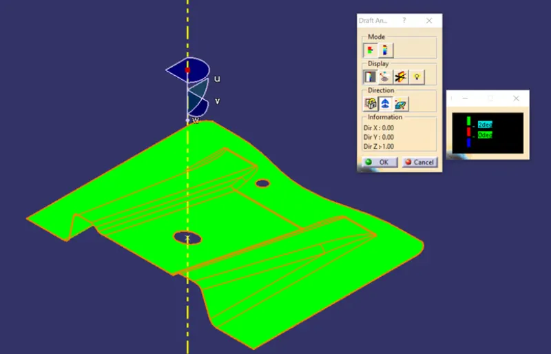
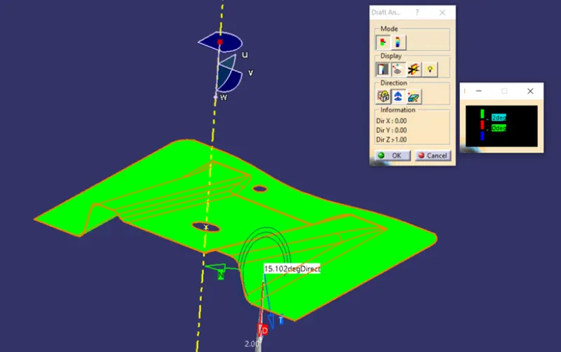
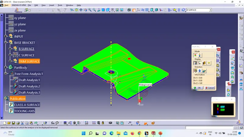
2) DRAFT ANALYSIS - Follow the procedure-
- Go to insert< analysis< feature draft analysis.
- Align the tooling axis with the compass.
- Click on the surface and see that the surface is within the permissible limit of the draft values.
- The surface should be green and in the column proper value (3deg) should be inserted.
3) CLASS B SURFACE - We will work on the surfaces individually. First of all we will extract the two ribs which are shown below:
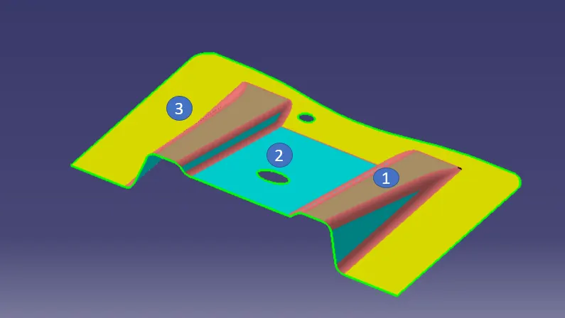
1) First of all we will create 2 Ribs from the class A surface by following steps:
- Extract all the three flat surfaces one by one.
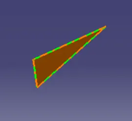
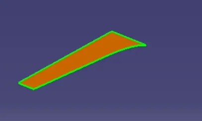
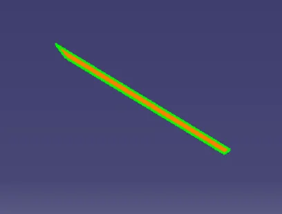
- Untrim the surfaces.
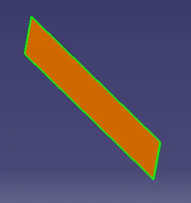
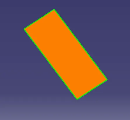
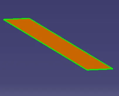
- Extrapolate all of them.
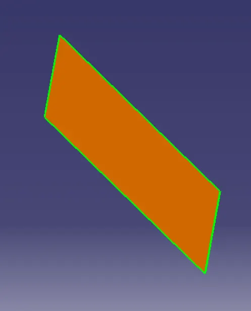
- Trim to get the desired shape.
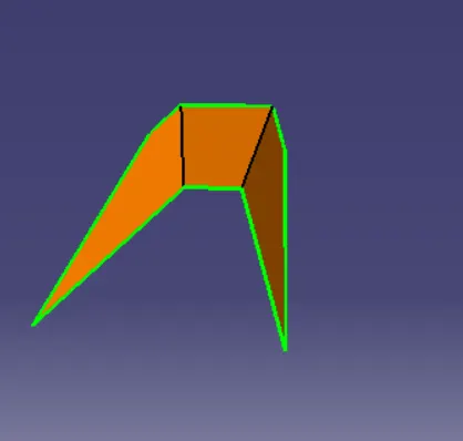
- Offset it by 2.5mm i.e. thickness.
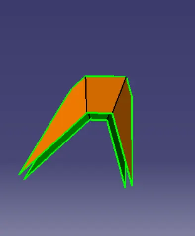
Repeat the same procedures for other rib also.
2) Now, we will follow the same procedure for base surface to get the below output.
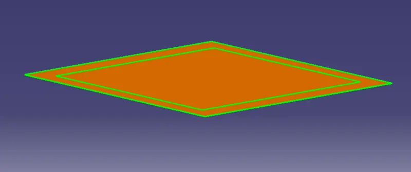
Once we have finished doing this, we have to trim the surface to get exact shape of the class-A surface (without fillet) below 2.5mm.
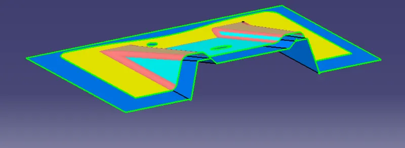
After the trimming part is done, fillet the model. Formula for filleting= fillet value+thickness (if the surface is below). We get our class-B surface.
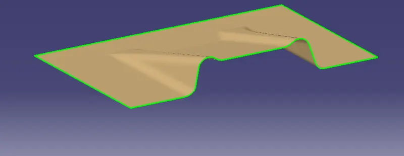
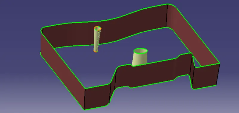
4) CLASS C SURFACE - Foolow the steps:
- Extract the boundary of the class-A surface.
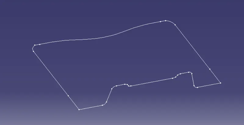
- Extract the boundary of the holes on the class-A surface.
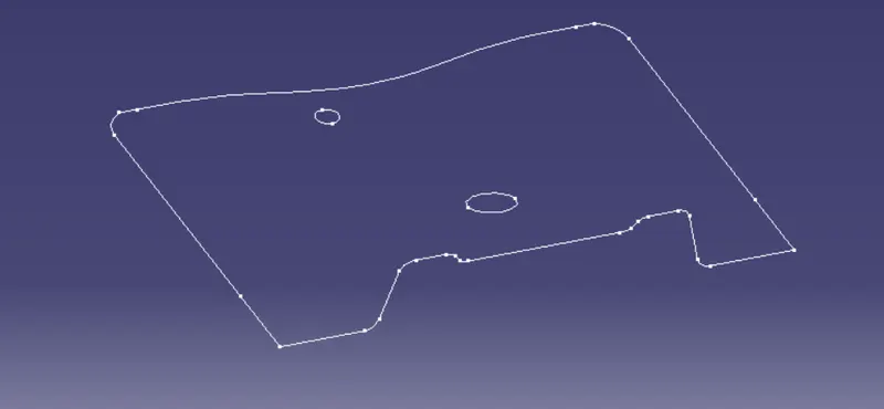
- Use sweep command on the boundaries one by one to get the class-C surface.
FINAL COMPONENT :
1) Join the class-A and class-C surfaces together.
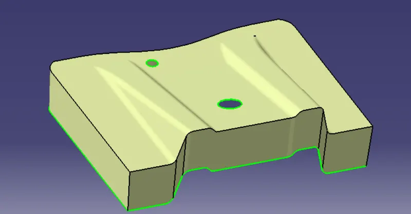
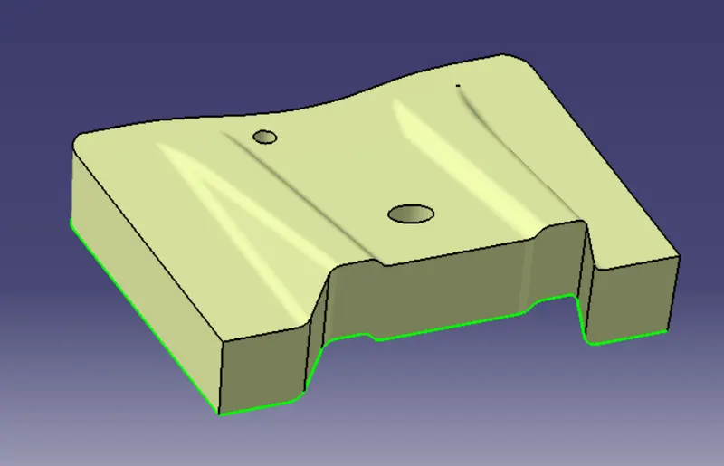
2) Trim the class-B surface with the join created earlier.
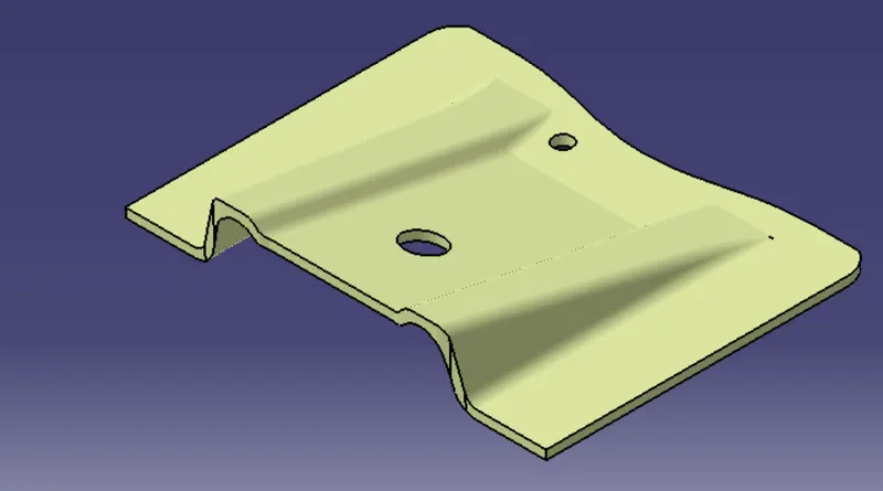
3) Go to part design and make a close model.
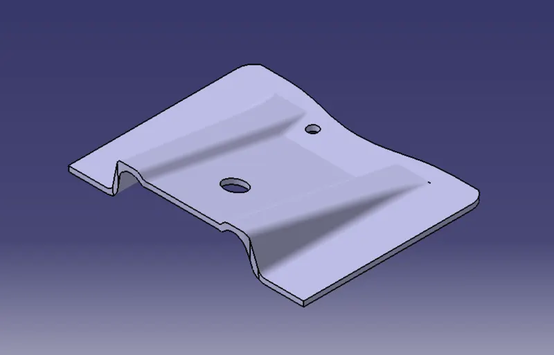
Isometric View of Base Plastic Component:
Right Side View :
Top View :
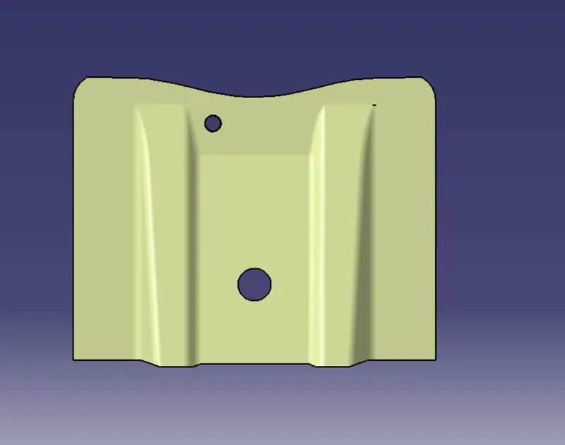
Front View :
Draft Analysis View after Class Join Class A surface, Sweep and Trim:
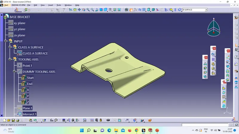
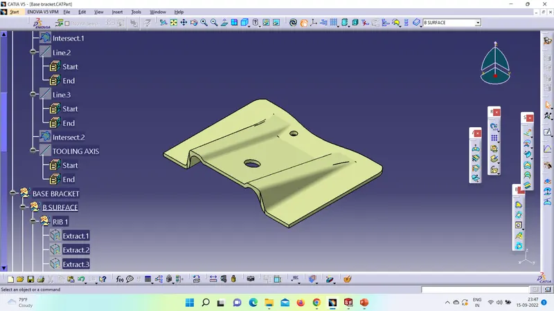
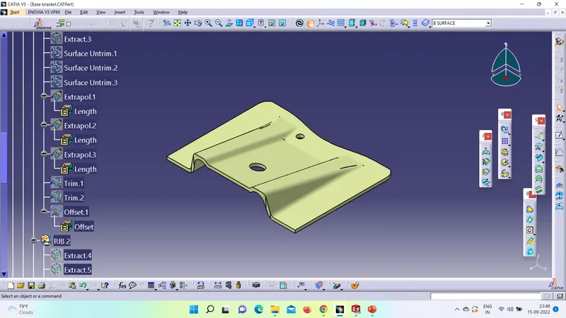
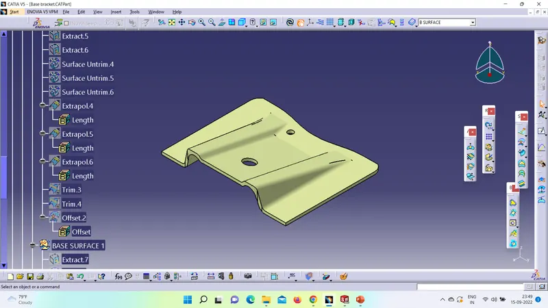
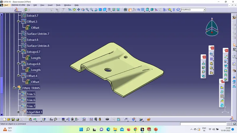
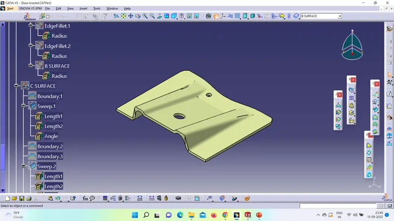
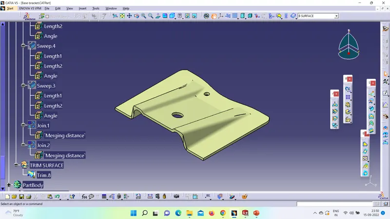
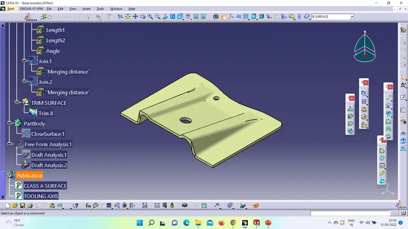
FEATURE TREE :
- Arunendra VishwakarmaGreat work ,