Photo Realistic Rendering
Design, Assembly and Rendering of an American Chopper Motorcycle using SolidWorks
Objective:
- To learn or understand the solidworks user interface, understanding and implementing shell feature sketch blocks and linear patterns in Solidworks.
- To understand the utility of Projected curve and Revolved cut feature in Solidworks.
- To understand gaining insights on Composite curves and make pierce features in Solidworks.
- To assemble the American Chopper
Introduction:
American Chopper is a two-wheeler and with the help of Solidworks software we design it. With the help of different modules in Solidworks which are used to design different components –
- Computer Aided Design (CAD) software like solidworks is very simple to use for the creation of 3D solid model and can be created faster. The main advantage is that everyone can use it as compared to other software.
- It is mainly used in many industries for the design and assembly of their product due to which productivity increases.
In solidworks, we use different modules for different purposes. Some of them are listed below: -
- Sketch Module – We used commands like Rectangular, Line, Arc, Circle, Spline, Filet, Chamfer, Point, Trim, Convert entities, Offset Entities, Mirror Entities and Pattern Command, etc.
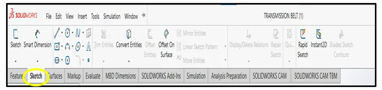
- Feature Module – We used commands like Extruded, Revolved, Swept, Lofted, Boundary, Extruded-Cut, Revolved-Cut, Swept-Cut, Lofted -Cut, Boundary-Cut, Hole, Fillet, Chamfer, Pattern, Dome, Rib, Draft, Shell, Mirror, Move, References Geometry, Curves, Split and Combine Command ,etc.

- Surface Module – We used Extruded Surface, Revolved Surface, Swept Surface, Lofted Surface, Boundary Surface, Filled Surface, Planar Surface, Offset Surface, Extend Surface, Trim Surface, Knit Surface, Freeform Surface, etc.

- Assembly Module – We used Insert Components, Mate, Linear, Pattern, Move Component command, etc. The different mates used in assembly are Coincident, Parallel, Perpendicular, Tangent, Concentric, Lock, Symmetric, Width, Distance, Lock, Angle Mate,etc.

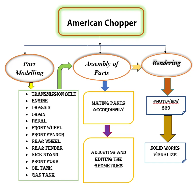
FLOW CHART FOR DESIGNING OF AMERICAN CHOPPER (USING SOLIDWORKS 2022)
Design Procedure:
STEP1: In this step, we have drawn each and every components of the chopper differently. The components which are drawn in American Chopper are explained below:
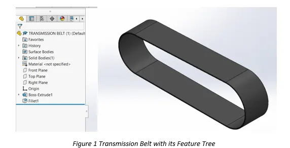
- Transmission Belt: It is made up of flexible rubber material. It transmits power from one shaft to another.
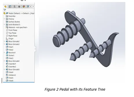
- Pedal: It is made up of strong materials, located in the lower portion of the chassis. It is used to provide the support to the vehicle while it is not in moving position.
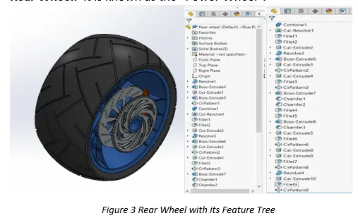
- Rear Wheel: It is known as the “Power Wheel”.
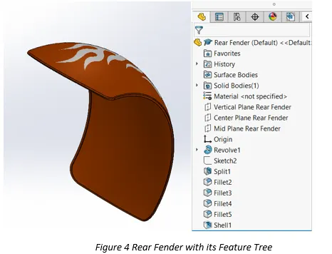
- Rear Fender: The rear fender is the frame installed over the wheel which protects it from water and mud spray.
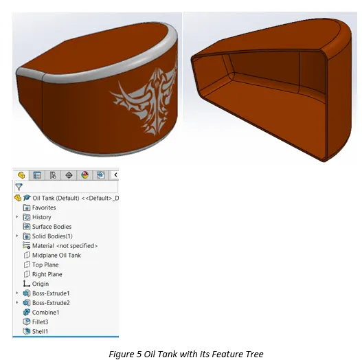
- Oil Tank: It is used to store to lubricant for the smooth running or functioning of the vehicle.
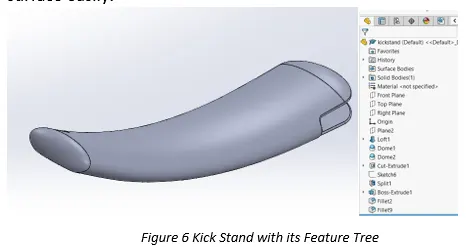
- Kick Stand: It is used in the vehicles so that the vehicle can stand to surface easily.
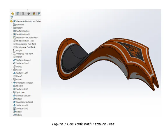
- Gas Tank: It acts as a reservoir tank.
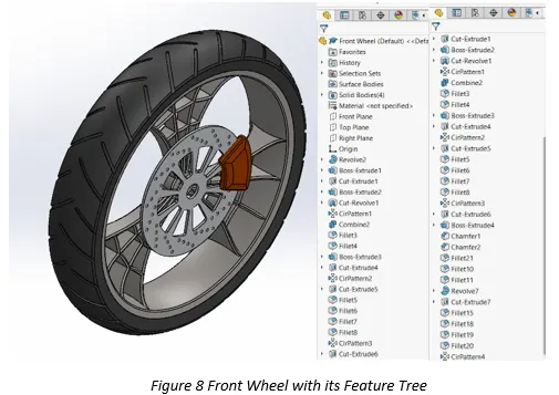
- Front Wheel: It can be defined as the guide wheel of the vehicle.
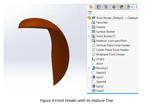
- Front Fender: The front fender also acts as same as the rear fender.
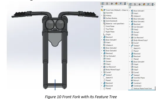
- Front Fork: It holds front-wheel which is used to provide the direction while riding.
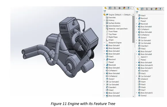
- Engine: Also known as the “Power-House” of the vehicle.
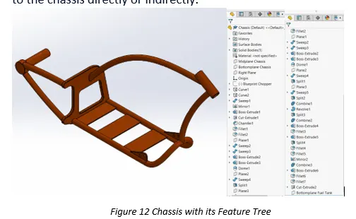
- Chassis: It is the structural unit that bears all the load of the vehicle body, ridder and the payload applied to it. Its purpose is to provide proper support and balance of the vehicle. All components connected to the chassis directly or indirectly.
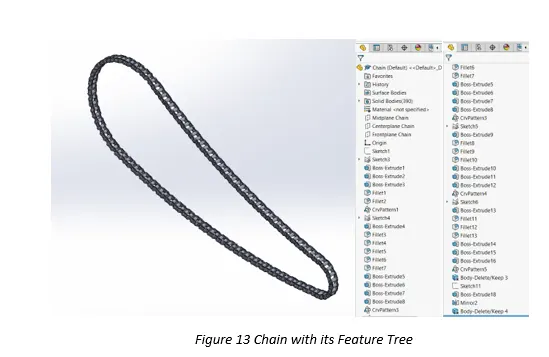
- Chain: It is way of transmitting mechanical power.
STEP2: Assembly- In this step we will take all components of chopper through Insert Command and fix them one by one with the help of mates command. This procedure is basically to join to every component and transform them into one individual body.
While doing the assembly we need to remember (+) sign indicates that parts are over defined and (-) sign indicates that parts are under-defined. Also , we need to ensure that each component is fixed with respect to line, vertex and planes, etc.
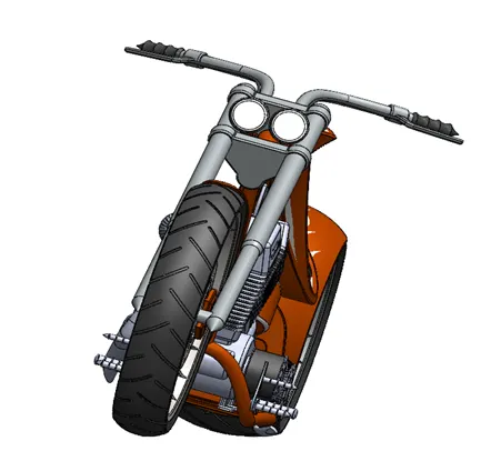
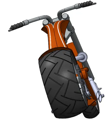
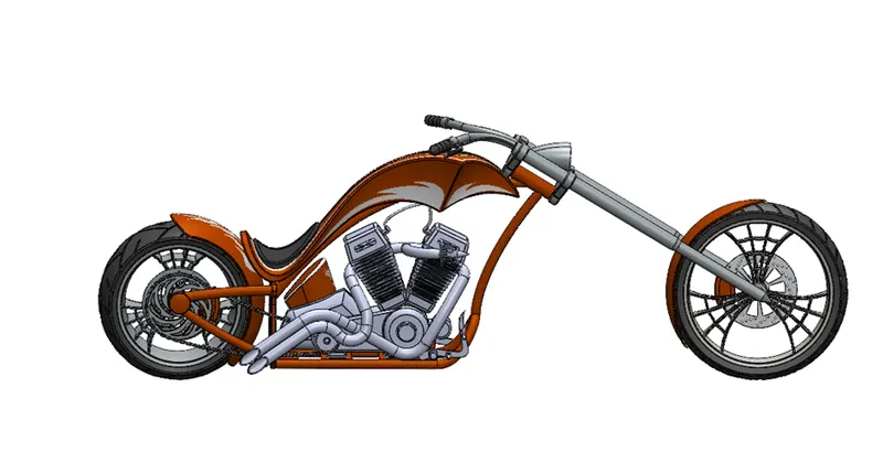
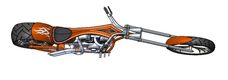
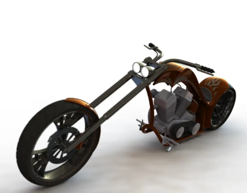
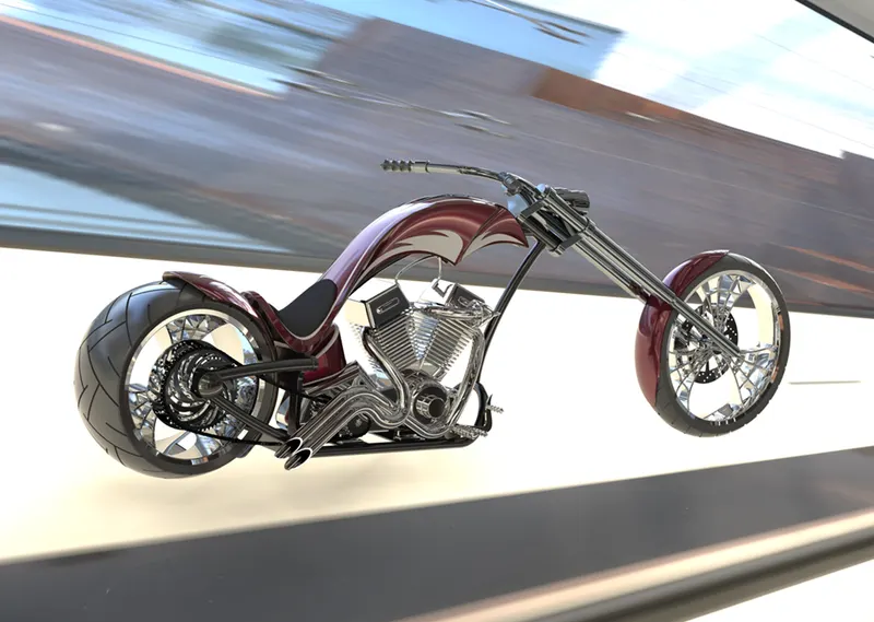
STEP3: Rendering- After assembling, for providing our drawing a realistic view we used Render tools. With the help of materials, appearances, colors, etc., our drawing will gain more attention than before.
Photo view 360: - Photo View 360 is a SOLIDWORKS add-in that produces photo-realistic renderings of SOLIDWORKS models. The rendered image incorporates the appearances, lighting, scene, and decals included with the model. We use commands like camera, decals, light, edit scene to make assembly more realistic.
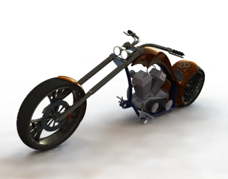
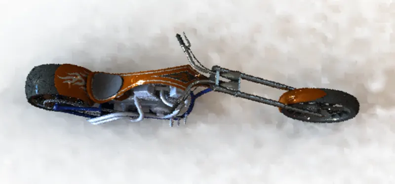
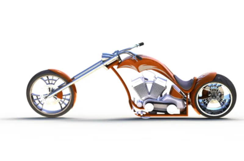
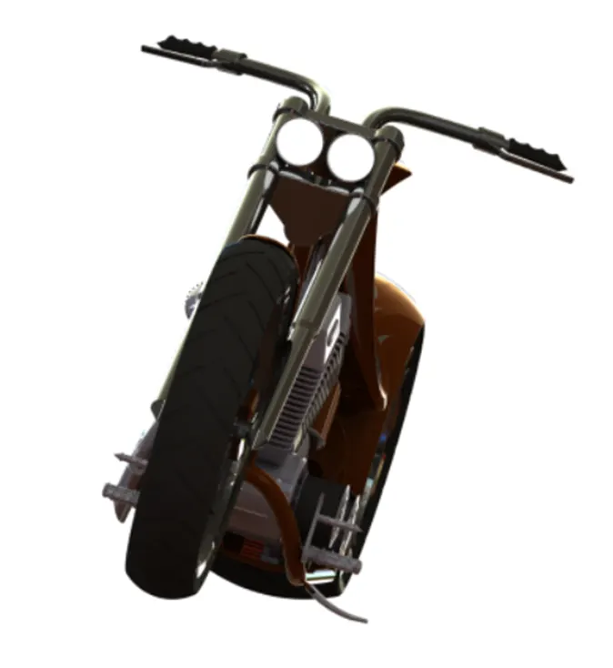
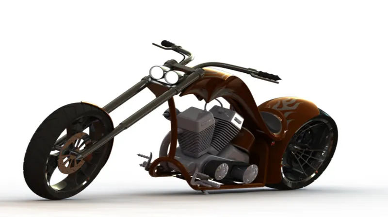
Solid works Visualize: - Visualize allows you to leverage your 3D CAD data to create photo-quality content in the fastest and easiest way you can–from images to animations, interactive web content, and immersive Virtual Reality.
Conclusion:
- A model has been developed with the help of Solidworks by using some global variables, dimension and equation.
- The users can update model just by changing ground clearance, Tire size, etc.
- In this way designer can perform tasks especially in the mechanical design.
- After this user are comfortable to design and modify different components.