Week 8 - Challenge 3 - Coin Holder Design
AIM - To create to the Coin Holder Plastic Component through the given Class A-Surface by creating Class B & C surface.
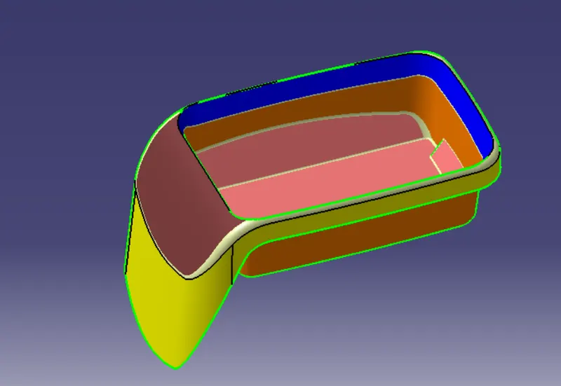
DESIGN METHODOLOGY - The procedure to follow for developing or design plastic product model by using class A surafce are explained below :
STEP 1 : Tooling Axis - The Tooling Direction is basically the direction that the mold pulls apart. The mold is built in two separate pieces - Cavity and Core side. The Core pulls apart from the Cavity and that's the Dyeline or the Tooling Direction.
First we have to analyse the model and find the suitable surface where the tooling axis can create.Then, extract the surface and by using normal to surface option in line creation tool and then create the tooling axis for the model.
Once the tooling axis is created we can do the draft analysis for the given class A surafce.
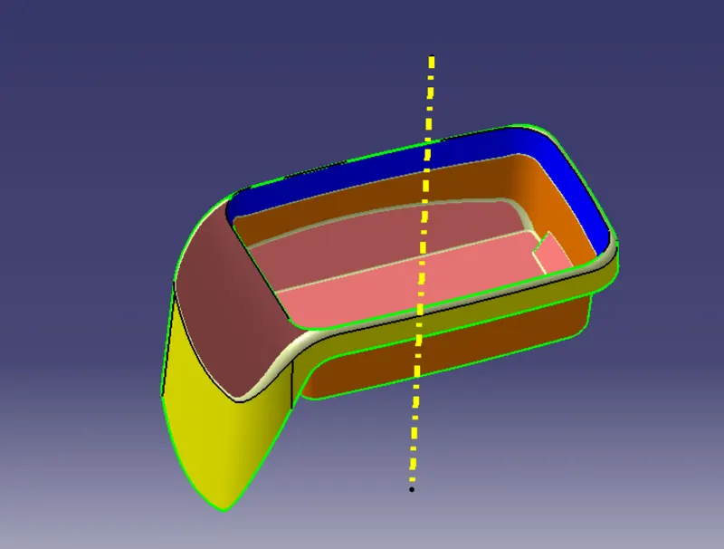
STEP 2 : Class B Surface - For this model, we need to create a number of surfaces by using extract or multiple extracts and then untrim them. After untrim, we need to create a extrapolate to intersect properly with the other part and then trim it. After achieving the desired component, we need to offset the component upto 2.5 mm in desired direction.
B Surface are divided into various parts which are mentioned below :
- Side Walls
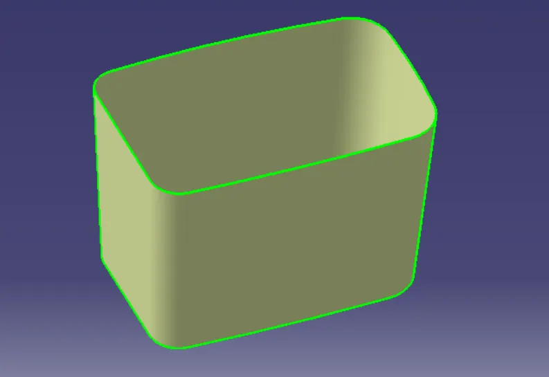
- Base
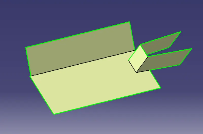
- Top Walls
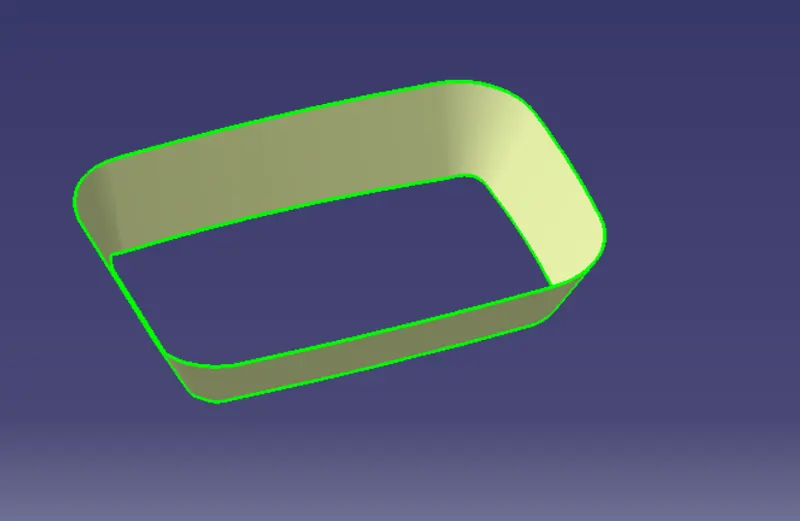
- Initial Trims
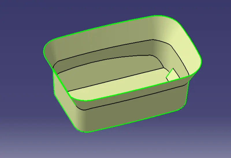
- Outer Flange
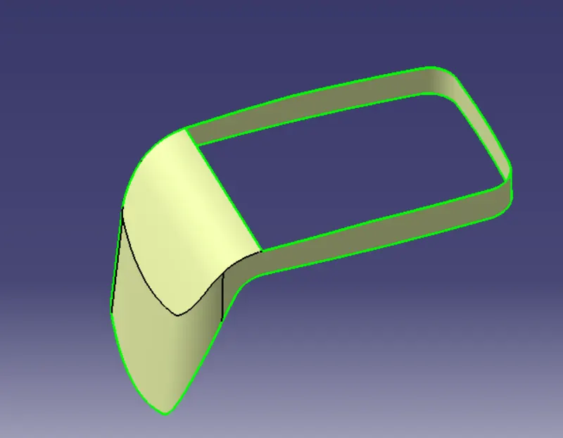
All these components will make the desired B surface we required for our design.
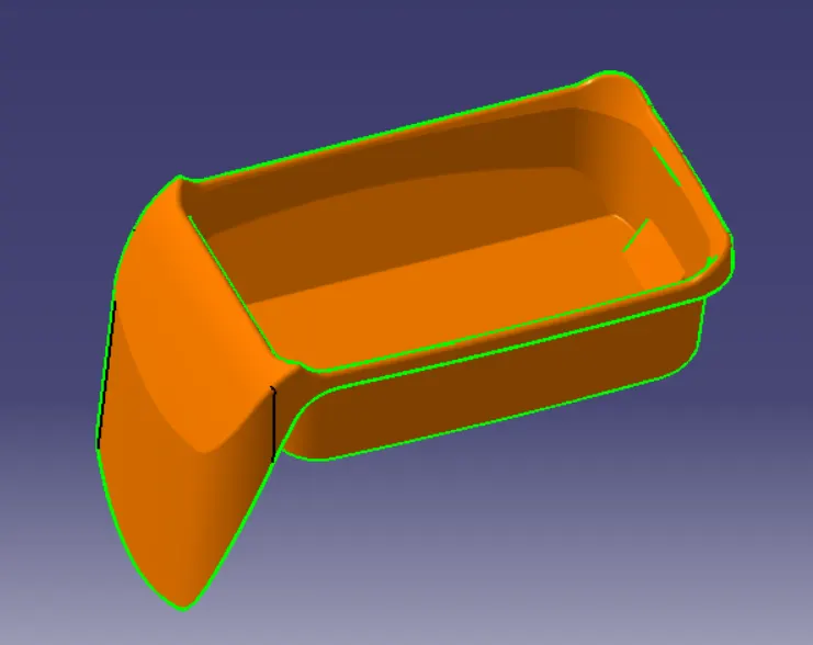
STEP 3: Class C Surface - The class C surface helps to connect the class A surface and B surface. The C surface is created with the reference of class A surface and tooling axis. When the class C surface is created we have to give the proper angle, if the draft angle is not given then it will create problem while moulding the product.
First we have to take the boundary for the class A surface edges and then we need support surface. Now, by using both surfaces we will create the Class C Surface as per our requirement
Once th C surface is created then need to check the proper intersection of C surface and B surface. By joining and trimming common we have to join the C surface with the class A surface and after join need to trimmed the C surface from B surface, so at the ned we will get final close surface. Once the close surface will create do the draft analysis for the close surface.
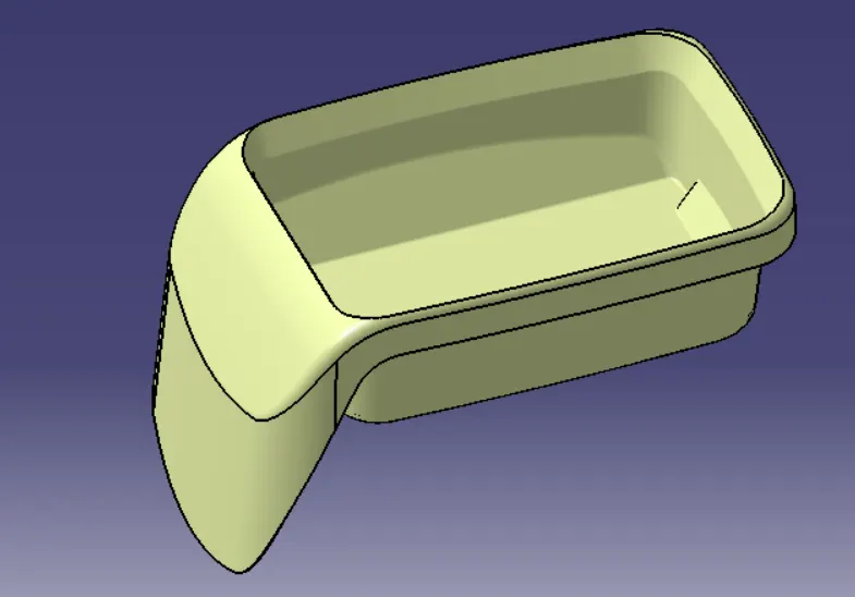
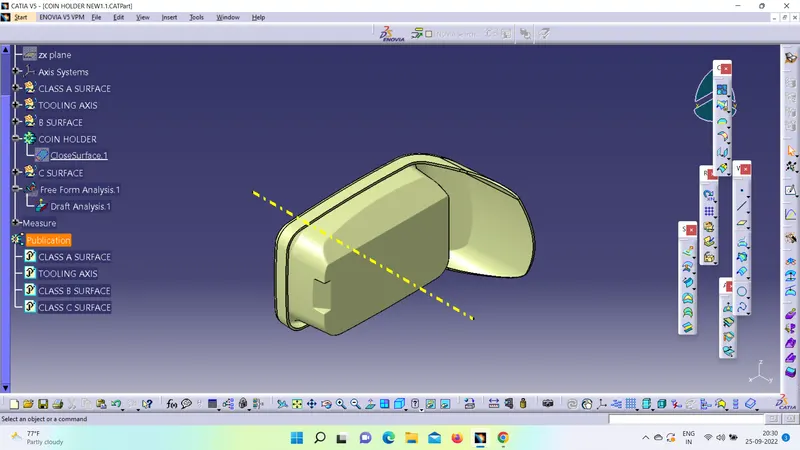
STEP 4 : Solid Body - Once the final close surface is created we have to shift to part workbench from surface workbench. In part workbench by using close surface commond the close surface will converted in to solid body.
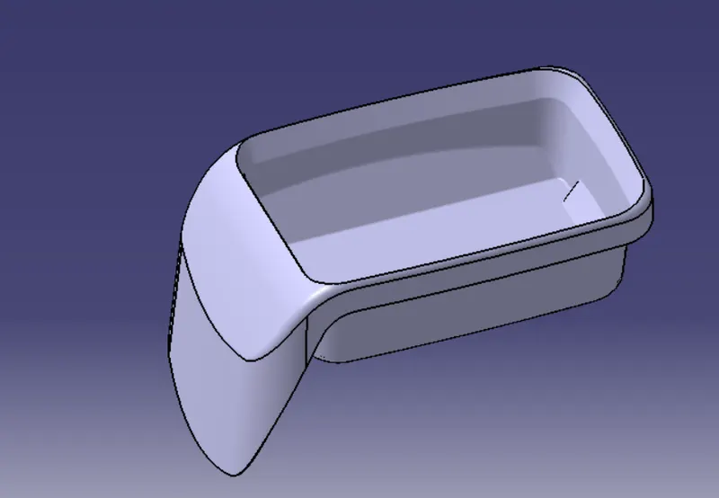
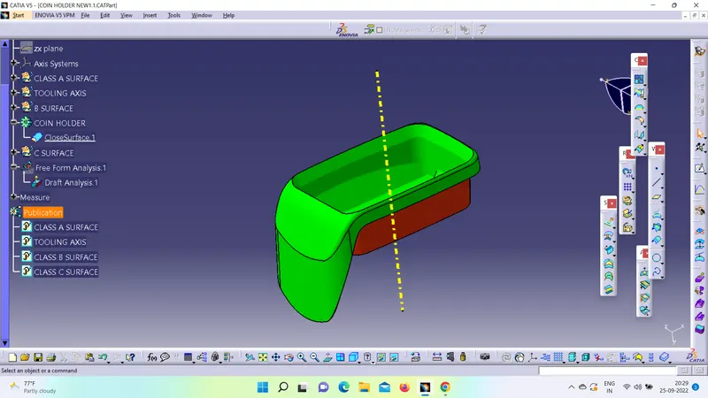
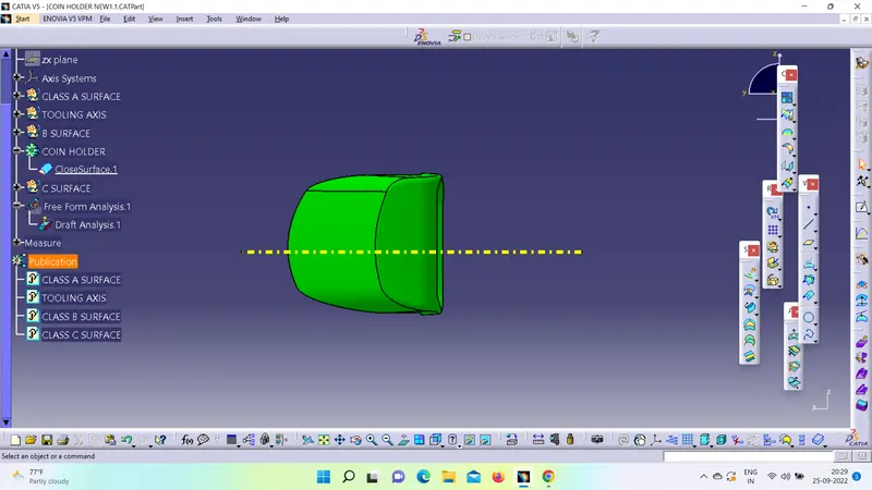
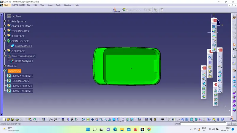
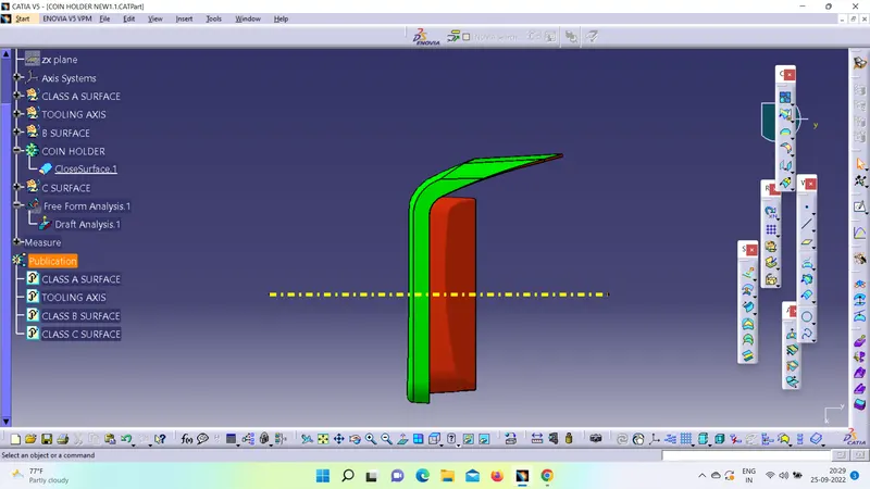
STEP 5 : Draft Analysis : It is very important to give draft angle to the plastic product to avoid damage or defective product output from the mould. The draft angle using in industries are 3 degree.
Drag the compus to the tooling axis and kept in center and then click on the compus icon on draft analysis dialogue box, the compus will get active. Once the compus will active again need to aligned along with tooling axis.
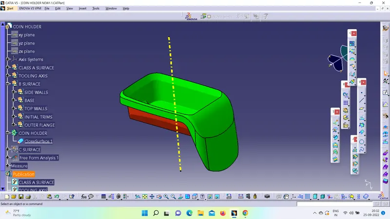
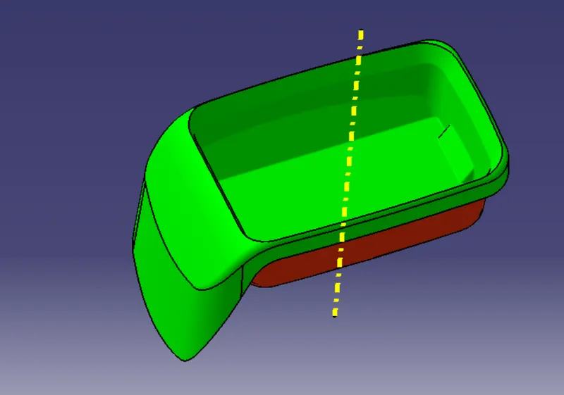
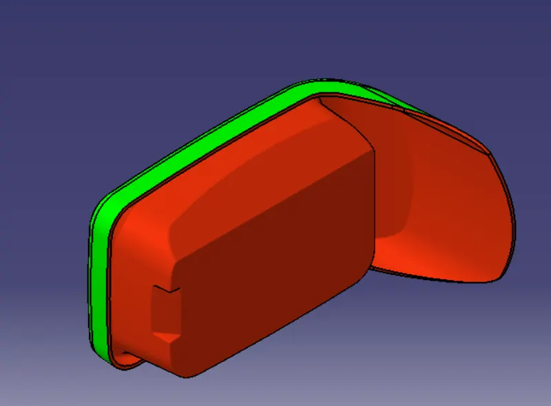
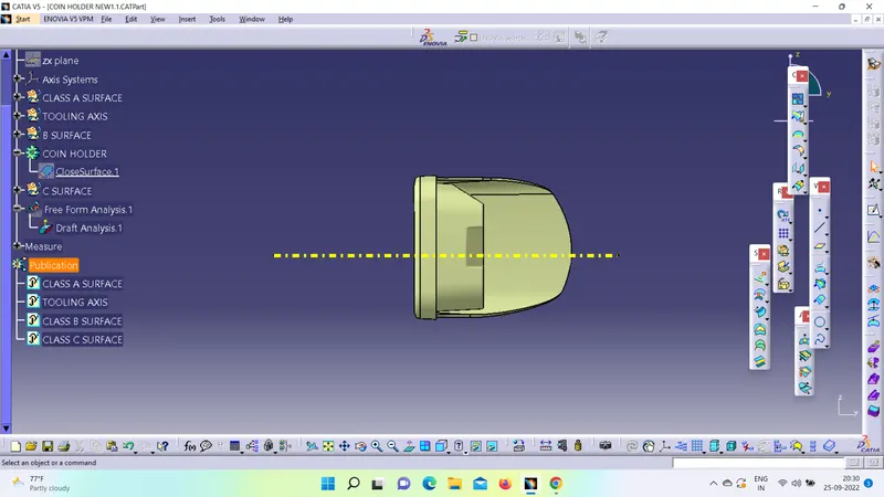
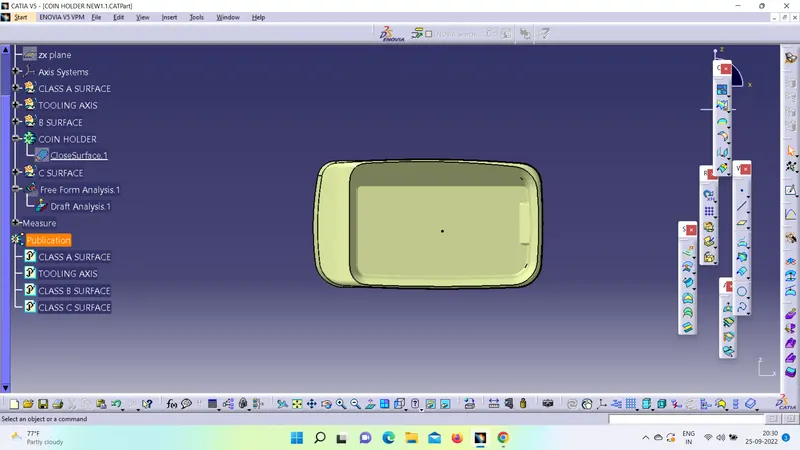
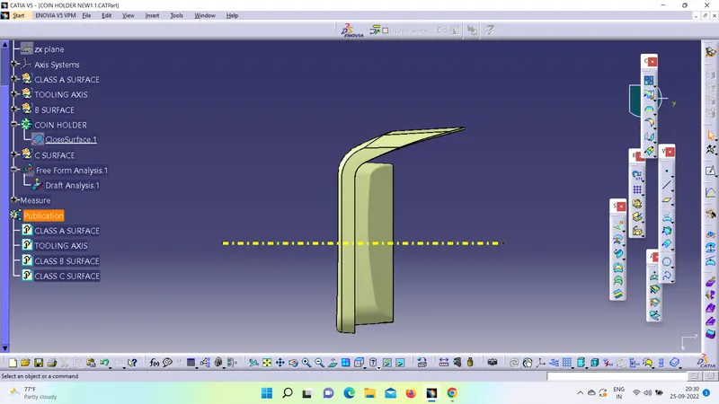
Once the compus aligned with tooling axis, click on the model to do the draft analysis, the model is convert into green color then its indicate model is perfect for modeling and if it is showing red in color then click on the draft analysis dialogue box in reverse icon and the model will get turn into green color, after click on reverse icon still the model is in red color the , don't proceed further , and revert back to class A surface engineer.
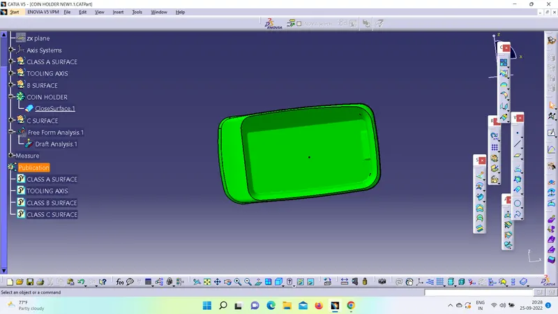
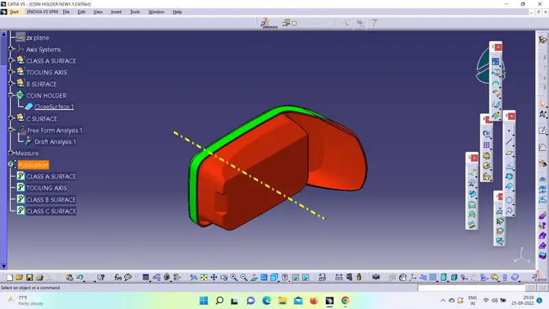
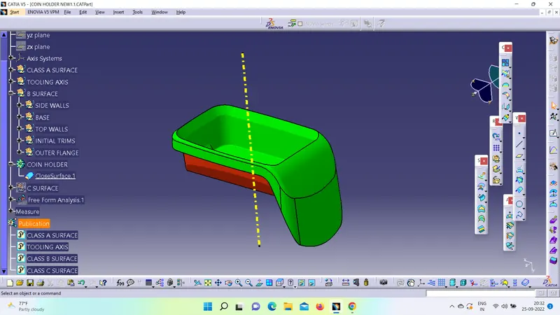
FEATURE TREE: