Roof Design
AIM - To create an assembly by developing the essential flanges for the outer roof and creating the reinforcements, give appropriate dimensions and check for Draft analysis as per given data and alsodo a curvature study on the roof and perform calculations to determine the position of the Bow-roofs.
INTRODUCTION -
Roof - An automobile roof or car top is the portion of an automobile that sits above the passenger compartment, protecting the vehicle occupants from sun, wind, rain, and other external elements. It also provides classic look to the automotive. Aluminium material is mainly used because of its light weight and good strength property.
Along with stylish aesthetics, there is also involved a lot of engineering behind the design of the roof
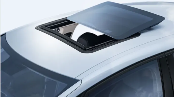
There are at least three types of roofs commonly installed on cars, namely sunroofs, moonroofs, and also panoramic roofs. Sunroofs are often even called moonroofs. The three are actually different in terms of use and benefits:
Sunroof- Sunroofs can be opened and closed using an electronic system. Sunroofs cars allow light, fresh air, or even both to enter the car cabin. It’s easier to imagine sunroof as a window on the car roof.
Commonly, sunroofs carry two types of panels made from the same solid metal used for the car ceiling exterior and can be pulled by hand to open the glass panel. Above it is colored glass which can be tilted backward to allow air from outside to enter the cabin.
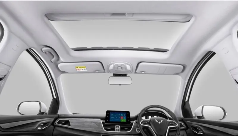
Moonroof - Moonroofs are actually one type of sunroofs. However, the material and uses are different. Moonroofs are made to allow the car driver and passengers to enjoy the outside view at night without having to get out of the car or open the car roof.
Moonroofs have colored glass panels that allow light and air to enter without having to shift the visor. However, lately, moonroofs are also equipped with a metal coating to keep the sunlight from entering directly into the cabin during the day.
Usually, the moonroof opens just slightly compared to the sunroof, so that air and light can enter into the cabin. However, there are a number of car manufacturers who now make moonroofs wide open just like sunroofs.
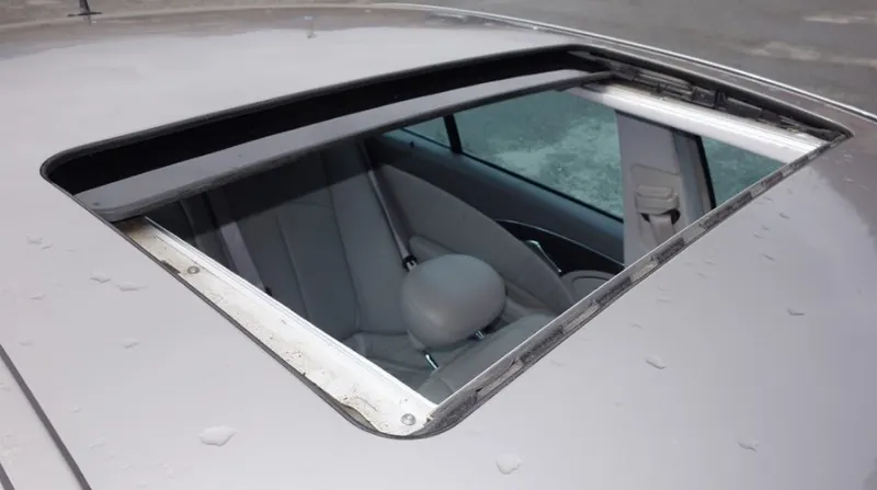
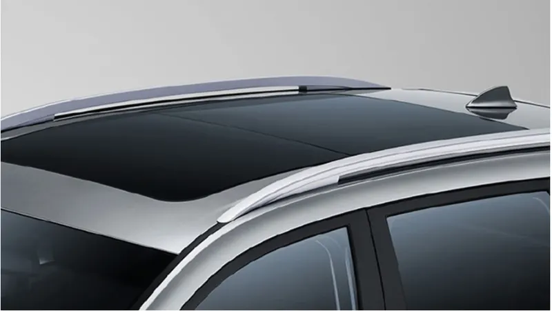
Panoramic Roof - In the last couple of years, the different kind of roofs, namely panoramic roofs is embedded in luxurious cars. Recently, the panoramic roofs have become increasingly popular in premium SUV's.
This type of car roof is generally similar to the moonroofs, which has a large glass panel stretching across the roof, right above the first to the second rows. The panoramic roofs can open wider compared to the moonroofs in general. Panoramic roofs also have coating blinds to keep the cabin cool when the glass layer is closed, but the view in the sky is still visible.
Components of Roof -
- The roof has an outer panel which is the styling part.
- Strengthening parts are present below an outer panel of a roof, which are front roof rail, Bow roof, Centre roof rail, and Rear roof rail.
- The front roof rail provides provision for the windshield glasses. Visibility criteria and headroom clearance have to be followed while designing the front roof rail. Provision for windshield mounting and inside rearview mirror is provided on the front roof rail.
- The Rear roof rail has hinge mounting for the back door. It is attached at the portion where the back door meets with the roof.
- Bow roofs are provided in between the front roof rail and center roof rail as well as the Rear roof rail and center roof rail. They are provided to enhance the localized strength of the roof and are attached directly to the bottom of the roof with either spot welding or with the help of Mastics.
- Reinforcement center or center roof rail is used as a cross member between Left hand and right-hand bodysides.
- Both the front roof rail and rear roof rail provided with the Master section for the design.
- The below image shows the location and Material used for all the strengthening parts.
Design and Functional Requirements for the Roof - While designing of roof following considerations have to be taken into account.
- Visibility Criteria
- Head clearance
- Curvature Study
- Head Distortion and snow load criteria
Roll Over Test On Roof -
- The rollover test is given by the Insurance Institute of highway safety ( IIHS). After analyzing many accidents IIHS has fixed some regulations about how to perform the test.
- IIHS rating is based on the following things which are how fast a car can reform its original shape after rollover and how deep a protrusion is.
- The aim of this test is to minimize the protrusion of the roof.
- Two conditions need to be followed while performing this test. One is to lock all the doors of the car properly and the second is to close all the windows of a car.
- Also, it is mandatory to fix the chassis on the hard lever surface horizontally.
- Load is applied at 25 degrees tilt when view from the front over the length of 762 mm.
- Load is applied at 5 degrees tilt when view from the side, over the length of 1829 mm.
Design Considerations -
- Clearance of 5 mm should be present between outer roof rail and Front roof rail, Rear roof rail, Bow roof, and Reinforcement center where mastics are used for adhesion.
- Thickness for all sheet metal parts - 0.75 mm.
- All edges should have fillets and there should not be any sharp edges present.
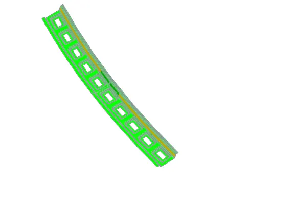
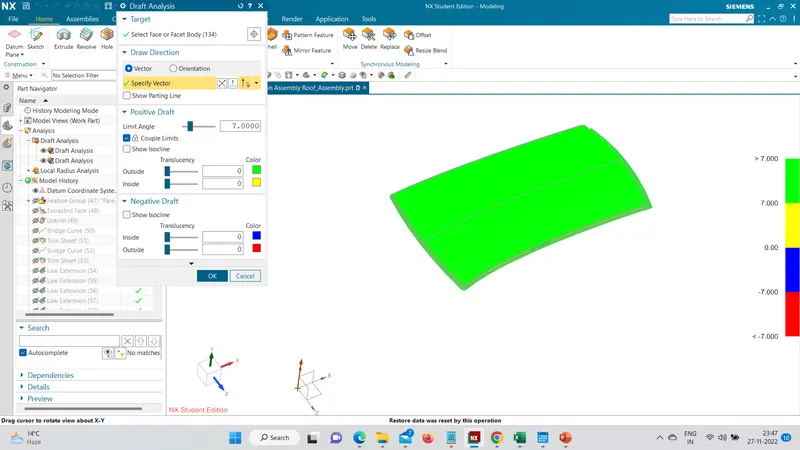
- A minimum draft of 7 degrees is required for all the faces.
Design of parts :
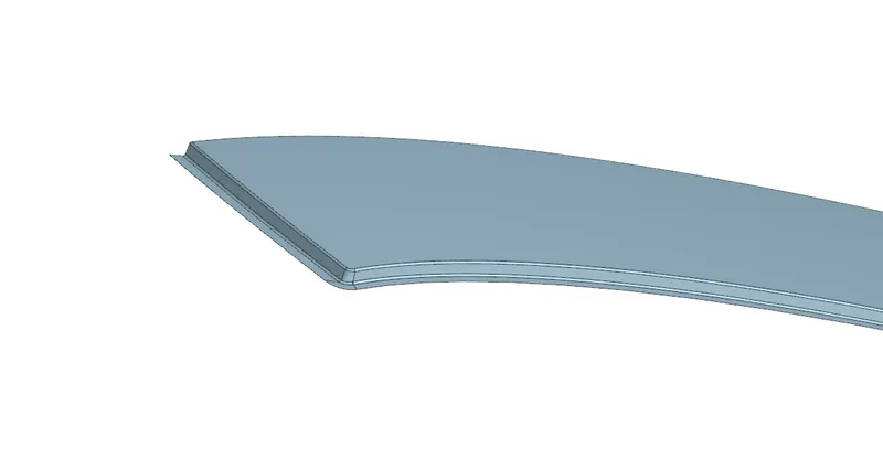
A. Outer Roof - We will take an extract from the class a surface and then trim it with respect to XY axis. Then we will create flanges on both the edges for front and rear roof rail. By using lawextension, bridge curve, trim sheet, untrim, through curve mesh, sew, edge blend to get the below one.
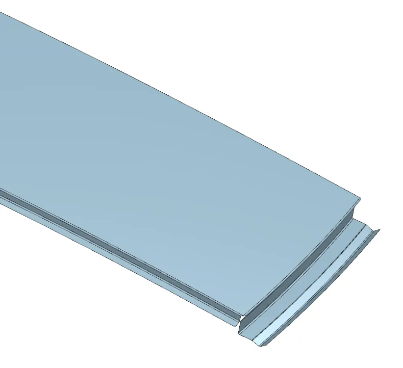
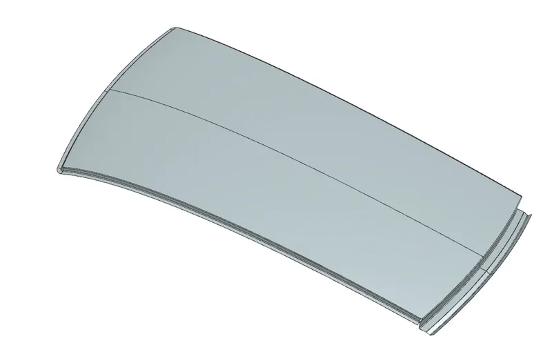
At the end, we will extend the surface in the XY direction and the trim it with respect to XY direction. In, the end, we will mirror it and sew and give thickness in the downward direction of 0.75mm.
B. Front Roof Rail - Front roof rail will have open at certain angle so that necessary thing like light, mirror can be easily mount. While designing of roof it is very important to provide minimum clearance to driver side i.e.
85mm minimum and it varies project to project. Small rubber kind material called as Mastics which is used to joint the roof outer and front roof rail.
The below image shows the dimensions used for the front roof rail.
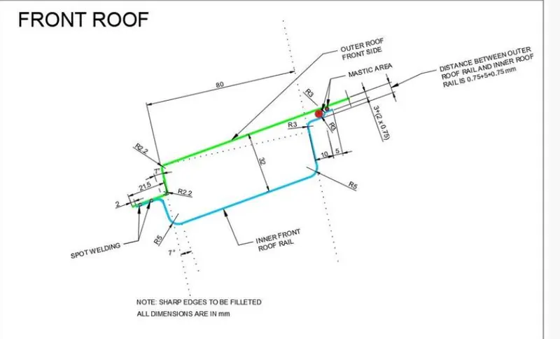
By following the above Master section and dimensions front roof rail has been designed. It is created with the help of an offset of 1.5 mm in the front as it will join the outer roof through spot welding and the rear side we have given an offset of 5mm+thickness i.e., 1.5mm(outer roof+front roof rail). All, the flanges are created with the help of law extension, edge blend, sew, mirror geometry, thickness, trim sheet, intersection curve, projected curve, extend sheet, emboss.
Embosses are given to improve the strength. They are created according to the manufacturing requirements. And cutouts are given to reduce the weight of the metal.
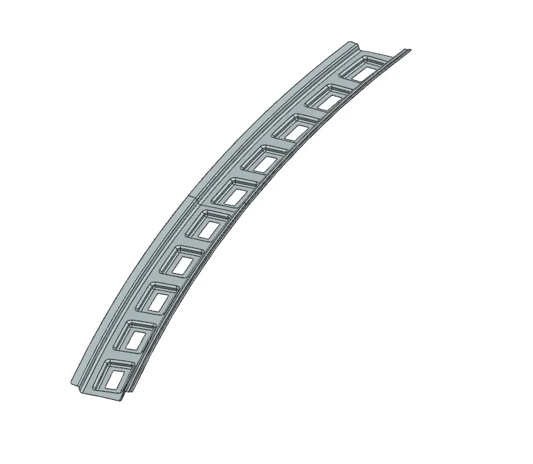
C. Rear Roof Rail - It is place where back door in mounted. It is very important to provide rear room head clearance & rear visibility criteria for safety and comfort.
By following the below Master section Bow Roof has been designed.
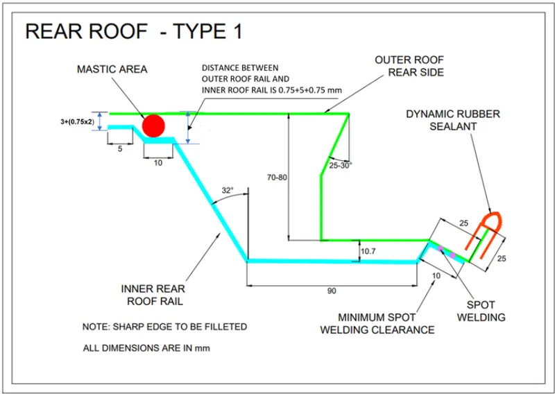
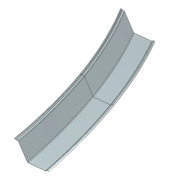
The below image shows thickened part of the Rear Roof Rail.
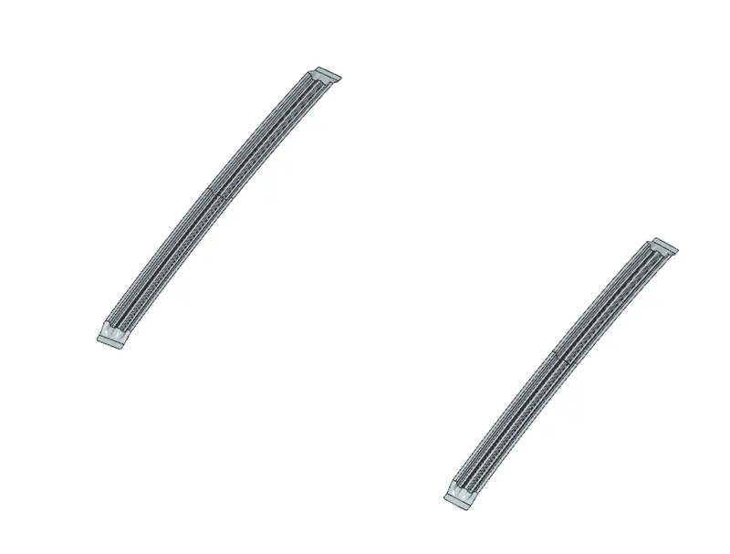
D. Bow Roof rail - These rails actually contribute to the strength of the roof these locations also play an important role in the strength of the roof. These are just joined by Mastics. The number of bow roofs depends on the length of the roof.
By following the given Master section Bow Roof has been designed:
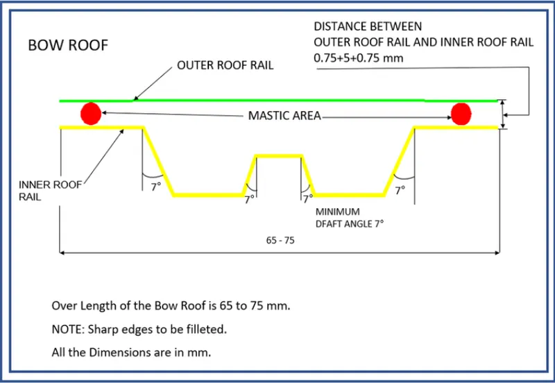
The below image shows thickened part of the Bow Roof.
E. Center Roof Rail - The center roof rail lied between front and rear roof rail, provides proper balance to the roof and also provides area for mounting of light. It has also some mastic region and embosses area and reinforcement region
By following the given Master section Centre Reinforcement Rail has been designed:
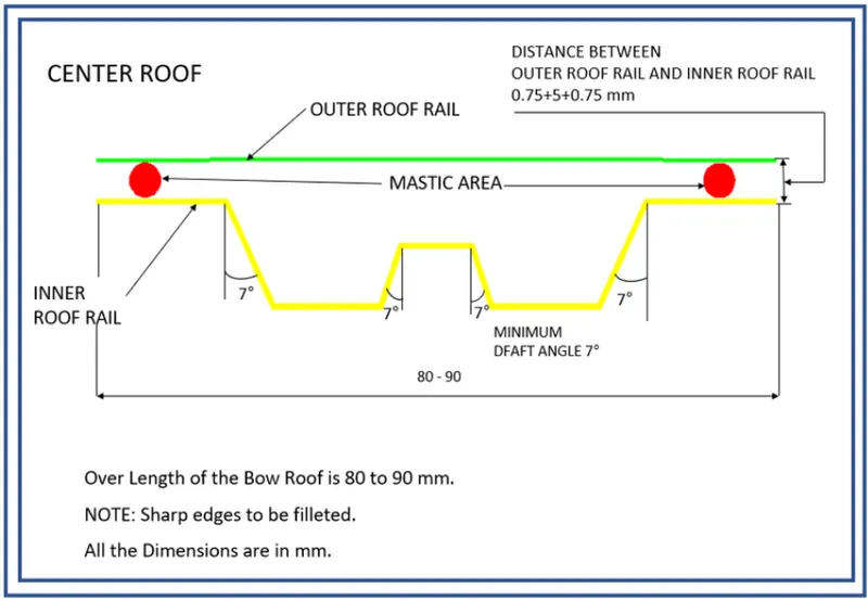
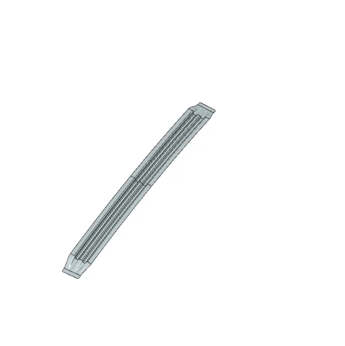
The below image shows thickened part of the Centre Reinforcement-
Joining & Assembly - For joining here mastic and welding technique is used, generally spot welding is preferred. After completing assembly it goes to Role Over Test which is very important to check the impact bearing capacity.
Roof Curvature Study - There are 2 conditions for the roof test namely Heat distortion and the Snow load test.
A) Heat Distortion Analysis
- Heat distortion analysis plays a pivotal role in the strength of the roof panel. It is the temperature above which material cannot be used for structural applications.
- This study is used to predict the heat distortion temperature where the material starts to soften when exposed to a fixed load at elevated temperature.
- In order to avoid any bending or damages on the roof, heat distortion temperature can be recalculated using the trial and error method by changing the position of bow roofs. In this way, it can come in the range which is shown below.
Formula
W = [1.73 x 10^(-3) x L] + [1.85 x 10^(-8) x (R^2)/t] + [ 1.10x10^(-3) x l] - 2.68
Judgement Condition using W: OK< 2.68
Where
L = Roof Length in X-Direction[mm](Roof dimension in 0-Y)
R = Roof curvature
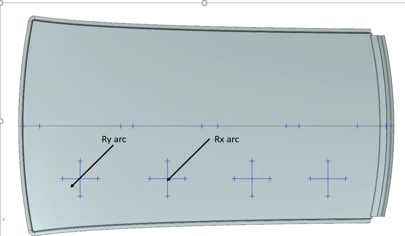
R = 2(Rx*Ry)/(Rx+Ry)
Rx = X curvature
Ry = Y curvature
t = Roof plate thickness [mm]
l = Bow Roof Span [mm]
Annotations:
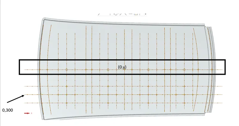
Drawing of Arcs to find out Values for Rx and Ry
Calculations

B. Snowload Analysis
- The purpose behind this analysis is to check the strength of the roof when snow is present on it acting as a load.
- A roof should be designed in such a way that it should rebound to its original shape after the removal of snow.
Formula
Qr = [Iy x t2] / [α x s x [(Rx + Ry)/2]2 x 10-8]
Where
α = My x Lx2 x 10-12 , My = Y(Ly-Y)
Judgement condition = Qr ≥ 3.1
250 ≤ s ≤ 380
t = Roof plate thickness [mm]
Ly = Distance between the front and rear roof Rails on the Vehicle along with 0Y[mm]
Length of Roof panel with the center point between Roof rail Front /Rear as the front and rear reference point.
Lx = Distance between the Left and Right end of the roof on the Roof BOW [mm]
Width of the roof panel exposed on the surface.
Y = Distance front Front Roof Rail to Roof BOW[mm]
s = Distance for which Roof BOW bears divided load [mm]
s = L1/2 + L2/2
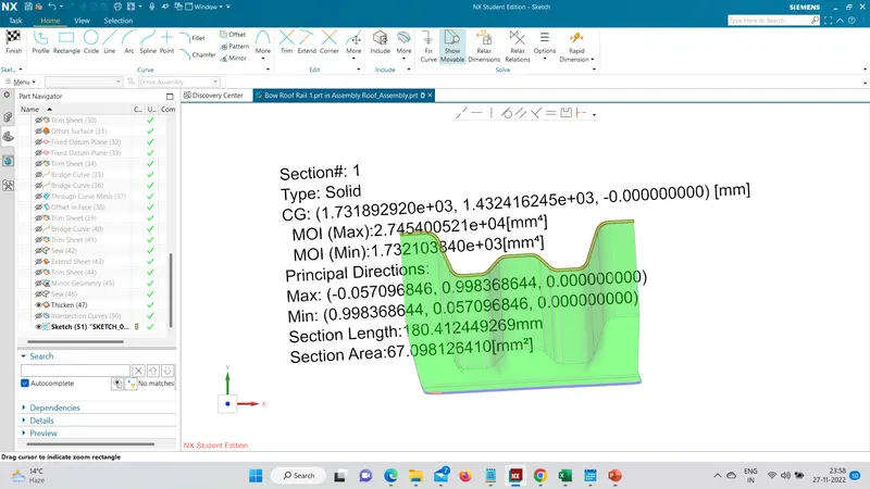
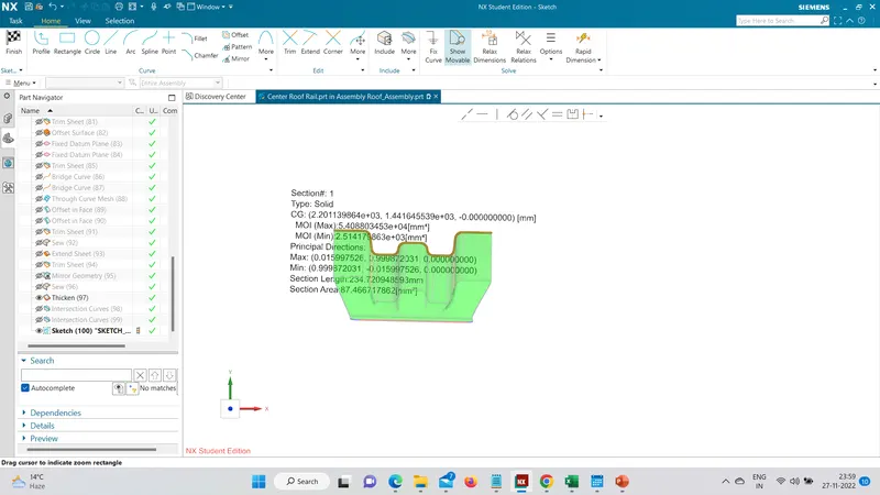
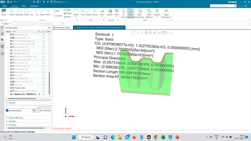
Iy = Geometrical moment of inertia of Roof BOW (Y cross-section )[mm4]
Rx = Lateral direction curvature radius of roof panel Y cross-section on Roof BOW [mm]
Roof panel curvature Radius of the Length Lx in Front view
Ry = Longitudinal Direction curvature radius of the Roof panel X cross-section on Roof BOW [mm]
Roof panel X curvature radius of length s in Side view
Annotations
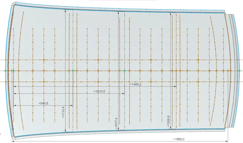
Drawing of Arcs to find out Values for Rx and Ry
Moment Of Inertia -
A. Bow Roof Rail 1 -
B. Center Roof Rail -
C. Bow Roof Rail 2-
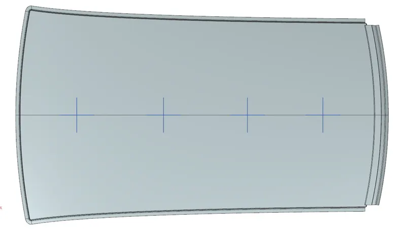
Calculations

Note - We will not consider the value for the 4th one as the value of S will be zero for 4th case.
Draft Analysis -
A.Front Roof Rail -All the faces of Front Roof Rail have successfully cleared the draft analysis with a minimum draft angle of 7 degrees.
B.Outer Roof - All the faces of Roof have successfully cleared the draft analysis with a minimum draft angle of 7 degrees.
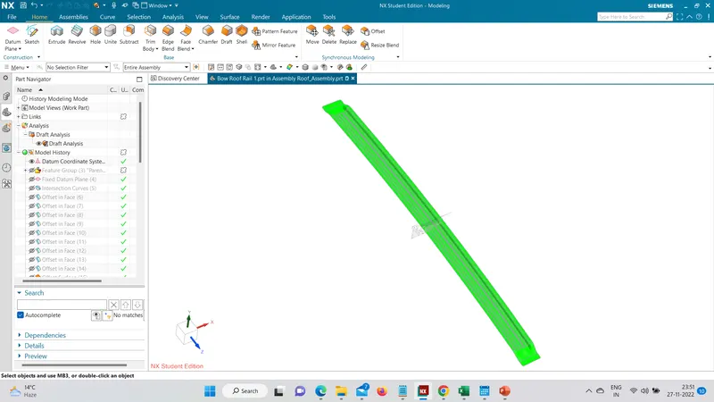
c. Bow Roof Rail 1 - All the faces of Rail have successfully cleared the draft analysis with a minimum draft angle of 7 degrees.
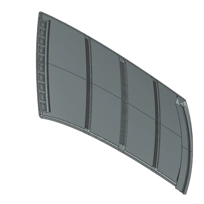
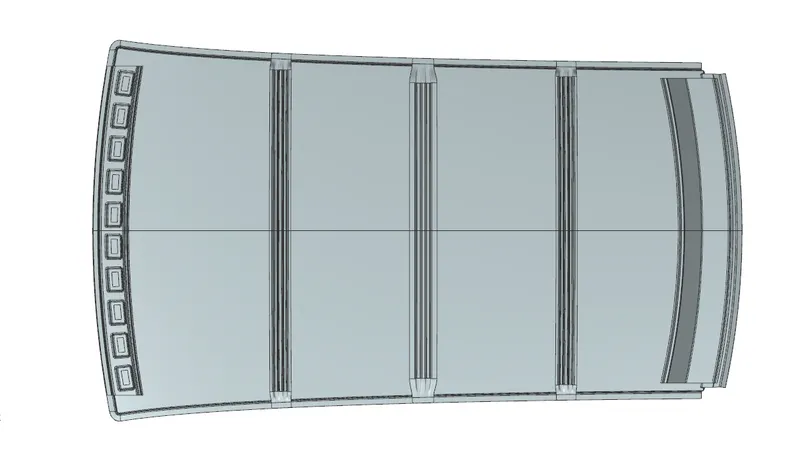
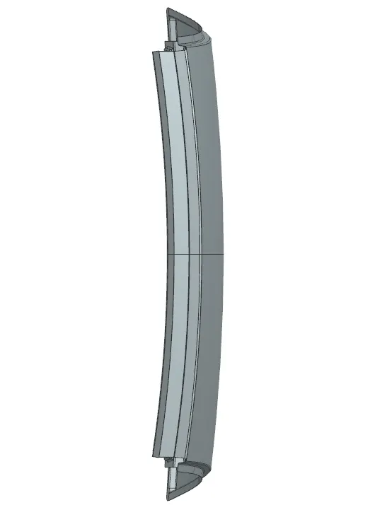
ASSEMBLY VIEWS -
Isometric View:
Top View -
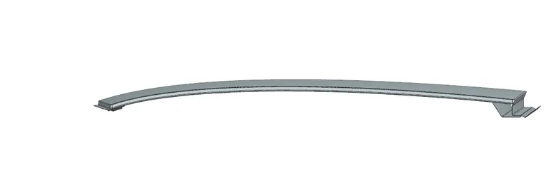
Front View:
Right View:
RESULT -
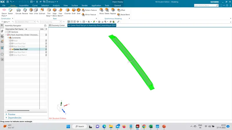
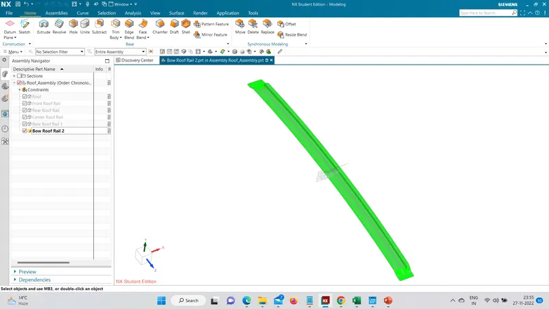
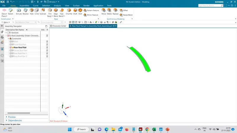
- All the parts have successfully cleared the draft analysis.
- The proposed Roof design has successfully cleared the heat distortion analysis.
- The portion between bow roof 1 and Rear Roof Rail is failing in Snowload analysis.
- Embosses have been provided onto the roof outer panel portion where it is failing in snowload analysis. Embosses increase the strength of the roof panel.
CONCLUSION -
The roof has been successfully designed considering all the design Rules, Master sections, Manufacturing feasibility, Draft analysis, Heat distortion criteria and snowload analysis.