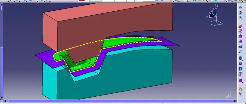
Week 8 - Challenge 5 - Core & Cavity Design
OBJECTIVE:
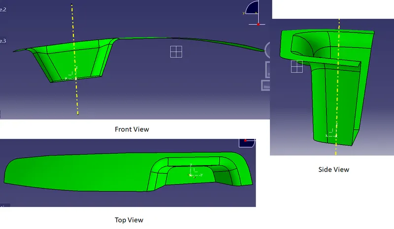
This is to generate Parting surface and Parting line for the SWITCH BEZEL along the tooling direction.To tha same part we have to create tooling axis,Class B and C surfaces to generate solid part body. And the draft analyisis on the same body.
A Detailed Geometrical Sets is provided below for which we have followed all the methods to generate.
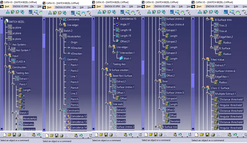
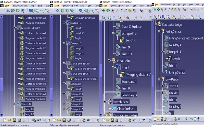
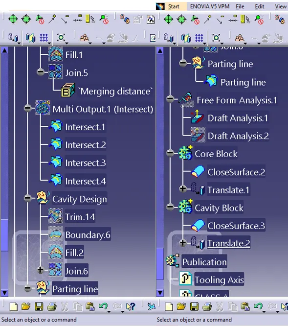
STEP 1 : Tooling axis creation
As we have 3 walls of the handle, we have to perform the Bisection method to get the tooling axis.
First a point is created in the base with Point - direction Command on the base surface which is extracted form class A surface.
Then by intersection method on the Y direction will create an bisecting line.
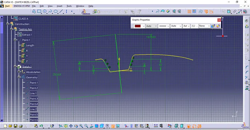
And the same is continued on the X direction also
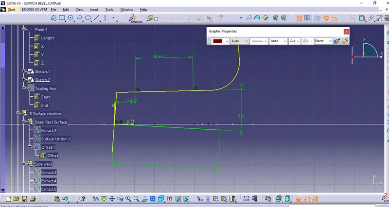
With these two lines with Bisecting method, we have achieved the tooling axis
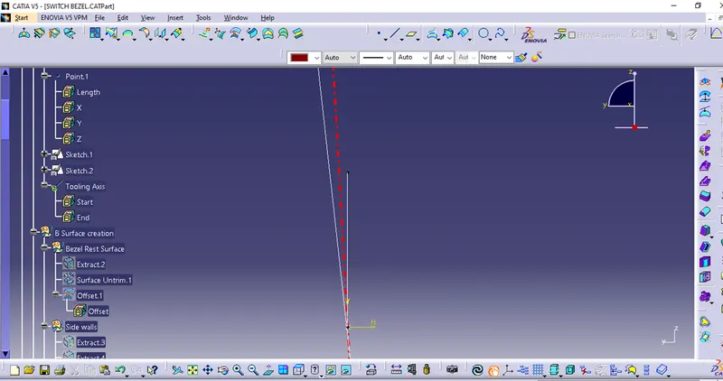
STEP 2: Draft analysis on the Class A Surface
On selecting class, A surface performed the draft analysis along the tooling axis, we have got the following results.
Draft analysis in different orientations
ISOMETRIC VIEW
And Other Orientations
STEP 3 : Creation of B surface from class A surface
From the Class A surface step by step all the surfaces are extracted and them Untrimmed
and extrapolated with approximate length
Them Offset each surface by 2.5 mm by hiding the parent plane
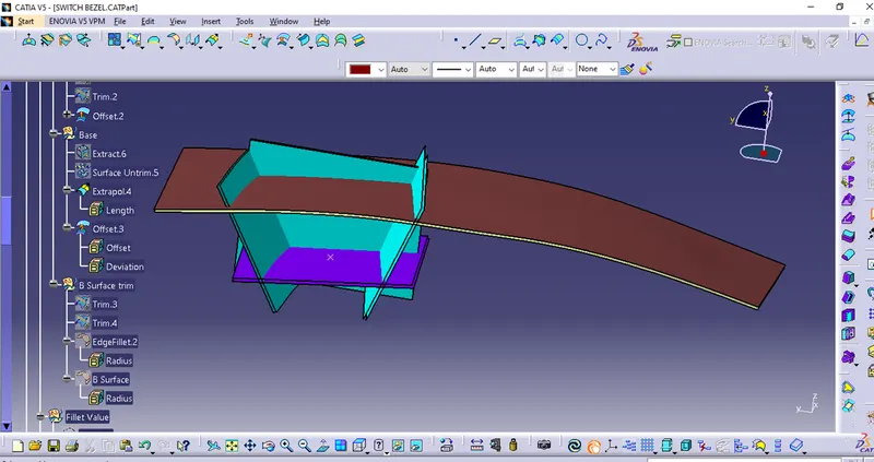
All the Ofsted planes re trimmed to get an appropriate B surface
For Side wall corners an fillet value of 17.5 is given and the top corners 11.5mm had given to get the Uniform wall thickness.
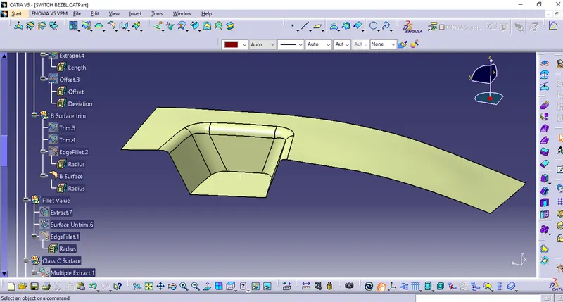
STEP 3 : Creation of C surface from class A surface
Then next step to crate the C surface, from class surface extract the boundaries with Multiple extract command.
Then SWEEP the boundary with minimum Draft angle 3mm. as the surface has lot of disturbing lines make the surface smooth with smooth command with the minimum value of 0.001mm.
Then by checking the boundaries if it satisfies with a single boundary condition with the smooth curve value with maxium 0.003mm, with all trials a class C is created along the tooling direction.
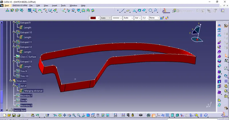
For this particular case the object is not satisfying the boundary command with the maximum smooth curve value 0.003mm, so to avoid this we have extrapolated the class surface by a minimul value of 0.5 mm then replace this trimmed surface with the class surface then trimmed with class C surface.
Joining od Class C surface with Class A surface.
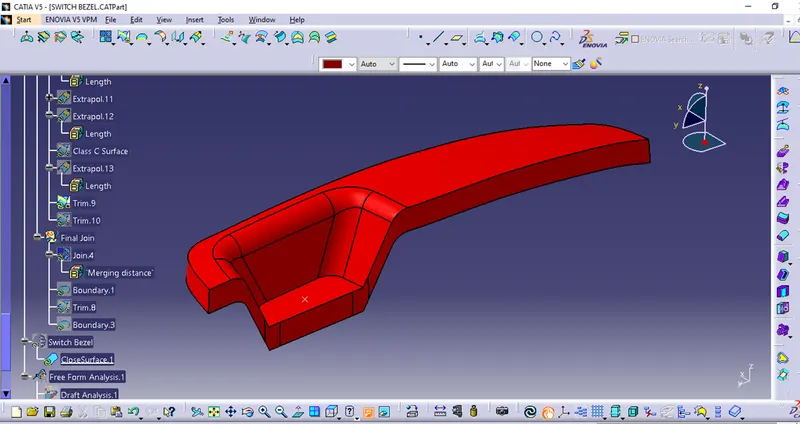
STEP 4 :Final Joining and Closed Body
Now we have all the three surfaces A,B and C
We have already joined Class A and C surfaces so by final trimming of these surfaces with B surface will give us the final Surface Body.
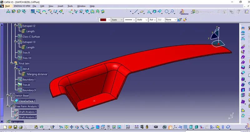
Then in the part workbench make the surface part to part body with thickening option.
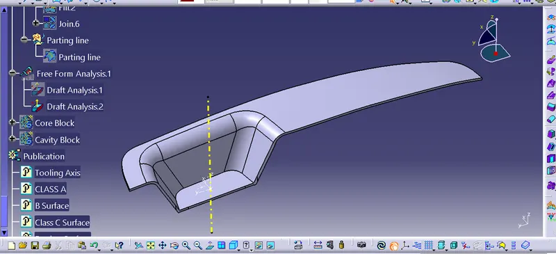
STEP 5 : Draft analysis on the part body
In the same wat we have performed Draft analysis on the class A surface we will also perform the draft analysis on the part body also long the tooling axis.
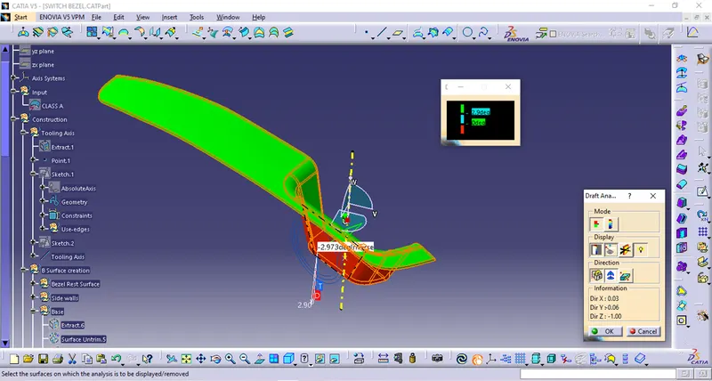
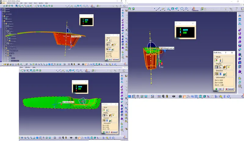
STEP 6 : Core cavity design
First Will create Parting surface.
Fromt the earlier Class A, B and C
First extrapolate class A surface by around 10mm trim with Class C surface.Then trim with B aurface.
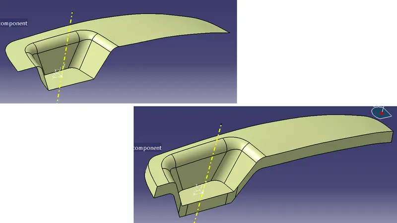
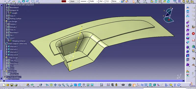
CORE DESIGN
From the Parting surface By cerating a rectangle along the the part boundary extruded with double the part thickness and trim it with the parting surface.And make it solid will give us the Core.
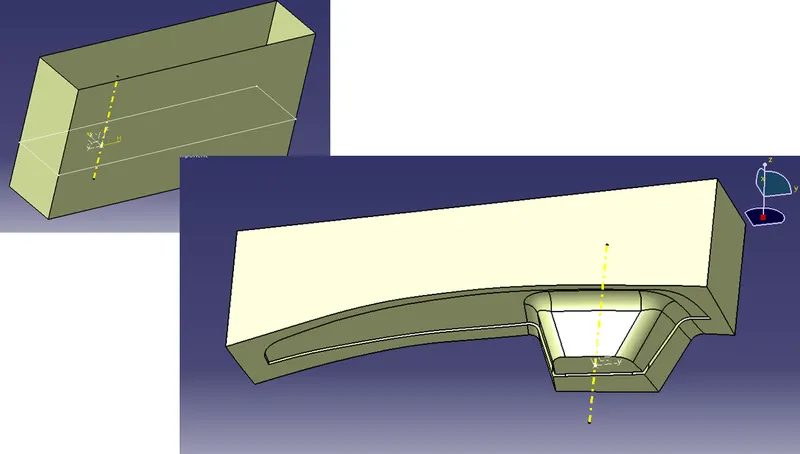
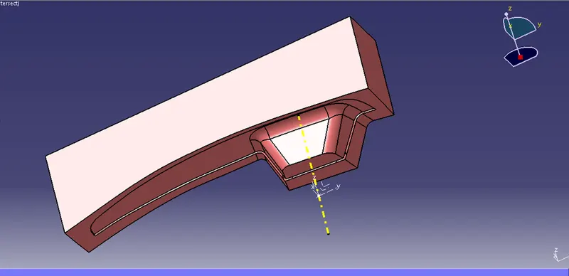
CAVITY DESIGN
In the same way the B surface is trimmed with the extrusion will give us hte cavity, and in the part body will get a soid Cavity body.
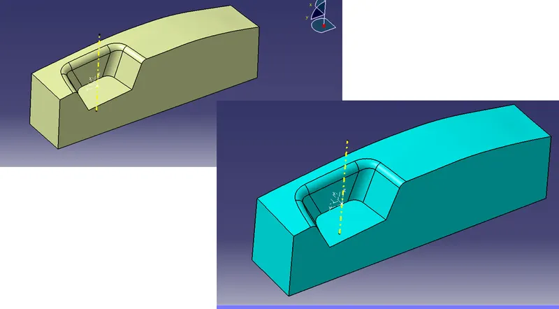
Parting Line:
Parting line is the ingtersection line between the body extreme and the prting surface.
Here we have Intersected the parting surface with B Surface is our parting line.
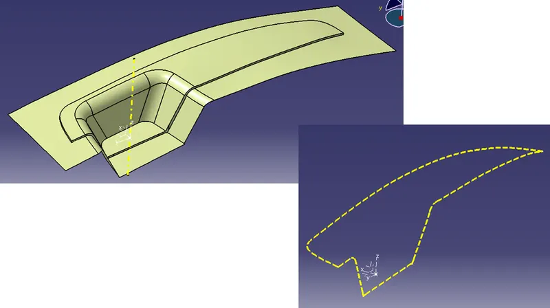
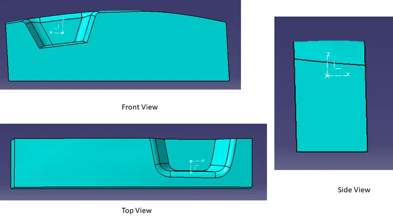
CORE AND CAVITY BODIES IN DIFFERENT VIEWS
CORE
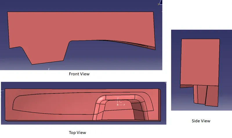
CAVITY
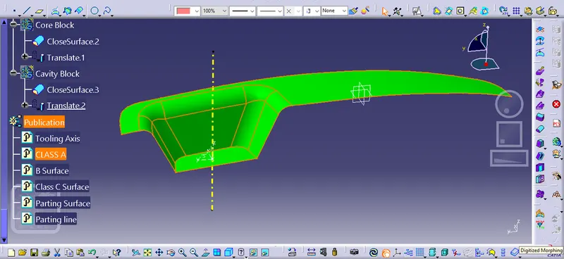
PUBLICATION:
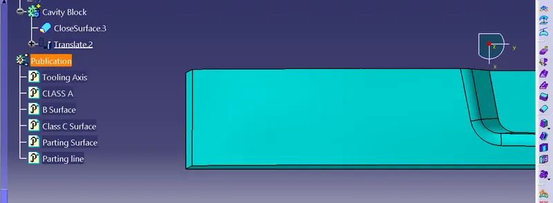
We have Published Tooling axis,Class A,B and C surfaecs,Perting Surface and aprting line.
ALL THE END RESULTS IN ONE IMAGE