Design of backdoor
OBJECTIVE:
Extracting the inner panel model from the given class A surface with all the design and mounting consideraions. And creation of all reinforcements at all the required position, finally draft analysis along the tooling direction.
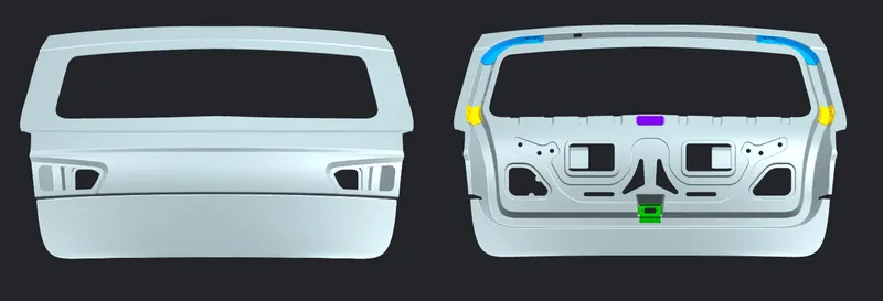
History of Back Door
The door or opening of a cargo area may be hinged at the top, side, or bottom.
If the door is hinged at the bottom it is called a tailgate, particularly in the United States. They are used on station wagons and pickup trucks, as well as on some sport utility vehicles (SUV). Traditional drop-down station wagon and pickup tailgates can also serve as a mount for a workbench.
Traditional U.S. station wagons included a roll down window retracting into the tailgate to load small items or to allow the tailgate to be opened down on its bottom mounted hinges. Because of the potential for carbon-monoxide fumes, the tailgate window on station wagons should be closed whenever the engine is running.
Two-way station wagon tailgates may be hinged at the side and the bottom so they can be opened sideways like a regular door, or drop downwards as load platform extenders. They are designed with special handle(s) for opening in the selected direction on special hinges after the window is lowered.
A three-way design that was also used by Ford allows for the tailgate to be opened like a door with the window up.
General Motors developed a clam shell style "disappearing" design where the rear window rolls up into the roof and the tailgate slides down and beneath the load floor.
If the door is hinged at the top it is termed a hatch, and is used on a hatchback. A bottom opening door is now common on SUVs
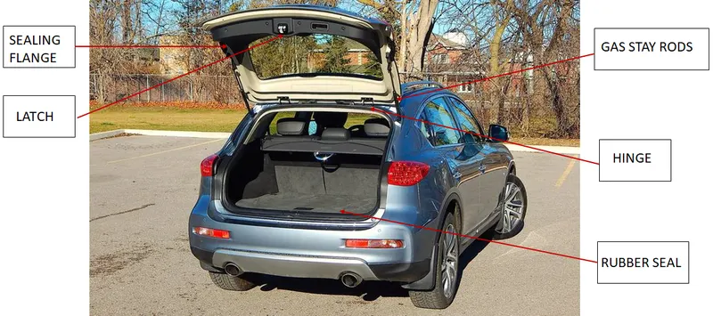
Following are the steps we have followed to obtain the desired model.
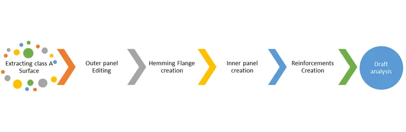
OUTER PANEL EDITING:
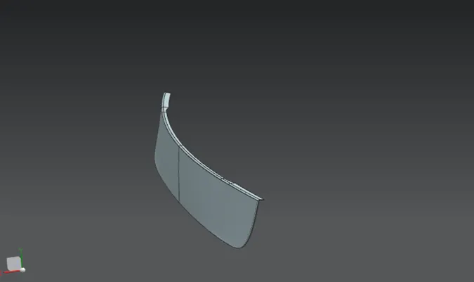
All the given Class A surfaces are perfect, so inorder to make usre the surface is proper we do ckeck all the edges if they are not, will make changes acordingly.
Once the basic surface is ready will maka a copy of it, to work on.
As the surface is not possible to manufacture in single pass, we have devided it in two parts
- Back door outer upper surface
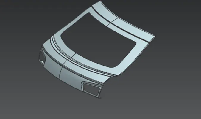
- Back door outer lower surface
HEMMING:
Inorder to fix the outer panel with the inner panel we need to join them with the hemming flange.
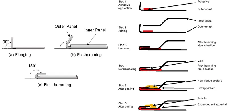
For the hemming flange creation we have offset the oiter surface by 2.65 mm considered required gap in between the sheets.
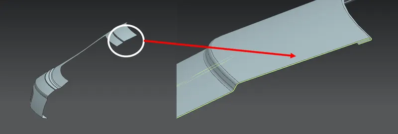
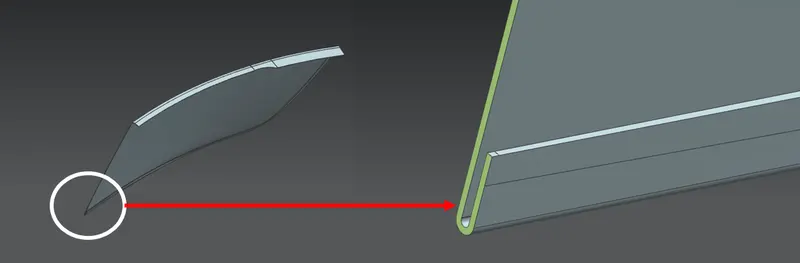
We have made the hemming seperately for upper and lower panel.
Back door upper panel hemming
Back door lower panel hemming
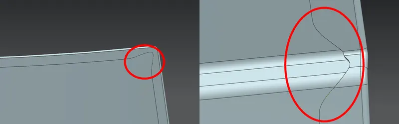
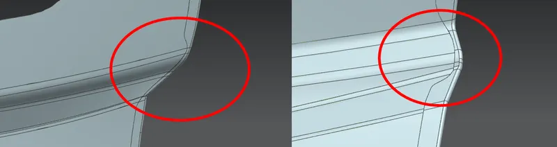
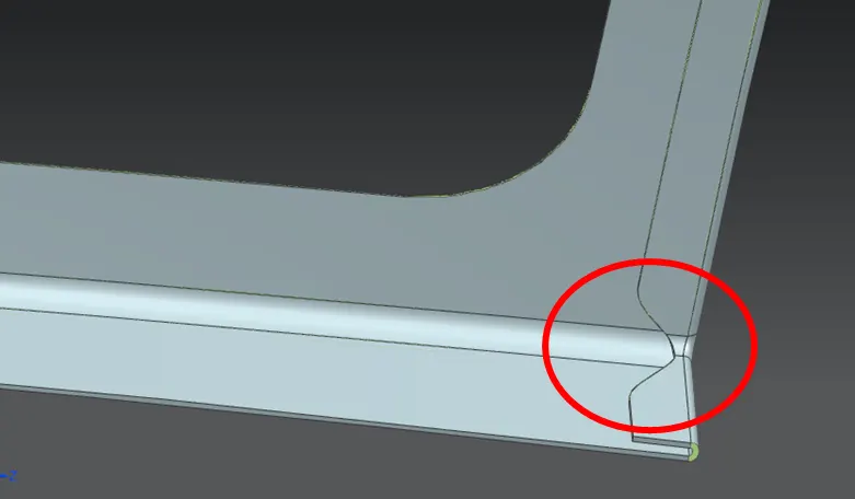
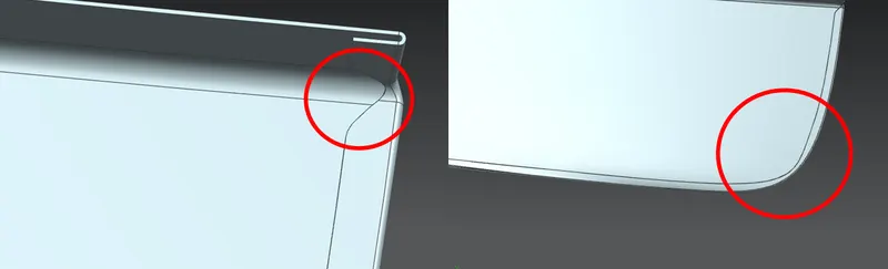
In hemming we have to consider one most importent thing, that is corners reliefs.
These are very importent while manufacturing, if we dont provide corner relief which will damahe the part.
Following are the images after corners relief at different criticle positions, and we thickened part by 0.75mm.
Back door upper panel corner reliefs
Back door lower panel corner reliefs
BACK DOOR INNER PANEL:
Inner panel is the one of the key factors of the back door design, it should give ample space for boot space.
With all the required mountings provision, it one of the major role during crash.and it should not send any of the forces to the cabin.
We remove some material in order to save the cost on material, by not compramising on quality and strength.
Some if the portions where the extra meterial is add to increase the part strength and for assembly constraints.
Back Door inner panel modeling having the following steps
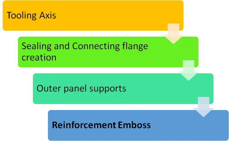
Tooling axis
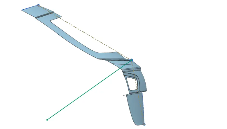
All the models that are designed need to manufacture, so that all the suraces in the model should follow one direction which easy to draw any part, that is tooling direcion.
We have considered the two extreme edges of the face drawn a line took a intesection line which is our tooling axis.
From now on all the operation we perform on the surface should follow the tooling axis. which enables us the easy manufacturability of the part.
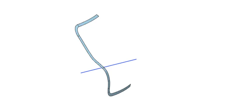
Sealing flange and Connecting flange creation:
In consideration with ample boot space with maximum strength we desode on the sealing flange length.
With seals the surface between the body side panels with back door, in order to resist for all the weather conditions.
This sealing flange is obtained from the offset surface, which inturn off set from the outer panel by 25 mm with clerance.
This flange is the outer most part on the back door inner panel, then alternatively we do generate the remaining flanges and surfaces by using proper tools in the NX cad software.
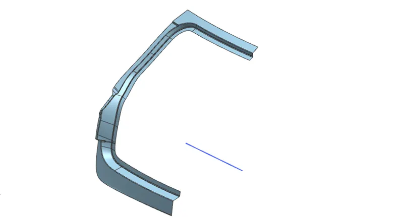
Outer panel Supports:
Where there is more gap between the outer panel and the inner panel we have given support which is a cutout of the inner panel, which increase stability between the arts while moving.
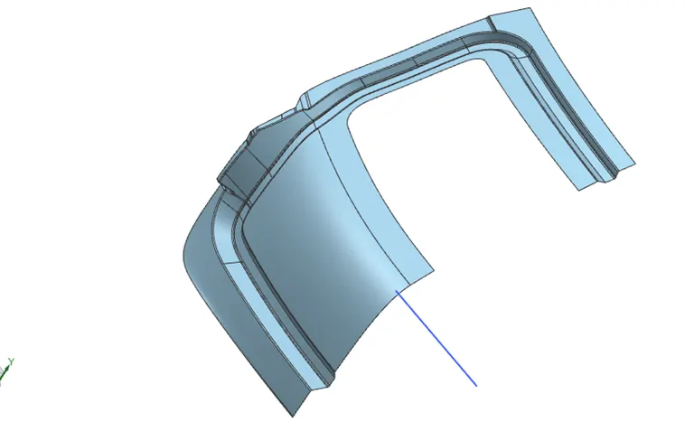
Side flange
Rear windsheild flange and Inner panel
Cutouts and embosses:
As the solid surface of the door will not results us with good efficiency vehicle.
So the areas which are not in use are notmally trimmed of, which inturn increase the vehicle performance by redusing the weight, and reduses the raw material cost.
Following images shows the trimmed off surface with proper embosses.
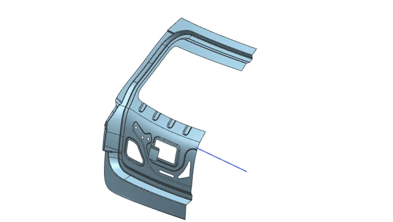
After thicning the surface by 0.75 mm willl complete the inner panel design.
Reinforcement Emboss:
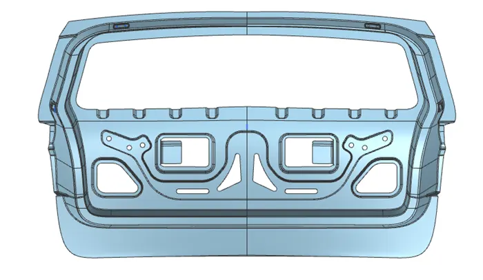
Inorder to extrace the reinforcements from the surface we have created embosses and are extracted later , except Latch and wiper motor reinforcements are to be created after the surface mirrored.
Following are the images of reinforcement cut outs.
Hinge:
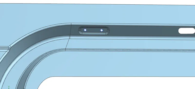
Gas stay:
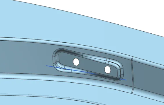
Wiper motor:
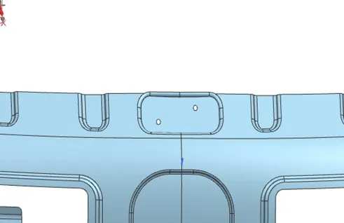
Latch mounting:
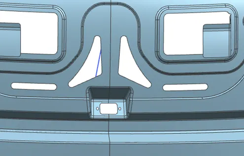
Outer panel support:
Which holds the outer panel firmly, in all the conditions.
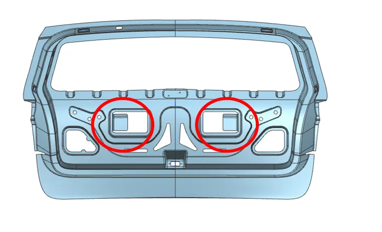
Support for the latch controller:
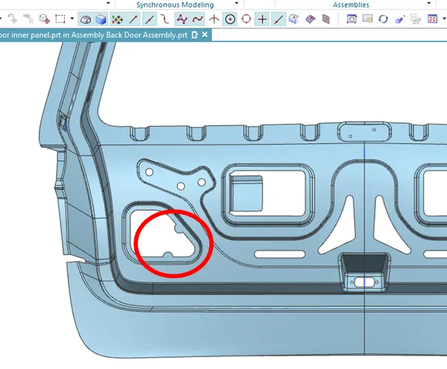
Back door Plastic panel mouting :
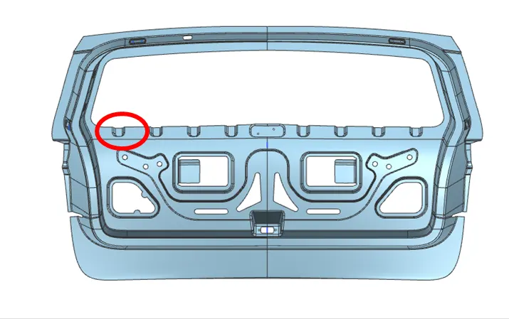
Provision for weather control strip for the glass
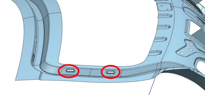
Provision for rear door Wiring
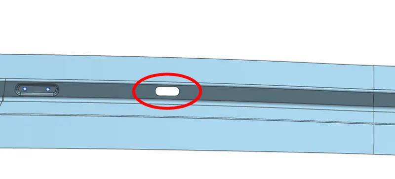
REINFORCEMENTS:
Once bothe inner panel and outer panel is ready, whick need to fixed at some points on the same panel.
For that we need some reinforcements, with adds additional sterngth to the part.
Following are the reinforcements
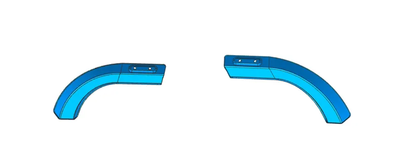
- Hinge reinforcement asssembly
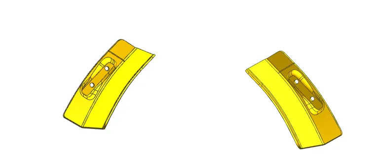
- Gas stay reinforcement assembly
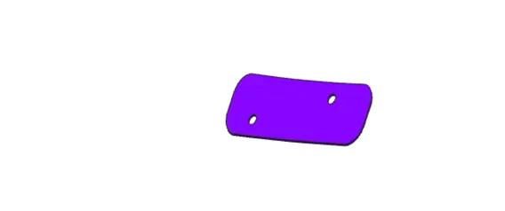
- Wiper motor reinforcement
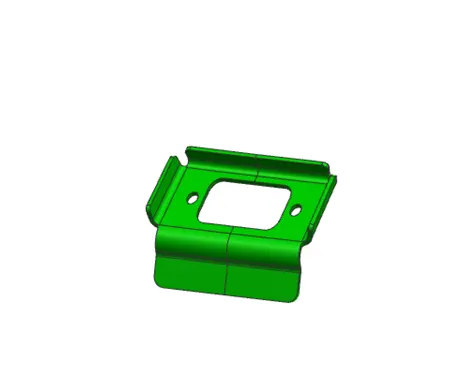
- Latch reinforcement
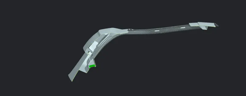
All the reinfrocements are extracted from the inner panel, and trimmed to the desired size.
Which are then thickned by 2 mm, these reinforcements are attached by spot welding to the inner panel.
Following are the corresponding images.
Hinge reinforcement asssembly
Gas stay reinforcement assembly
Wiper motor reinforcement
Latch reinforcement
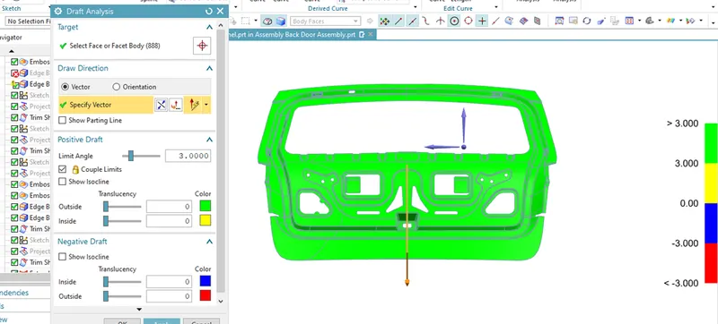
DRAFT ANALYSIS:
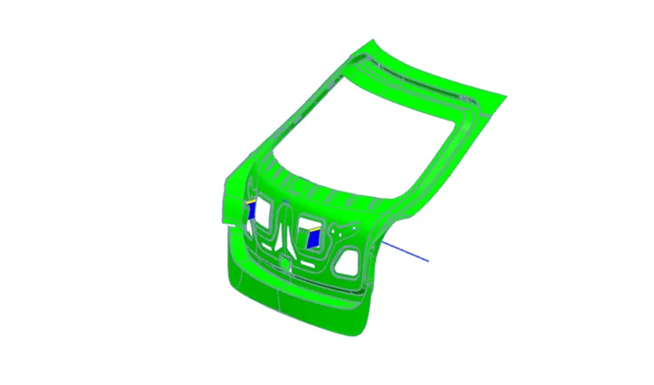
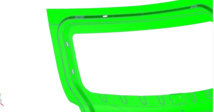
Once everything is done we need to know weather our designing the tooling axis or not will be abae to know from draft analysis.
Which shows all the surfaces, from it will change or modify the other surfaces to follow the diresctin.
Which completes the designing and analysis of Back door
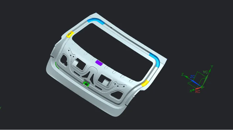
Following images will show us the draft analysis results.
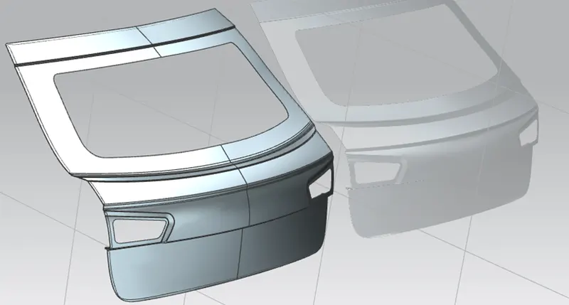
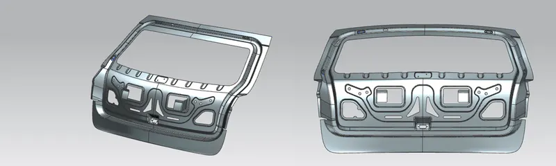
Some of the final rendering images in different orientations.
Conclusion:
Herewith we conclude that we have created inner panel from the given class A surfaece,with all the reinforcement, and all the prior surfacess following the tooling axis.