Week 9 - Project 1 - Door Applique Design with Engineering Features
OBJECTIVE:
To design a Door Applique with all the engineering features to be following all the Design rules of making solid part body form class A surface and attaching both locators and Heat strakes to it and performing thr draft analysis on the final body.
And also providing slots on the Door attachement surface.
TOOLING AXIS:
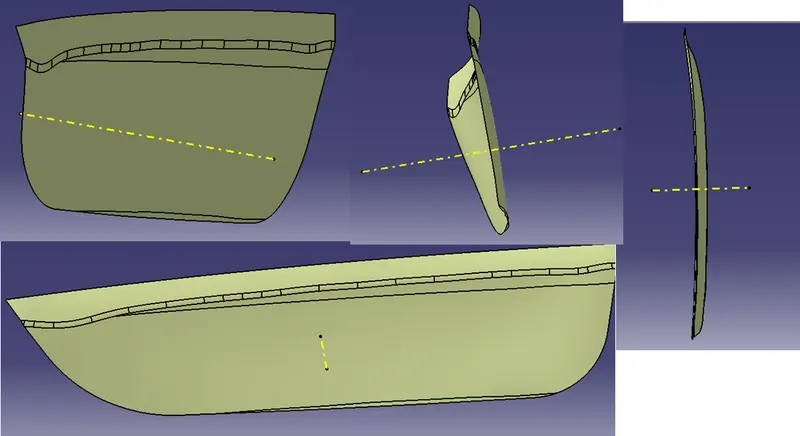
To start any thing we have to first create Tooling Axis which heps us to do all the operations along it, to avoid manufacturing errors later.
In the perticular Class surface is almost flat so i have created a linr normal to the surface which is our tooling axis.
DRAFT ANALYSIS:
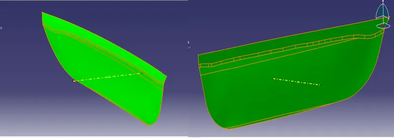
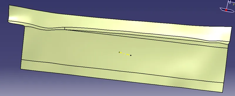
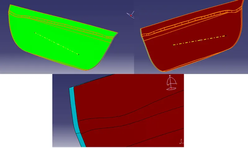
Once after we the tooling axis creation we have to perform the draft analysis on the class A surface along with the tooling axis, and the results are shown below.
B SURFACE:
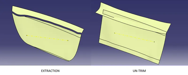
To create the part body we have to have another surface which is ectracted from class A surfce and untrimmed it.
Then extrapolated the faces needed and Offset it by the part thickness of 2.5mm and trim them to gether will get the basic B surface.
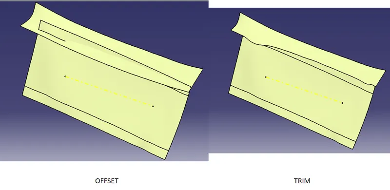
With the proper fillet values will get the final B surface.
C SURFACE:
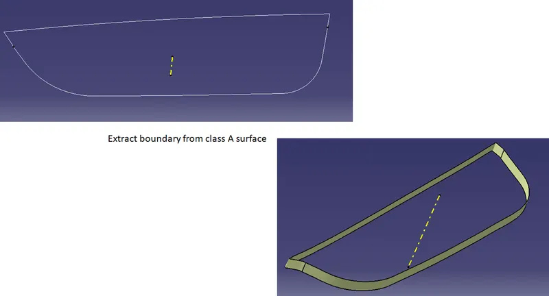
To complete the part surface creation we need to have C surface, from the class A bondacy we will be able to create with Sweep command.
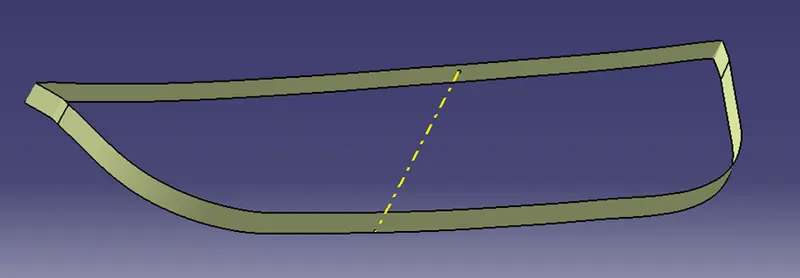
Will achieve the final C surfaec with minimal trim.
FINAL JOIN:
No we have all the surfaces so first wil Join Class A and C surface untill will get a single boundary.
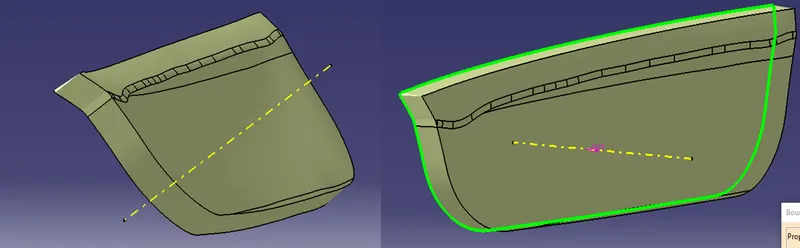
Then trim it with B surface for the final surface.
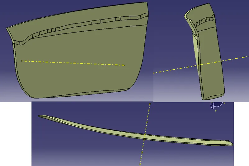
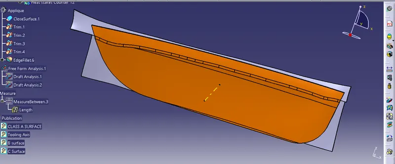
In the part Body make it will get the final Part Body.
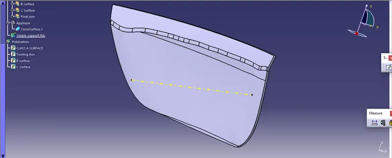
Performaed Draft analysis on the same.
B SIDE FRATURES:
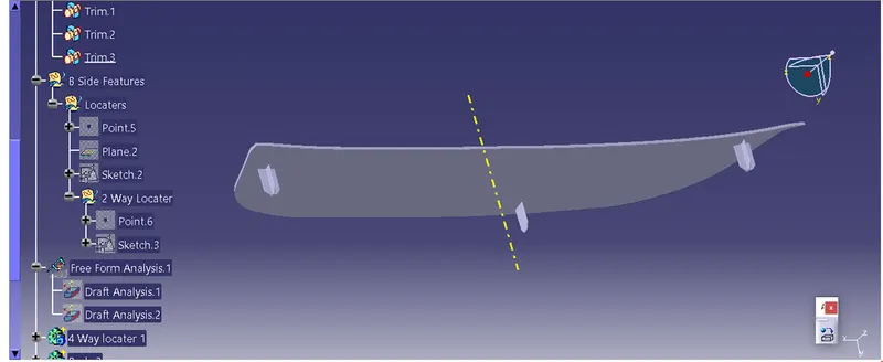
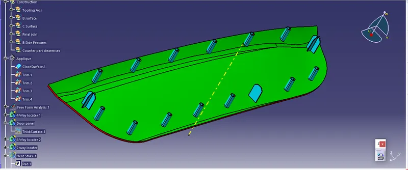
For the same component to fix on any of the Parent bod we need locaters. those locators and fixtures like Heat stakes are provided in this component.
First will create Locators with 3-2-1 principle. Arresting all DOF with all directions have only one DOF.
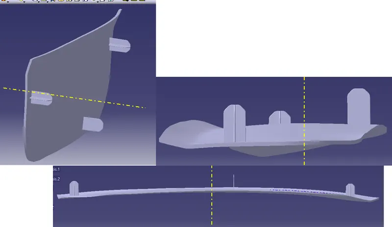
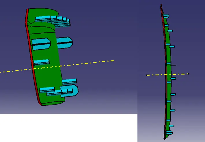
We have created two 4 way locater and one 2 way locater on the surface and fix them with the door Applique.
And we have considered all the design rules to create locaters.
So
locater wall thickness is 1.3mm
Draft angle is 0.5 degree
Fillet value 0.25mm
Entry chamfer value - 3 mm
The skecth is Positioned and Iso constraint.
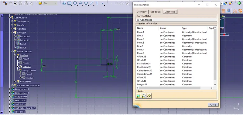
Different views of locaters
HEAT STRAKES:
Thre are the the one fo the fixtures to fix the child body to fix the parent body.
And these are also created with the same design rules attached them with the main body.
Here we have created one Heat streak and With the PARELLEL BOUBDERY option we are created the points on the line.to create the heat strakes.
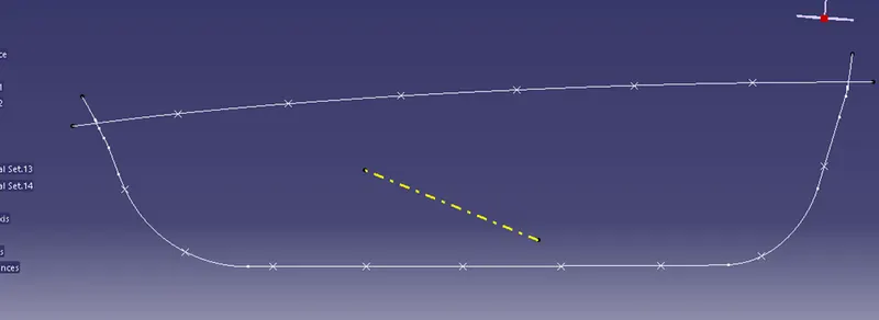
We have created one heat streak and copy paste special them and trensilated the, with Point-point command we have locate them with all the locations and union trimmed them with the main body.
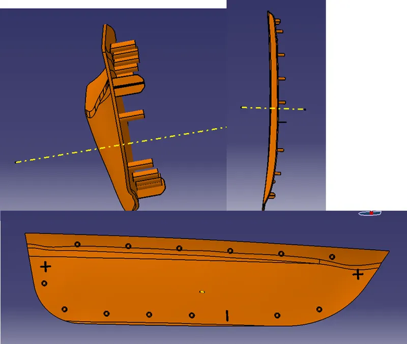
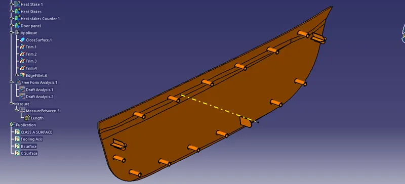
Again we have performed the draft analysis on it and following are the results.
Door panel Mounting Holes:
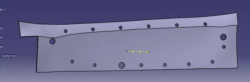
we have thickened the class A Surface by 2 mm .
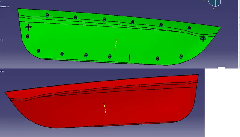
Most of the work is completed and these palne is then fixed to the parent body for that we gave to make slots in that.
By using the same sketches we have created the circular bodied and removed them from the door panel body.
For locaters the clearence between the surface and the edge would be 0.1 mm per side
And for heat strakes is 0.5 mm per side.
GEOMETRICAL SETS TREE STRUCTURE:
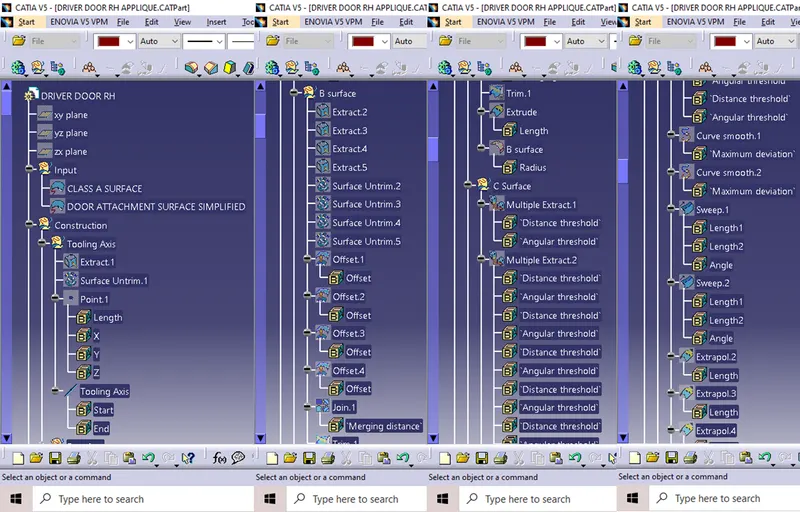
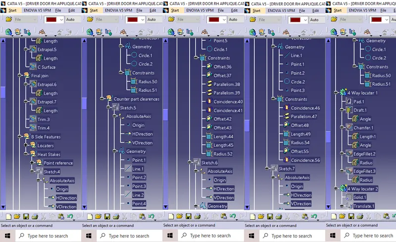
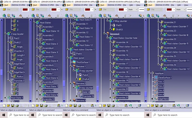
For performing the all tha above process we have followed the following process.
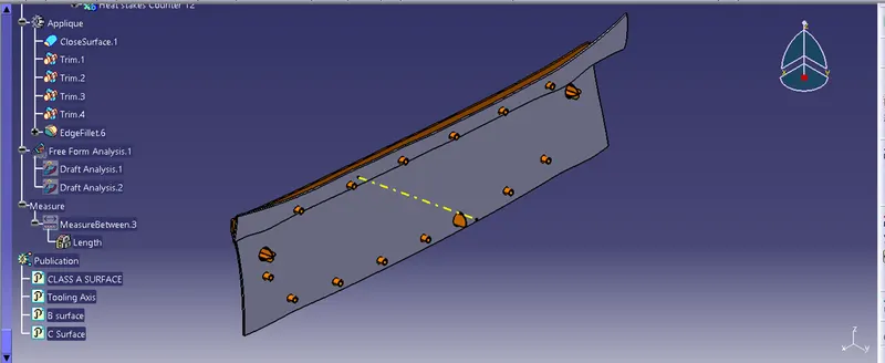
Final Body
CONCLUSION:
We have created the Solid part body from the Class A surface and attached all the engineering features to it. And performed Draft analysis on all instances.