Week 8 - Challenge 1 - Draft Analysis on a Fan Cover
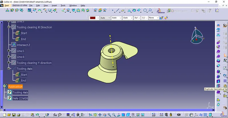
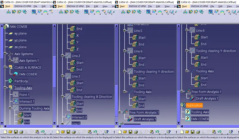
Geometrical Sets Tree structure
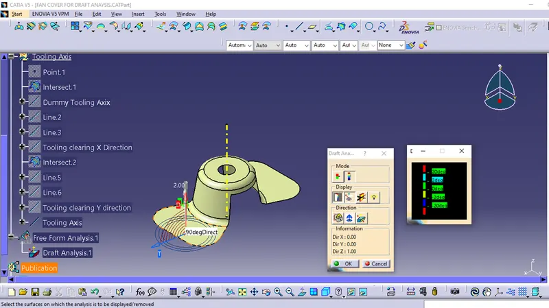
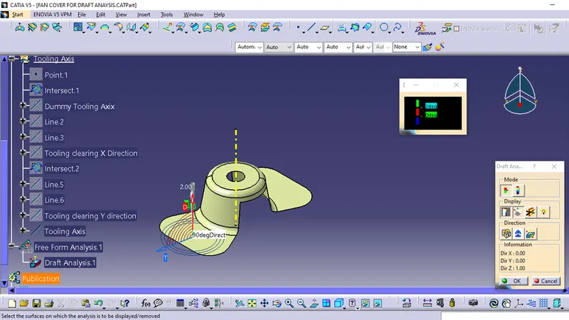
Draft analysis report
Fan Cover in different orientations
Isometric view
Front View
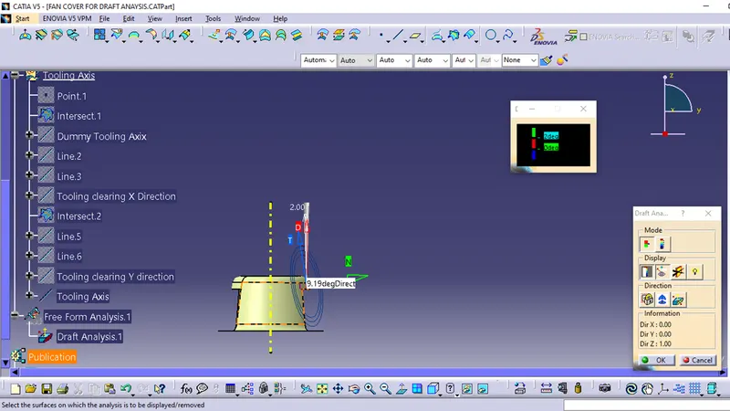
Top View
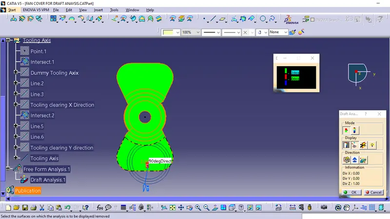
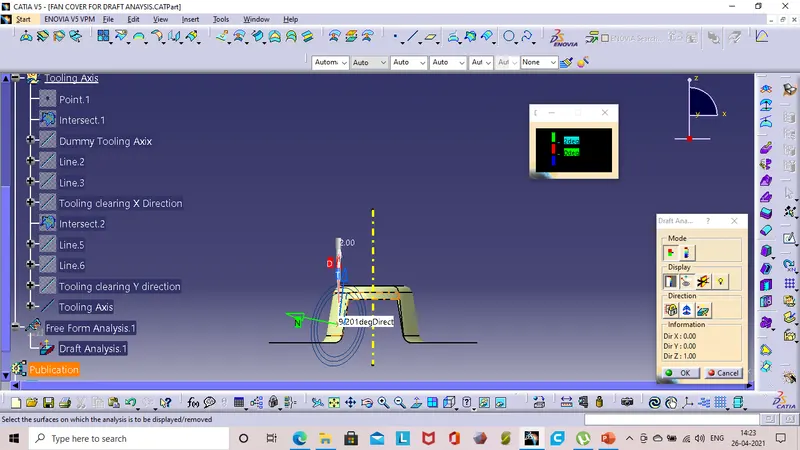
Side view
Report on draft ananlysis
This type of analysis is performed based on color ranges identifying zones on the analyzed element where the deviation from the draft direction at any point, corresponds to specified values.
Select a surface.
Click on the Draft analysis icon:
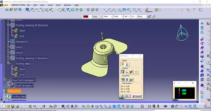
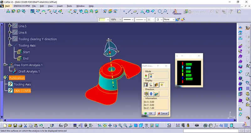
The Draft analysis dialog box is displayed. It gives information on the display (color scale), the draft direction and the direction values.
The Draft analysis Dialog box 1 dialog box showing the color scale and identifying the maximum and minimum values for the analysis is displayed too.
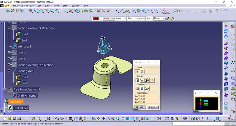
Double-click on the value in the color scale to display the value edition dialog box.
Enter a new value (negative values are allowed) to redefine the color scale, or use the slider to position the distance value within the allowed range, and click OK.
The value is then frozen, and displayed in a green rectangle.
The color scale settings (colors and graduated values) are saved when exiting the command, meaning the same settings will be applied when you will edit a draft analysis. New settings are created with each new draft analysis.
When the draft angle value of the surface is equal or smaller than a graduated value, the color below the graduated value is applied.
When the draft angle value of the surface is greater than the greatest graduated value, the color above this graduated value is applied.
Tooling axis Creation
Toolig axis is the direction in which the mold or core cavity opens.
Step 01:
Connectivity of class A surface
Checking the connectivity of class A surface,this can be done by creating the boundaries or by simply using the join option sucj that any openings can be easely visualized.
Step 02:
Analyse visuvally for the best tooling axis.
A dummy tooling axis will be directly created using a Point-Direction command.
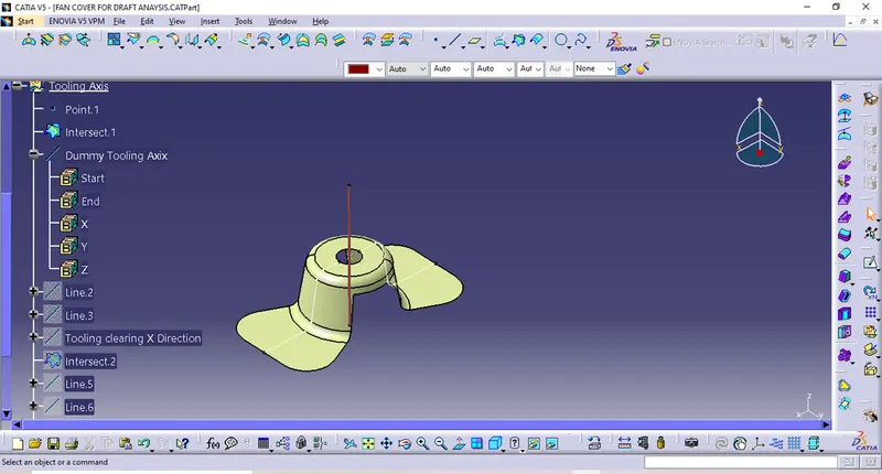
Checking the possibilities in all the directions of axis and find what are the probllems creation parts of the component.
The clearence checking alonng the axis direction will be done by creating an intersection along an axis on a plane with the model and constructing two lines contact with the walls, the lines bisecting
Creating intersection and Tooling axis for the checking along X-Axis
Uesing the intersection,lines will be created along the inclined walls these lines are used for creation of tooling axis by bisecting method where the two lones and point will be sellected as inputs.

Creating intersection and Tooling axis for the checking along Y-Axis
The above same process is carried to generate the tooling axix ont the Y axis.
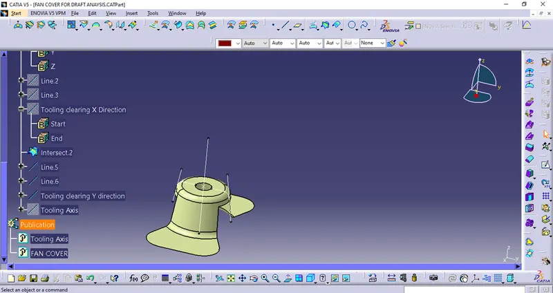
Tooling Axis creation:
Usinthe tooling axis created along X and Y axis, these tooling axes are used for creation of tooling axis by bisecting method where the two lines and point will be selected as inpots.
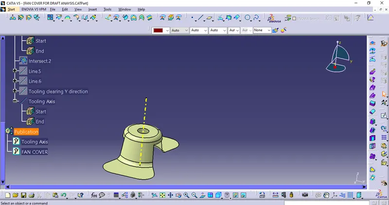
Publication :
Publication is used to make easely accessible of the published components.