Week 9 - Attachment Feature Creation - Challenge 2
OBJECTIVE:
We are going to create SCREW BOSS and DOG HOUSE on the given Coin holder and performing the draft analysis on the fianl body.
For the report purpse we are taking already created object whick is Coin holder which is made from the class A surface by performing all the operation on class A.
To do any operation on an any we perticularly need a Tooling axis whis major componenet of a part creation and tha same is useful while manufacturing.
First we need to slect the faces which are creatin problm, along those faces we have to create the dummy toolong axis on both the opposite faces.
Why because of those faces clear the tooling automatically remaining faces also cleared.
By BISECTING line of those two lines will be able to clear all the remaining all the faces thats why we always uyse Bisecting of the two lines create the Main tooling axis.
Some of the images are attaching for the referance to Create the tooling axis.
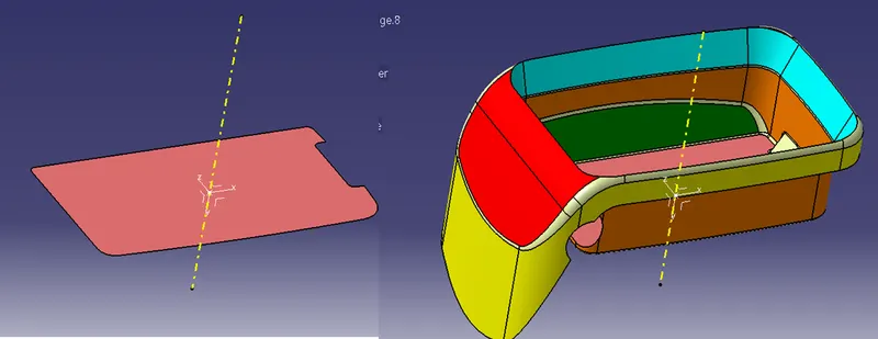
In this perticular case almose all the faces are poerpendicular each other so we have chose a linr Normal to the base line, which is our tooling axis.
DRAFT ANALYSIS:
Another most importent operation on the body, Once we create the tooling axis,along this tooling we perform the draft analysis, weather all the surfaces are clearing our tooling axix are not.
Each face is with diffeent colour which will be able to observe all the faces.
And son of the images attaches of the draft analysis.
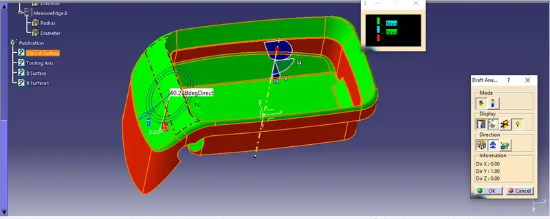
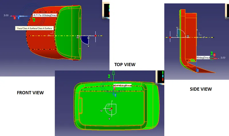
Next we are going to Create a solid part from the Class A surface along iwwth the tooling axis.
Class B Creation
From the class A Surfae we have to extract all the faces and untrim them, Extrapolated by some distance.
Then offset them by 2.5mm, trim them each other will give us the class B surface.
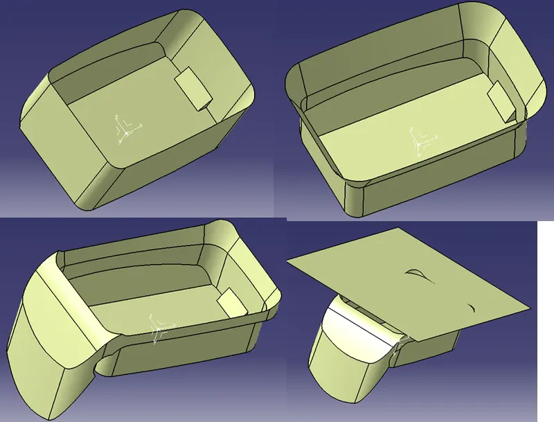
With proper fillet values will get the final Class B surface.
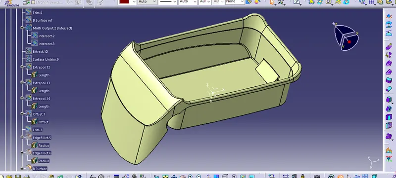
Class C surface:
Then from the class A surface boundary will be able to sweep the Class Surface along with the siurface.
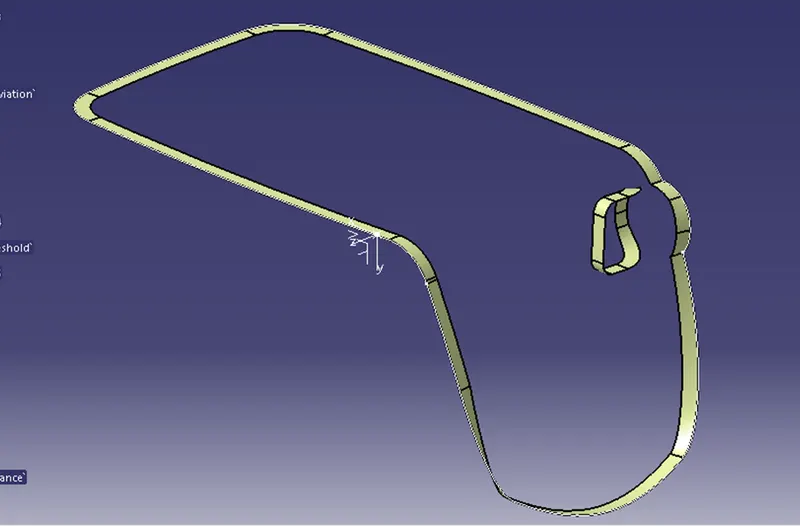
First we trim class c surface with B Surface and Jin them with classs A surface
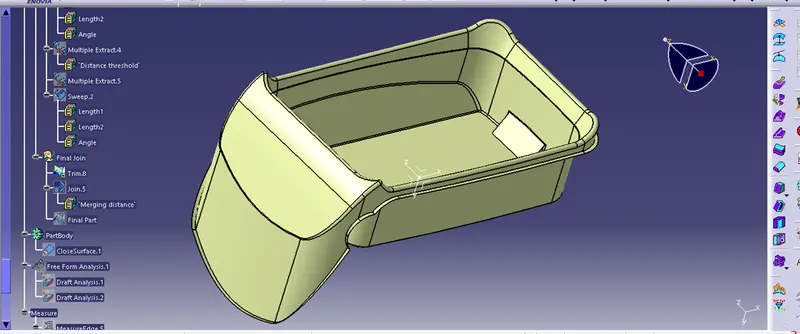
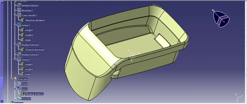
From the part body we make it as a solid.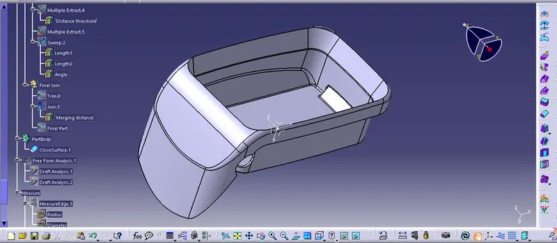
For the previous we challange we have created the ribs and tha same file is used to create SCREW BOSS and DOG HOUSE.
SCREW BOSS:
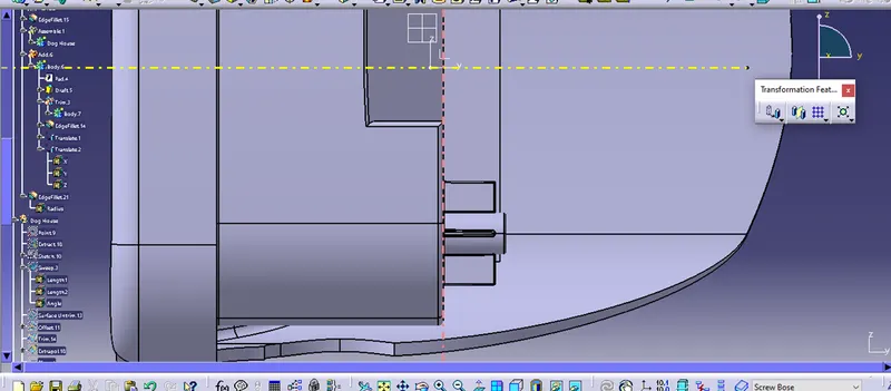
From the Solid Body we have extraces a base durface and we have created two circles and pad them with 12mm, and drafted them with 0.5 degree angle.
And for support we have creates four ribs following all the design rules.
All the operation performes in Positined sketch and Completly iso-constriainted.
We have Uninon tirmmed both tibd and Pad.
Attached it with main Body.
Fillet value 0.25 mm
DOG HOUSE:
On the other corner We have extracted the Base Surface from the Class A surface.Ofset it by 2.5mm, on the surface as reerence we have created a rectangle.
Sweep it by 25 mm along the tooling axis with the minimum draft 1.5 degree.
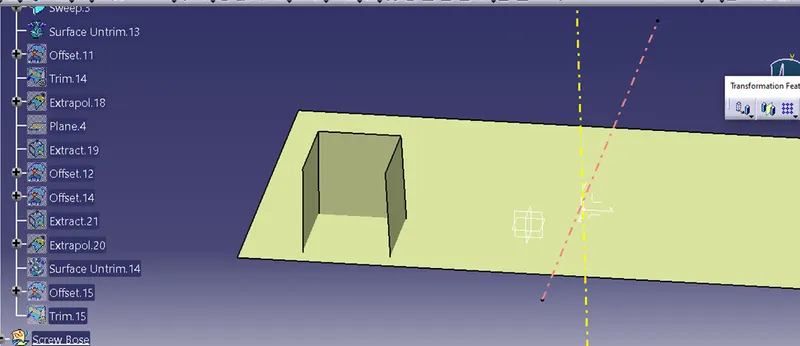
The base surface is ofsetted agin with 20 mm and tim it with The Skecth sweep.
Then make as solid With the thickness value 2 mm.
In the same way for hte base slot also we have extracted the base surface and ofsetted with 4 mm as the base of the dog house is to lie between 3 to 6 mm.
And with split command we have remove the base marial.
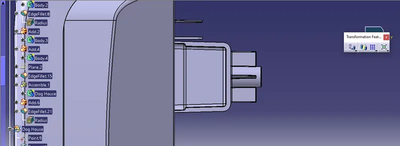
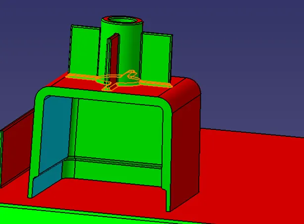
This Dog house will not clear in the main tooling axis, for this we have to create another tooling axis along the Z direction that is side core tooling axis.
We do perfirmed the Draft alalysis along with Side core tooling axis.
From the previous Screw Boss we have copied and paste special,
Placed it on the dog house with Shift with coordinates.
Then the final Join is taken place.
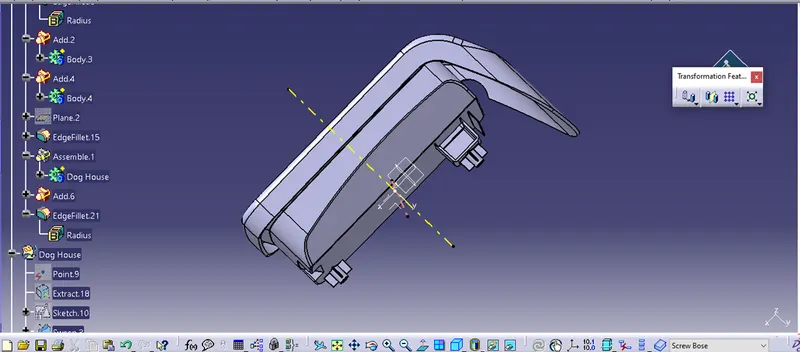
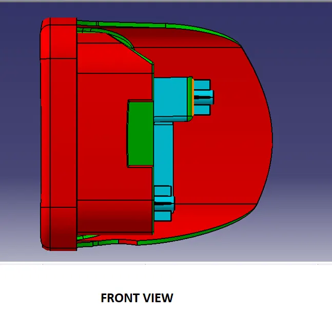
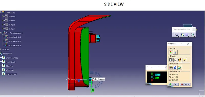
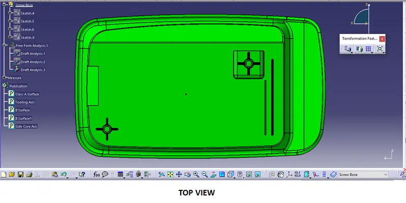
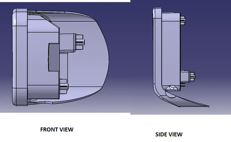
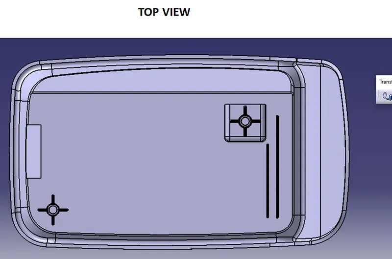
Final Part Body in different views
Draft analysis on Final Body
We have performed the Draft analysis seperatly for dog house as it has a side core tooling axis.
FInal Body along with tooling axis.
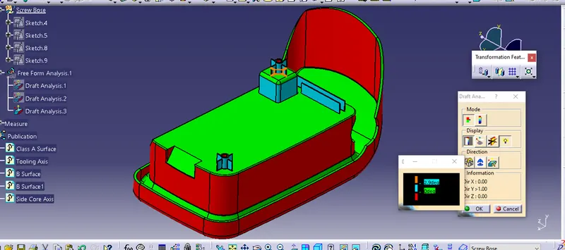
Different views