Fender Design Challenge
FENDER:
Fender is the American English term for the part of an automobile, motorcycle or other vehiclle body that frames a wheel well (the fender underside). Its primary purpose is to prevent sand, mud, rocks, liquids, and other road spray from being thrown into the air by the rotating tire. Fenders are typically rigid and can be damaged by contact with the road surface.
Sticky materials, such as mud, may adhere to the smooth outer tire surface, while smooth loose objects, such as stones, can become temporarily embedded in the tread grooves as the tire rolls over the ground. These materials can be ejected from the surface of the tire at high velocity as the tire imparts kinetic energy to the attached objects. For a vehicle moving forward, the top of the tire is rotating upward and forward, and can throw objects into the air at other vehicles or pedestrians in front of the vehicle.
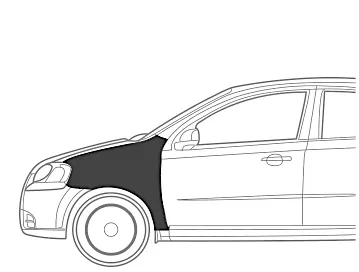
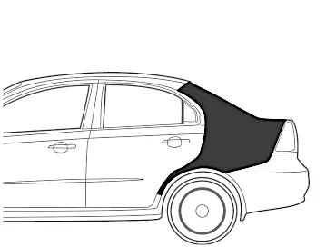
Among all it is a side matal sheet which keeps clean, and protect the vital componenets from the collision. And it defines the car style and helps to improve the aerodynamic of the vehicle.
Steel is more predomenatly is used to manufacture in most of the case as the cost of hte car increases it will be made aluminum and carbon fiber.
There are two types of fenders,
1. Full bumper type
2. Half bumper type
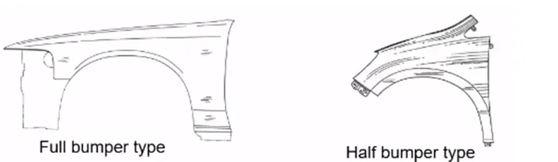
In order to reduce the cost and to improve the vehicle perfirmance only Half bumper type fenders are in live now.
So from the given data we are going to create the following mountng locations.
Drip area
Bumper mounting area
Sill mounting area
A piller mounting area
Wheer arch mountings
We have completed some basics about fender, now we get into the actual degign.
The following is the given data for the fender design.
Master section
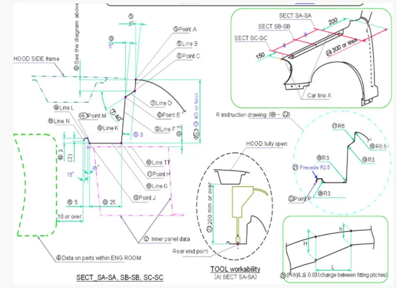
Given Fender skin for the design in cad.
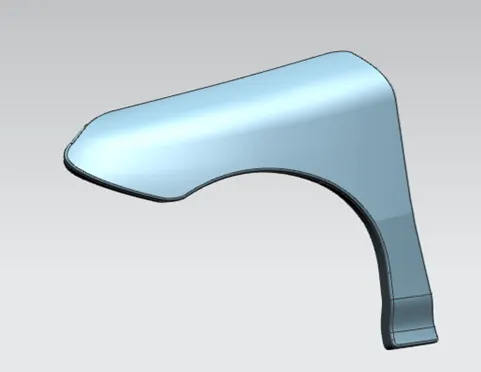
Now on the basis of Master section we will start creating the drip area, according to the given dimentions will start creating it.
For the basic use we will offset the outer most curve of fender by 9 mm
And with the law of extention option will start creating teh surface along the vectors.
And created curve on surface in different areas where we need the smooth surface for our mountings.
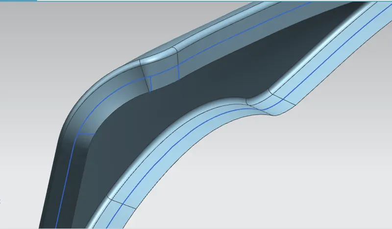
Will use the commands like curve on surface, trim sheet and Law of extension untill we get the proper surface for out mountings.will repeat for all the mountings.
Then here we need to consider one importent thing about the Drip area mounting which is 300 mm or less form the rearend, and 150 mm from front end and it should not touch the enhine area.
For this to get the exact loaction we have created the datum planes and get it intersected with the surface to get the exace location.
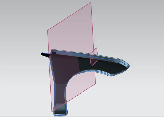
Then from the intersection line with law of extension command we created the drip area.
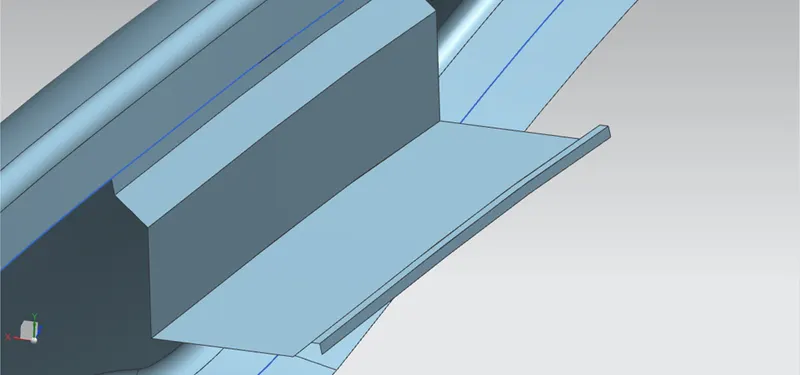
Before the blend we have provided the Dart to give the strength to the body.
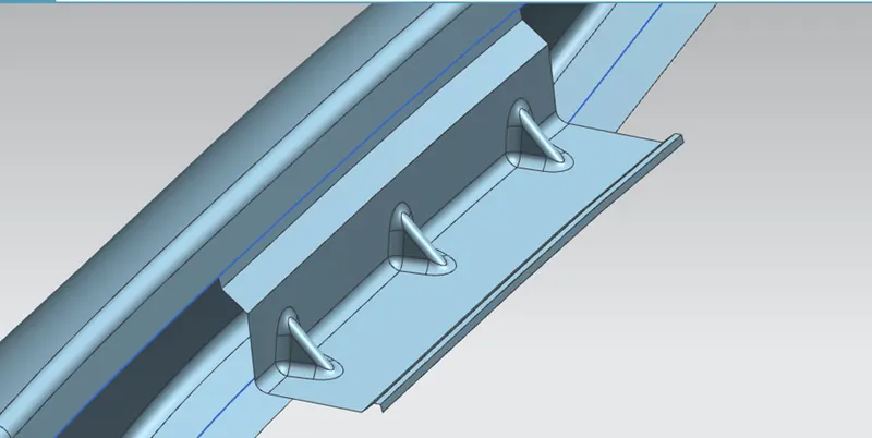
With all the blends will finish the creation of Drip area.
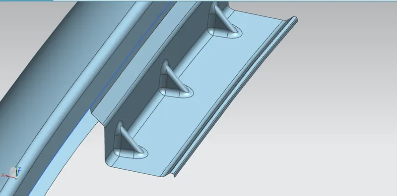
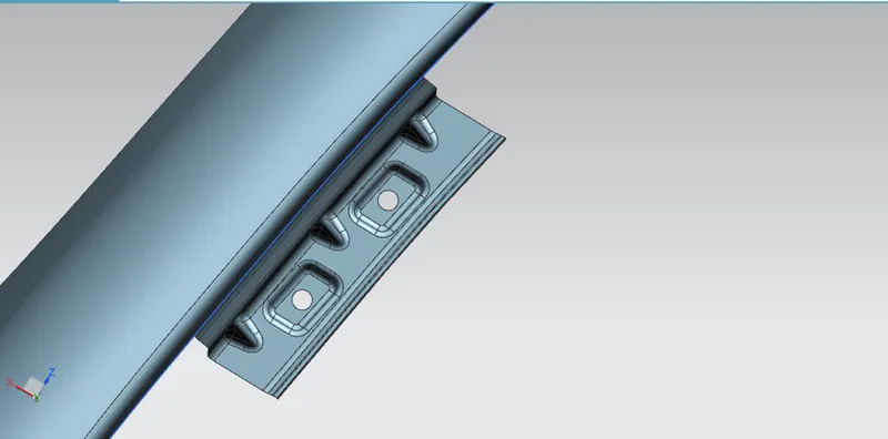
All the surfaces are created according to the given master section.
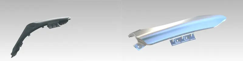
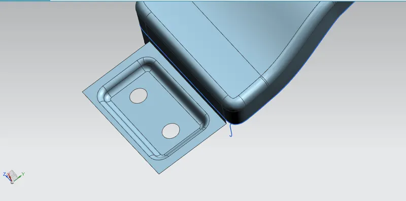
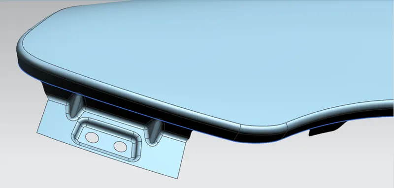
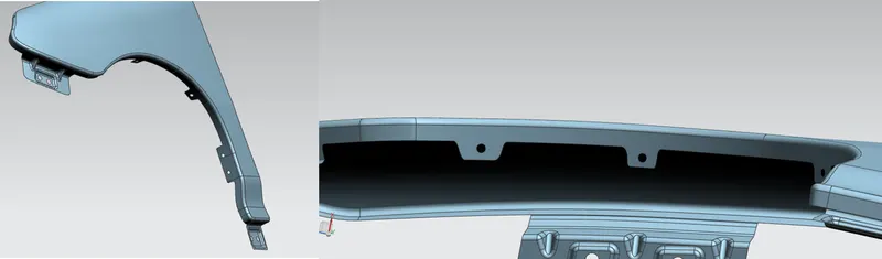
in the same way will do create the munting at sill, bumper area and the A piller area. following images are shown after all the blends.
Sill area
Front bumper area
A piller area
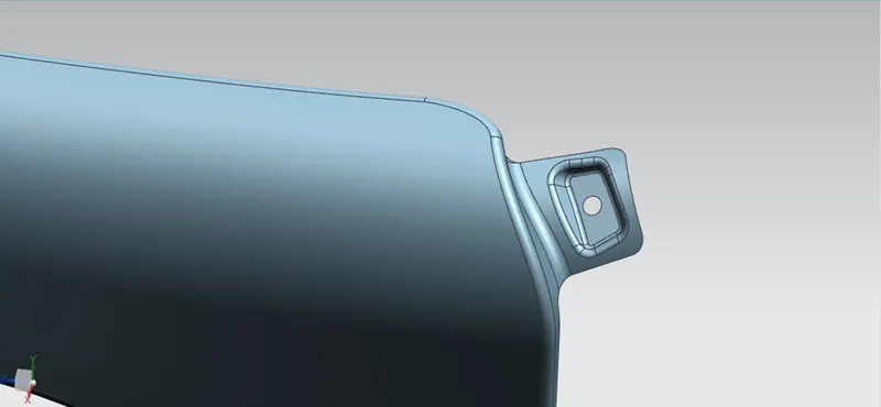
Mountings at wheel arch area
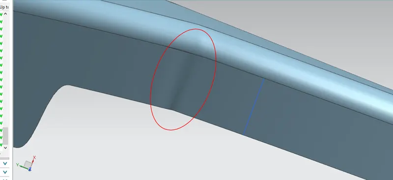
Before thickining I have face an issue becuse of the inappropriate surfae which is resolved by removing it and generated a new sheet with through surve mesh.
Before
After
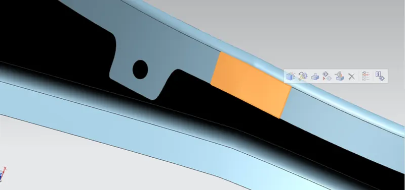
After this we will find the critical areas and make them smooth will give us the final part body.
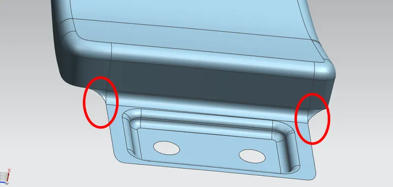
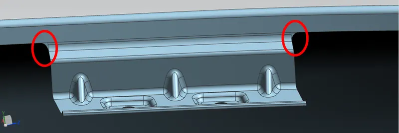
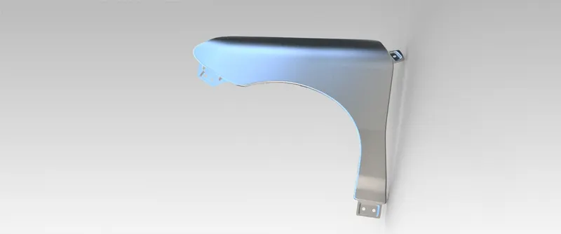
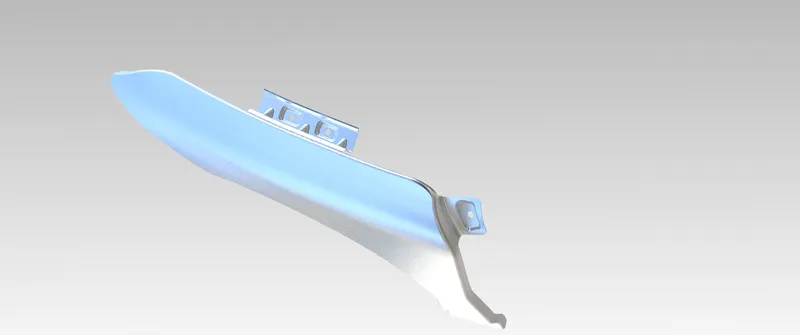
This completes the designing of fender with all the mountings.
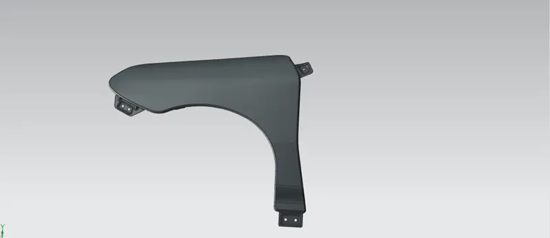
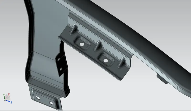
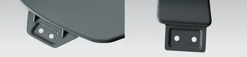
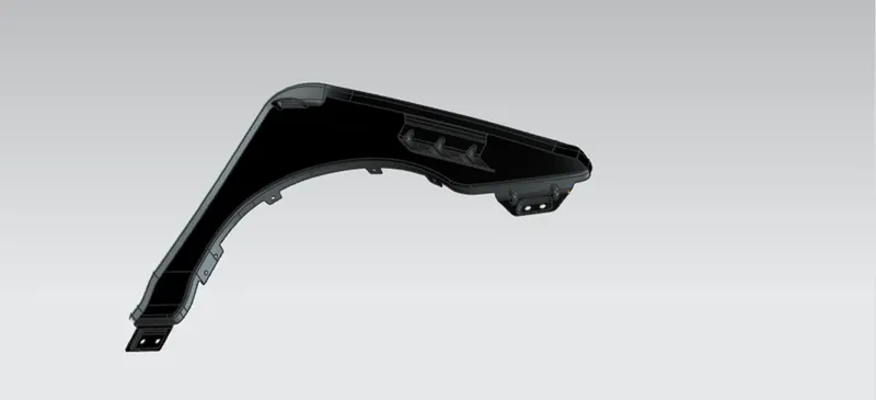
Following are the some rendering images of the model.