Week 11 - Final project
AIM:
Our main aim is to generate a side door panel From the given class A surface with all B side features ( For mounting Doghouse and push pin; For joining of parts Heatstakes ), and performing The draft analysis on each part.
GIVEN CLASS A SURFACE
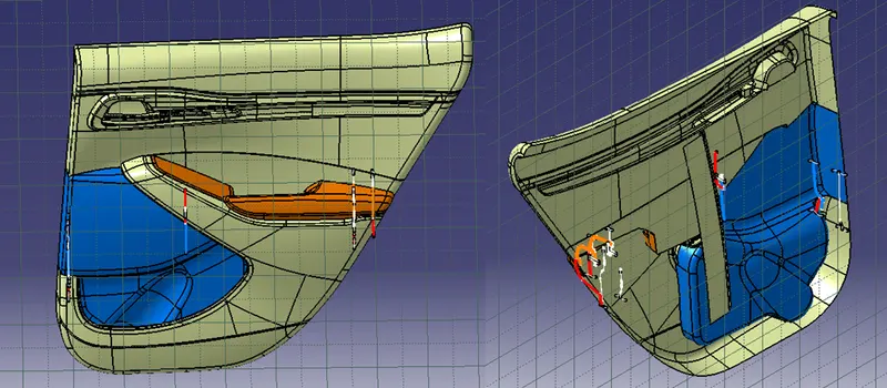
For the part generation i have followed the folowing process.
1. Check the class A surface if it is not proper let it correcte.
2. Tooling axis creation
3. Draft analyisis
4. B surface Creation
5. C surface creation
6.FInal plastic body creation
7. B side Fratures
STEP 1: Check the class A surface if it is not proper let it correcte.
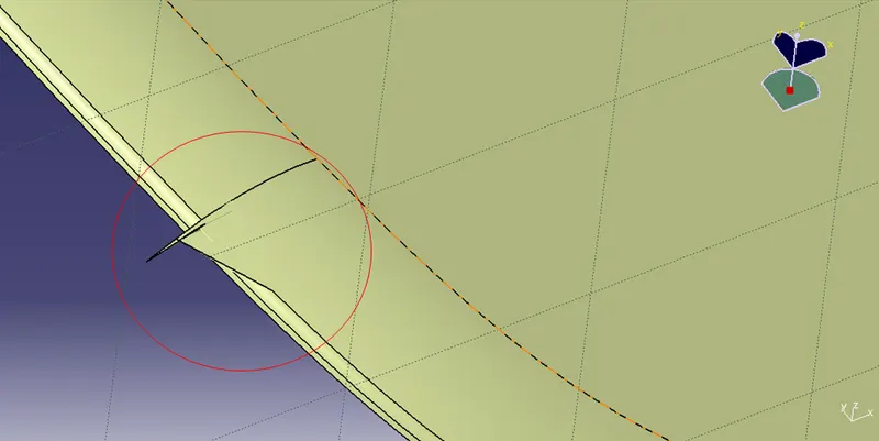
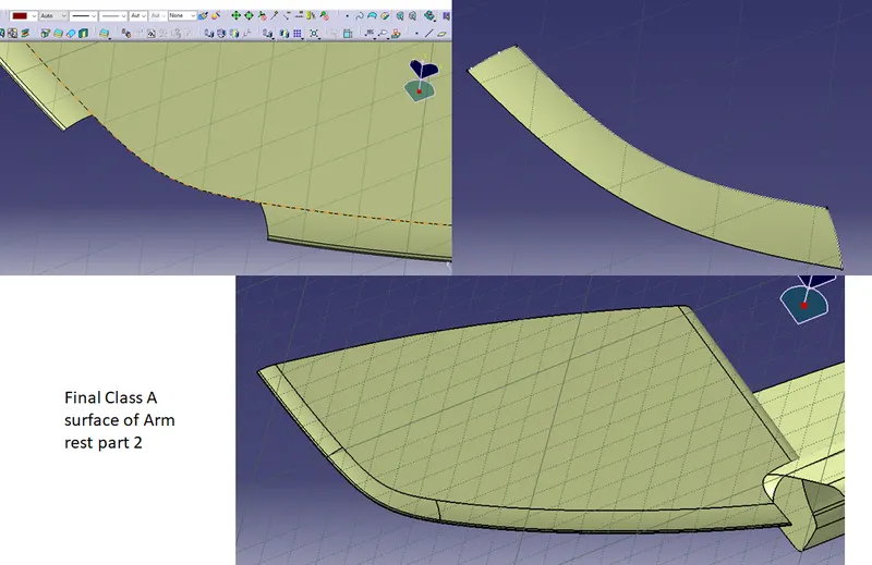
From the class surface all the surface are clear except the Arm rest part 2.
It has som bundary problem that is to be cleared. First i have removed the surafce which are not proper and by extracting the boundaries i have created a new surface and joined them together.
STEP 2: Tooling axis creation
This is the main tooing axis with which our core and cavity will act along with it.This will be created in many ways, but mostly we prefer to create along on out any of X,Y and Z axis which are simple and easy to create.
In this model we have created the Tooling axis mostly perpendicular to the surface and some are generated through the bisecting method. All the images are attached below and the tooling axis of each part.
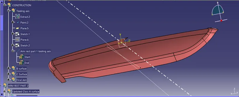
ARM REST PART 1
This tooling axis is created with the bisecting method and the bisecting line is with two opposite sirface intersection line.
ARM REST PART 2:
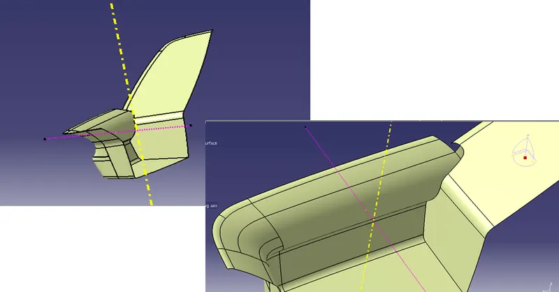
This tooling axis isis perpendiculat to the nase surface, as it has the intricate shapes which leads us to creation of side core axis.
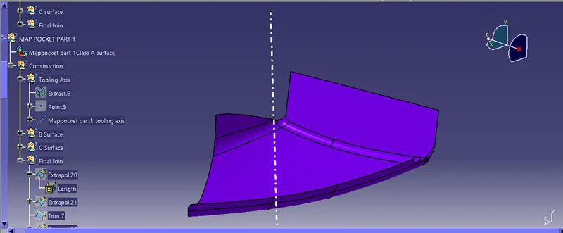
MAP POCKET PART 1:
Even this is a simple surface we have considered the line perpendicular to the surface.
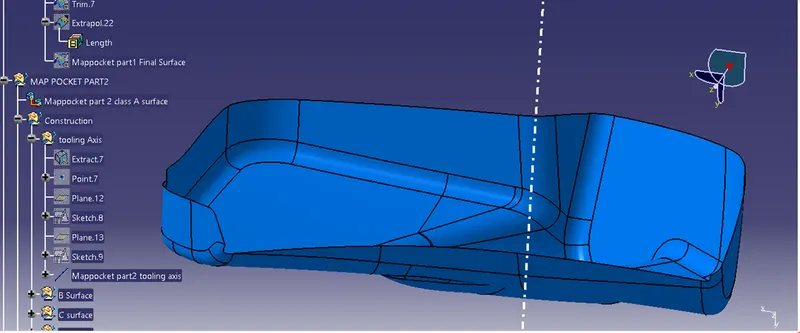
MAP POCKET PART 2:
This is genetated througn bisecting metod.
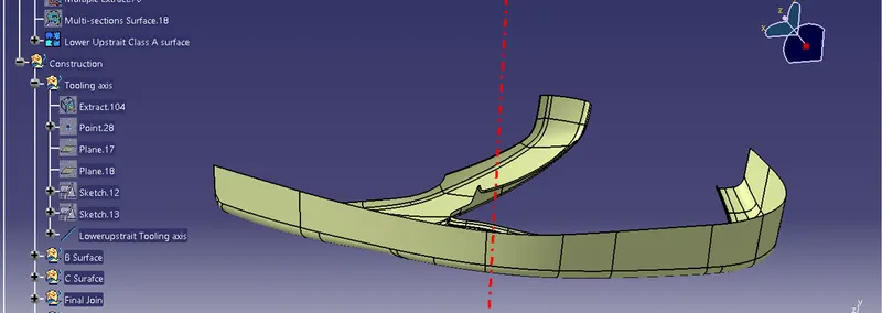
LOWER UPSTRAIT :
In this i have extracted a surface with thaat plane a line is drawn normal to it, which is our tooling axis.
STEP 3: Draft analyisis
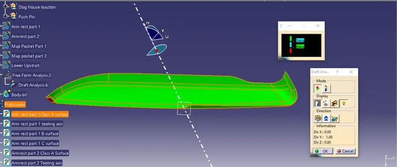
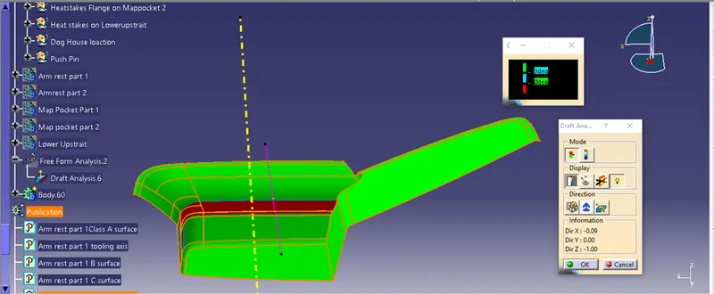
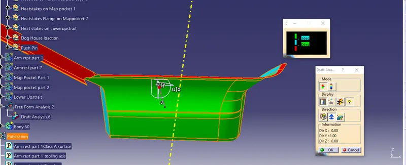
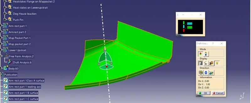
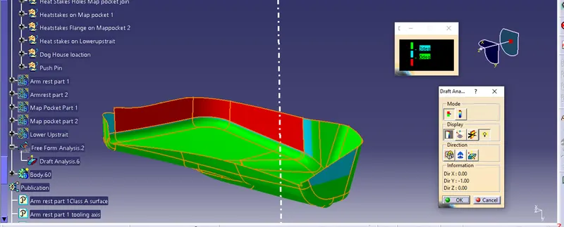
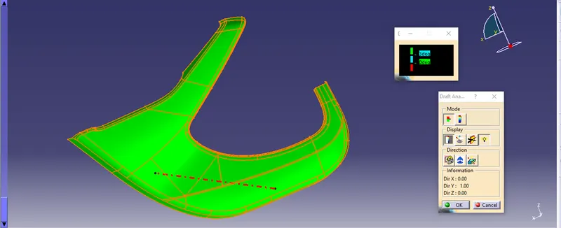
So now we have the tooling axis of all the sirfaces, will start the draft analysis on each surace with the minimum draft angle as 3 degree and the colours are given as follow.
Green - More than 3 degrees.
Blue - 0 to 3 degrees
Red - Less than 0 degree.
As this is tha basic class A surface it has some ares are not falling under our draft abalysis and all of those are showned below.
ARM REST PART 1
ARM REST PART 2
MAP POCKET PART 1
MAP POCKET PART 2
LOWER UPSTRAIT:
STEP 4 :B surface Creation
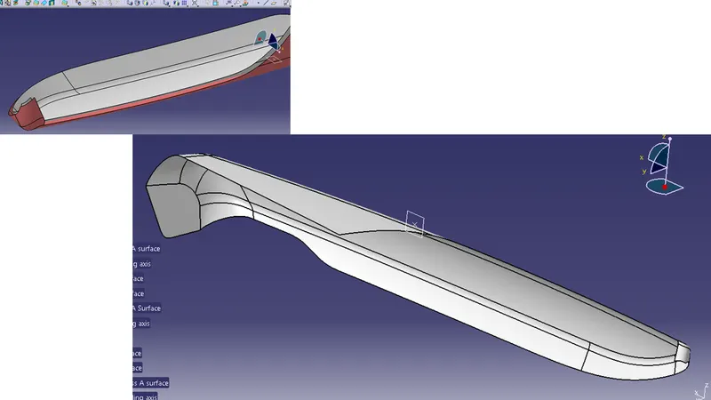
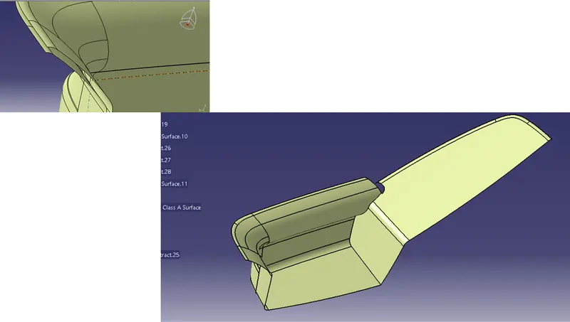
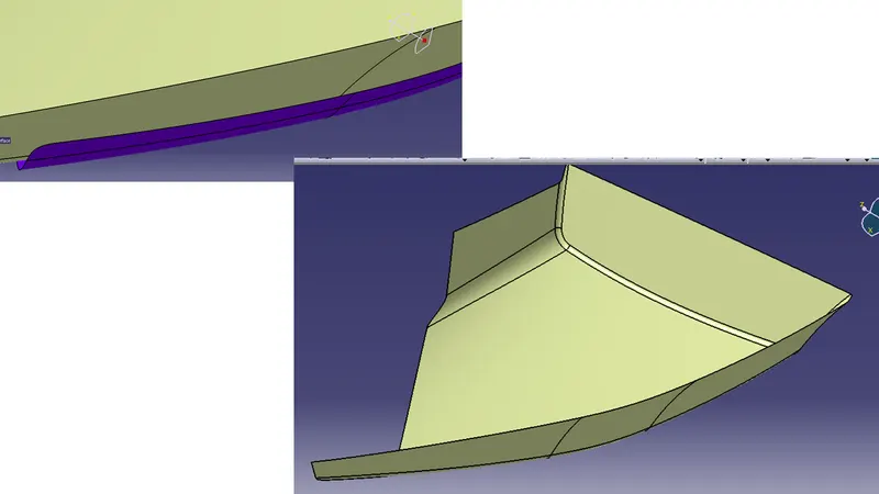
The next step is to create the B surface Fromm the class A surface, as the surface give is a basic class A Surface from the individual surfaces extration method is not giving the proper results, so i have off set the class A surface by 2.5 mm ( part thickness is 2.5 mm from the sections). So that is our final B surface. The same is followed for all the surfaces.
ARM REST PART 1
ARM REST PART 2
This perticular surface be able to off set niut some edges are unable to offset, so i have uses the sweep option to create another surfase and the same is joined to the main b surface.
MAP POCKET PART 1
This is created through our regular method offset the nade srface anf extapo;ated and trimed them to get the final B surface.
MAP POCKET PART 2
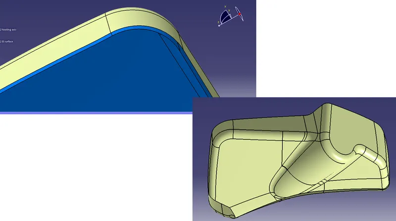
LOWER UPSTRAIT:
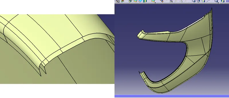
STEP 5: C surface creation
So We have both class A and b surface woth both of them will be able to create c surface by Sweep method or wth Blend method.
ARM REST PART 1
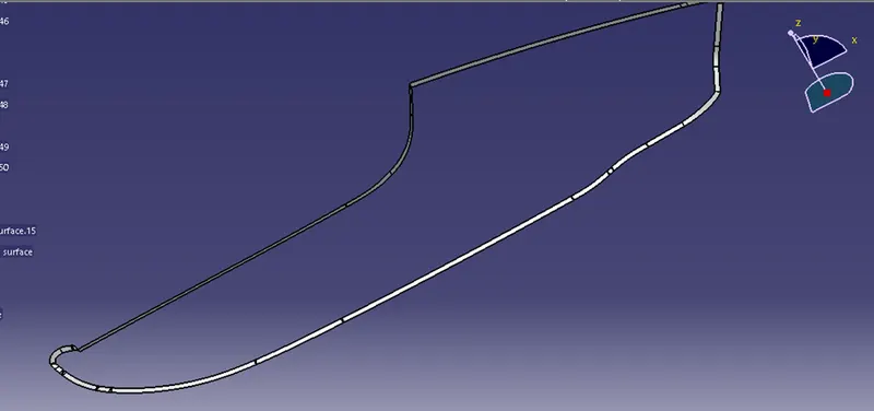
ARM REST PART 2
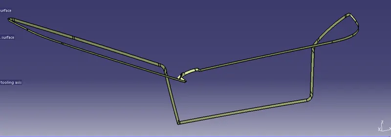
MAP POCKET PART 1
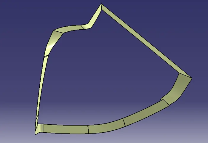
MAP POCKET PART 2
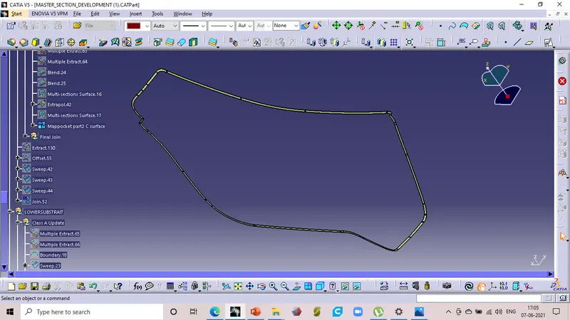
LOWER UPSTRAIT:
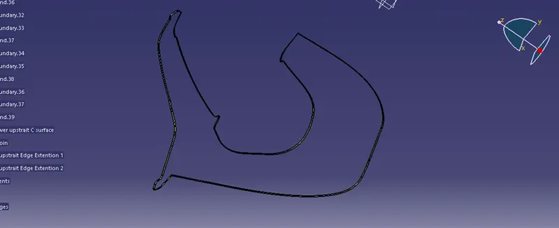
STEP 6 :FInal plastic body creation
Now with the join command will join all the surfaces by checking the boundary command, if it is not failing so it required the some corrections, after all the corrections will get the final sirface.
In the part work bench will make the surface as a solid bodies.
ARM REST PART 1
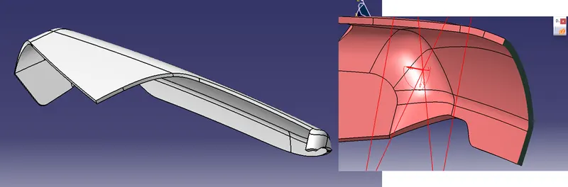
ARM REST PART 2
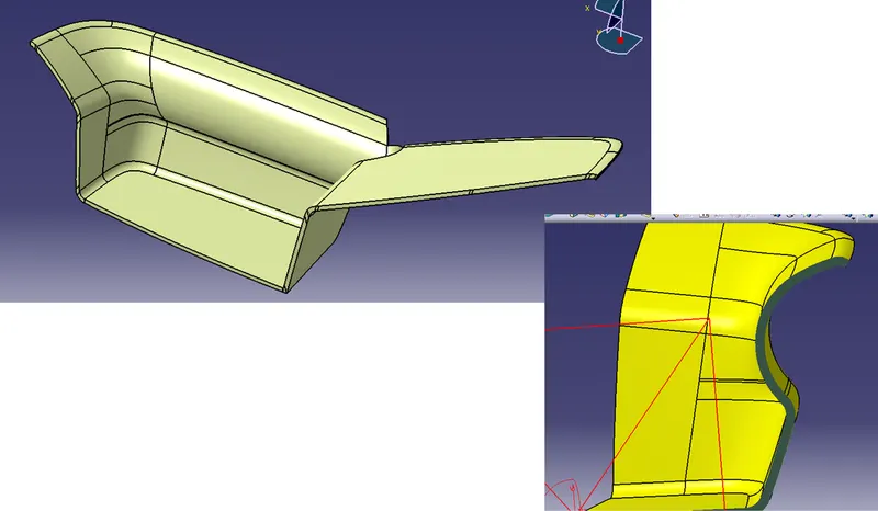
MAP POCKET PART 1
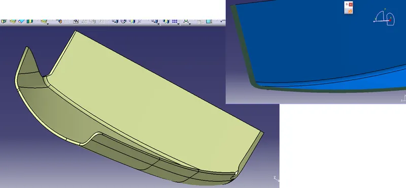
MAP POCKET PART 2
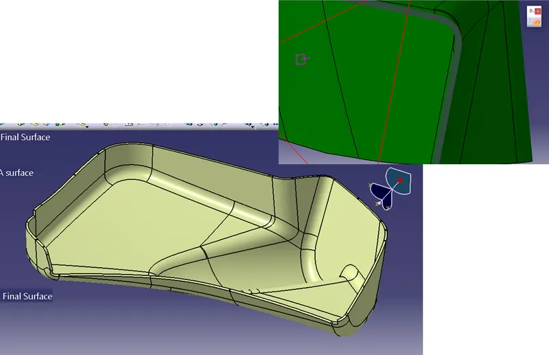
LOWER UPSTRAIT
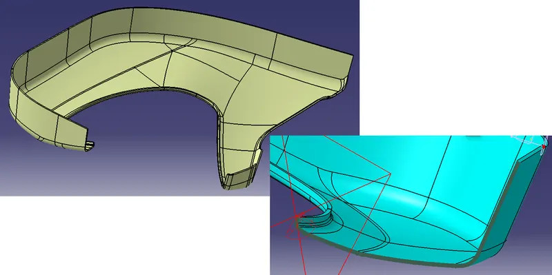
STEP 7: B side Fratures
Once we have all thepart bodies to make it a final produce we need them to fix eaxh other with the help of heat stakes and Dog house.
To create all the Side fratures involve the flanges to fix each other, from the master section we have extracted lines and creates the flanges, with the boolen operations i have joined them together.
I have followed all the design rules to create a Rib and Heat stake
All the flanges and heat stakes after joining the mail body is shown below.
Arm rest part 1
Foe the Arm rest part 1 we have created a flange which rests on Lowerupstrait heat stakes to fix and Heat stake for it to attach on the other body.
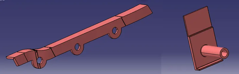
Final Door arm rest part 1
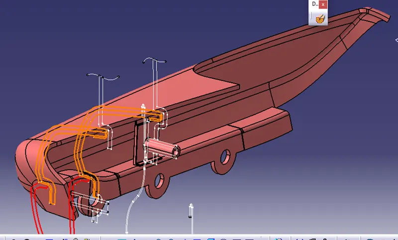
Arm rest part 2
Arm rest part 2 only have 3 heat stakes.
The same heat stake is copied and transilates with Point to point command.
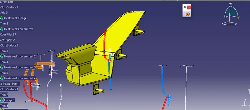
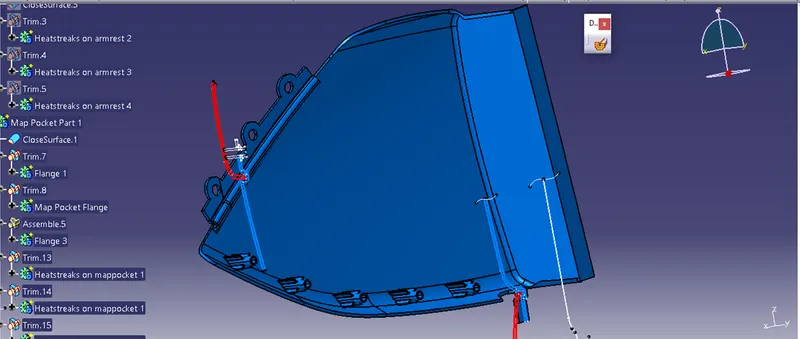
Map pocket part 1
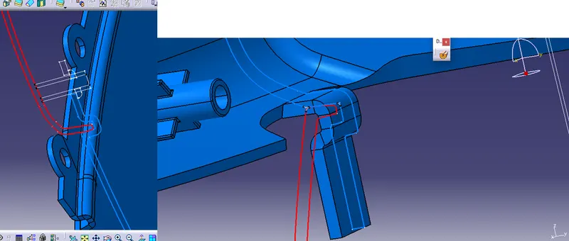
Here we have added an extra flange where it is in touch with sheet metal body.
Map pocket part 2
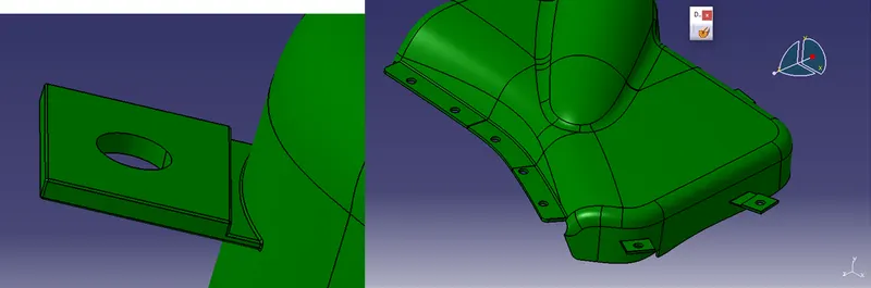
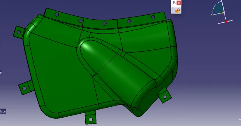
This part have only flanges.
One flange at the connection two map pockets and small flanges around the Map pocket part 2 where it rests on the lower substrait.
Final map pocket Part 2
Lowerupstrait:
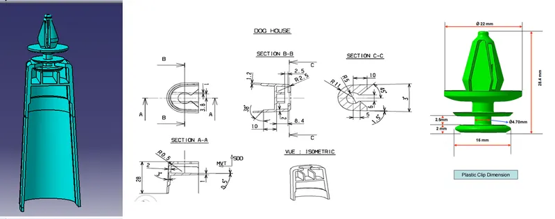
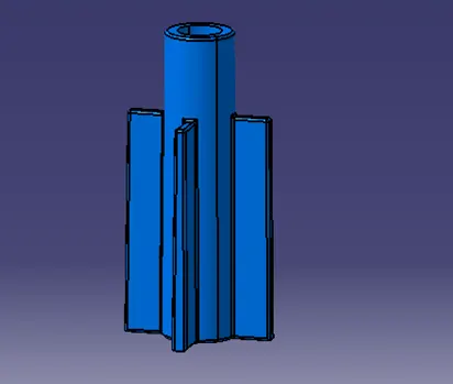
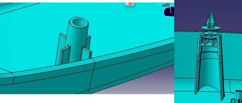
This is the main part to hold all the other Sub elements so it requires a Dog house to hold on and the Final Dog house is also shown below and is created by both surface and part workbench.
This is locates 25 mm from the side walls of lower upstrait.
In line with the side wall top surface and dog house top surface.
A push button in is given that enables to fix easy ti the sheet metal surface.
And heat stakes are transialted through the same point to point command,
Final Lower upstrait
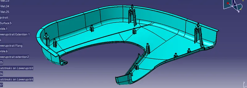
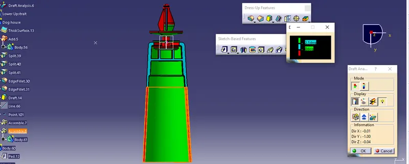
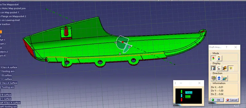
After creation all the part bodies and b side featires we haave performed the draft analysis on them, and the resunts are shown below.
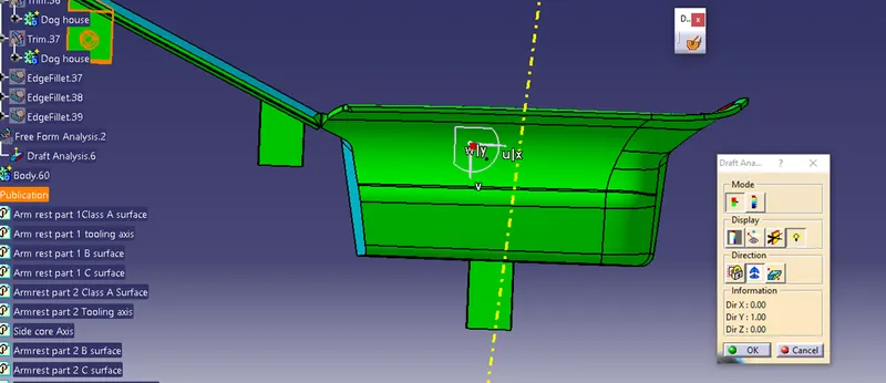
Dog House :
As it has the side core analysis is performed along it first and them throuth the main tooling axis.
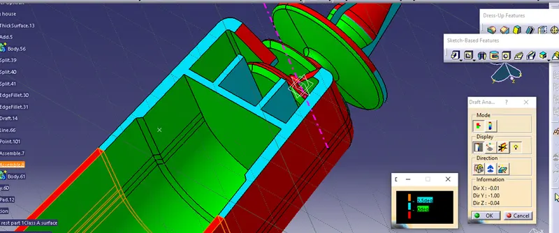
Arm rest psrt 1'
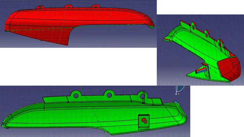
Afrmrest part 2:
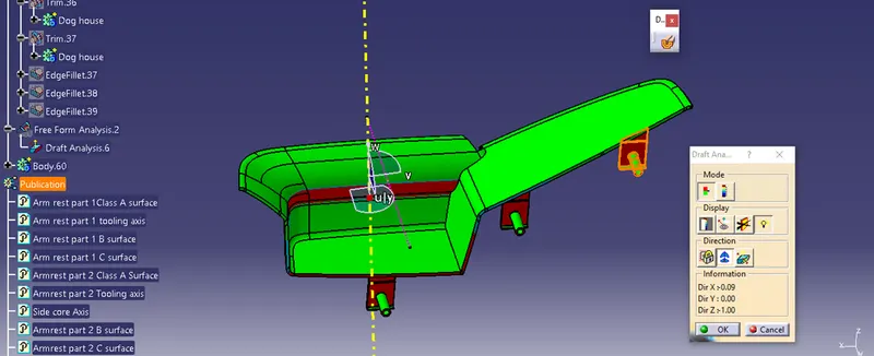
From side core Axis
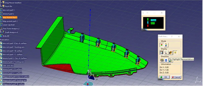
Map pocket part 1
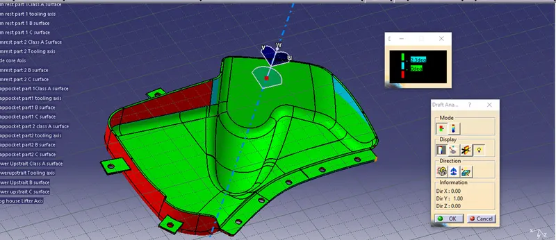
Map pocket part 2
Lower upstrait
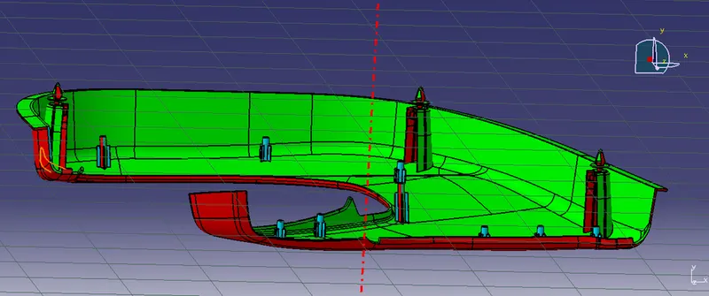
With this we have completed the Final body with all the engineering features following all the design rules.
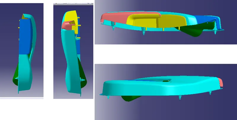
Final part in different views.
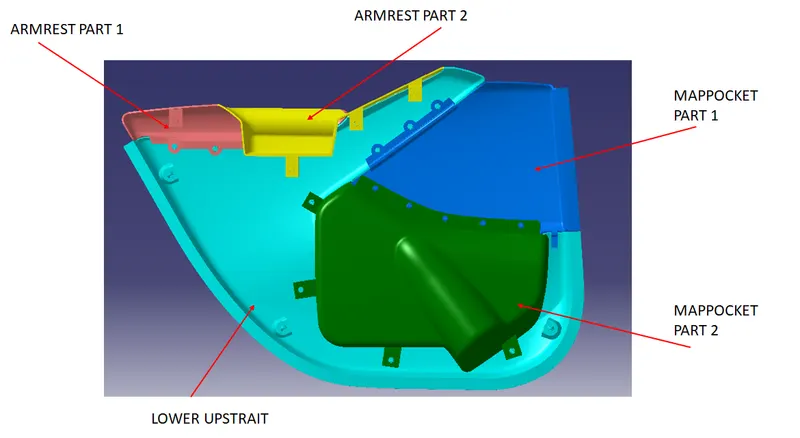
Iso metric View :
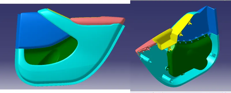
Other Views:
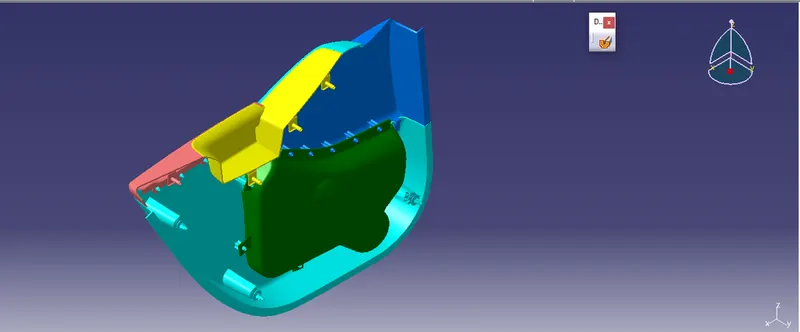
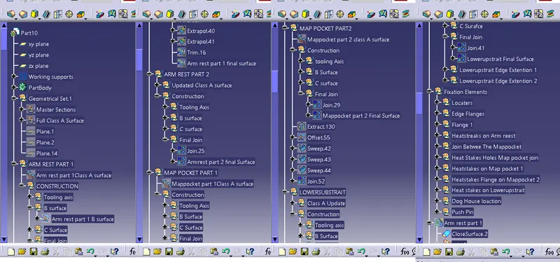
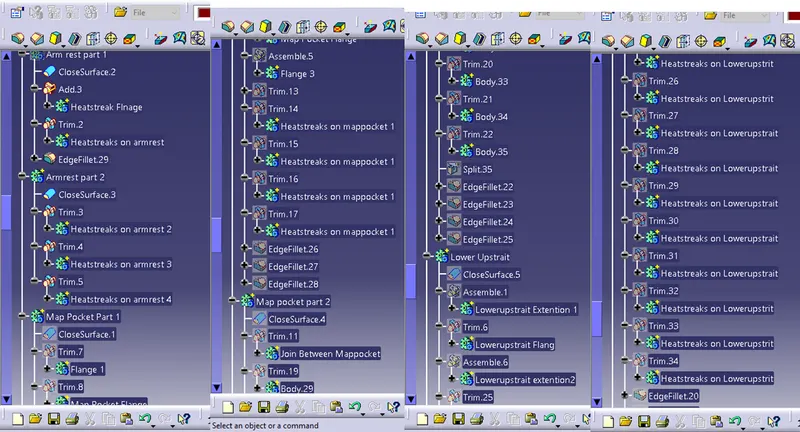
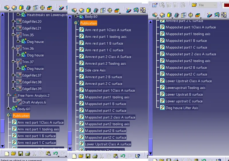
A brief Geometrical sets tree structure and all the sketches are fully constrained.