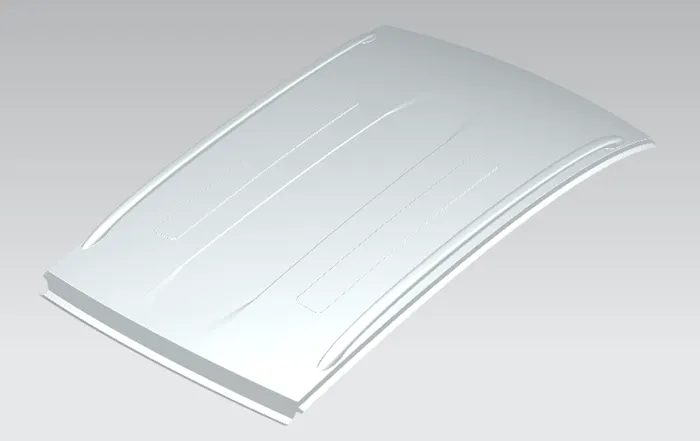
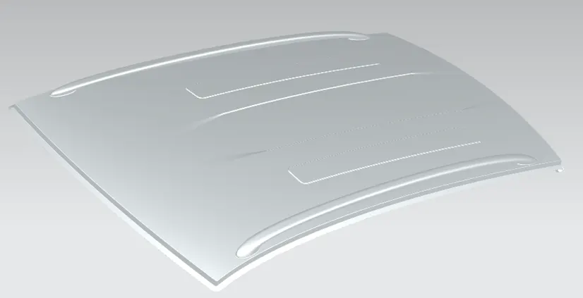
Roof challenge
OBJECTIVE:
Our objective is to create the proper reinforcements in proper locations of the roof as it should with stand the basic amounts of Heat distortion criteria and Snow load condition.
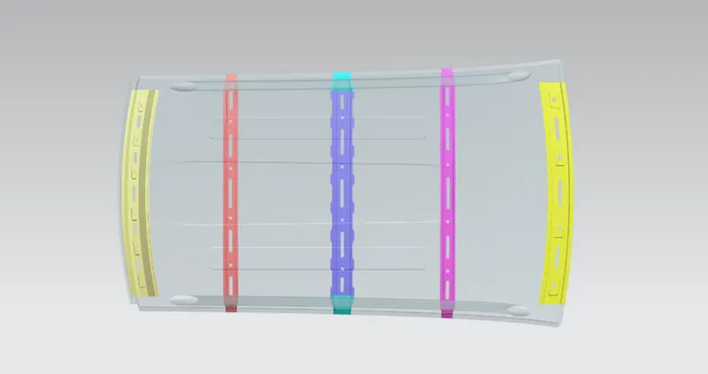
Ths whole process involve the following steps to create the proper reinforcement.
- Creation of all the supports Front roof rail, front and rear bow roof rails, center roof rail, rear roof rail according to the goven master setion.
- Here I have added some styling to the roof.
- Final joining and thickning.
- Draft analysis
- Load calculations
REINFORCEMENT CREATION :
In this perticualr given class A surface with a visual condition we have decided to give two bow roof rails with reinforced center roof rail.
As all our outer surfaces are symetrical we have extracted the outer surface and working one half of it and another half will be mirred to get the full part.
This is created from the given master section, and the process is given below.
From the given we have forst created the flange al around the roof with the given angles with law of extension command.
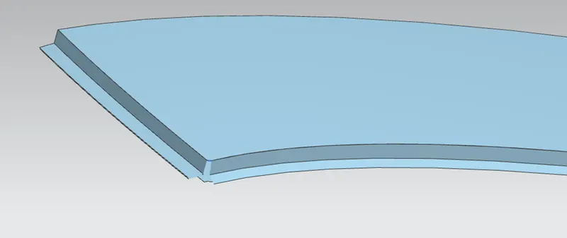
Rear roof outer rail:
Same like front flange we have to create the rear flange as it is not so simple as the front, in consideration with the master section we have created the rear roof panel also.
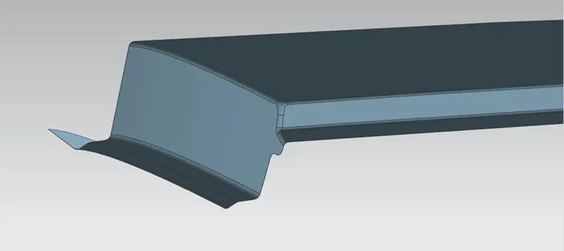
Here we have used a new commnad Blend corners, for the three corners to make smooth.
Rear roof outer rail:
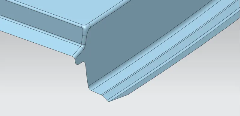
Same like front flange we have to create the rear flange as it is not so simple as the front, in consideration with the master section we have created the rear roof panel also.
Here we have used a new commnad Blend corners, for the three corners to make smooth.
Then on the same grounds the front roof rail also created by offset the outer panel.
FRONT ROOF RAIL
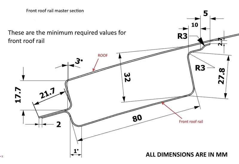
Given image is just for reference dimentions considered are as the given master section.
In order to meet the exact requirements of the dimentions we have created a datum plane on the edge curve with the dimentions given on the master section.
First offset the curve on the surface according to the width of the rail.
Then offset the sutface to the required depth of the rail
And trim the same with the curves
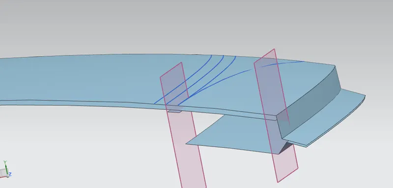
join them with proper blends
And give some reinforcement.to the rail.
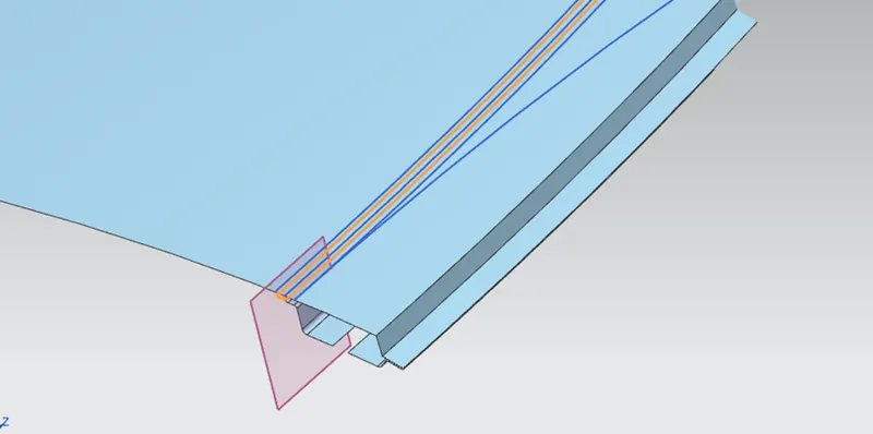
Edges are trimmed by using the plane which is offset from the datum plane and some reinforcement is govne to improve the rail strength.
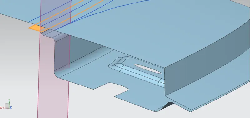
The same process is followed for all the roof rails.
Final front roof rail
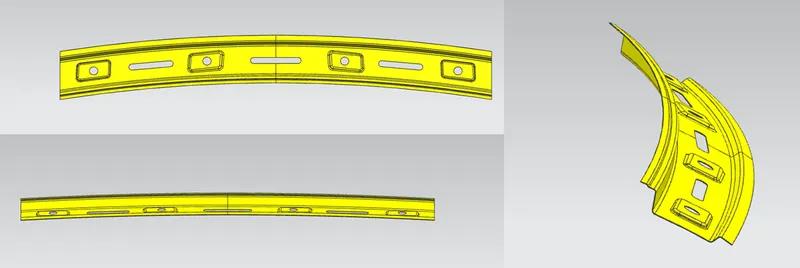
CENTER ROOF RAIL:
Master seection
This is considered for the center room rail and the reinforcement.
As the distance between the roof and the rail is too small we have considered it as minimum 5 mm.
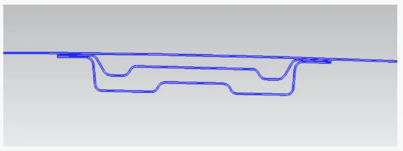
As followed the same process to make the center roof rail and its reinforcement.
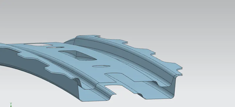
As it will rest on the other parts of the car bpdy for that we have provided a flange offset from the outer flange of the roof.
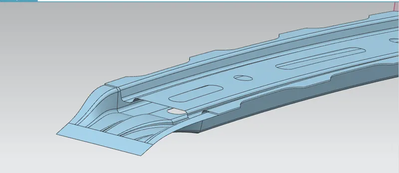
With all the reinforcements and cutouts the final Center roof rail will be,
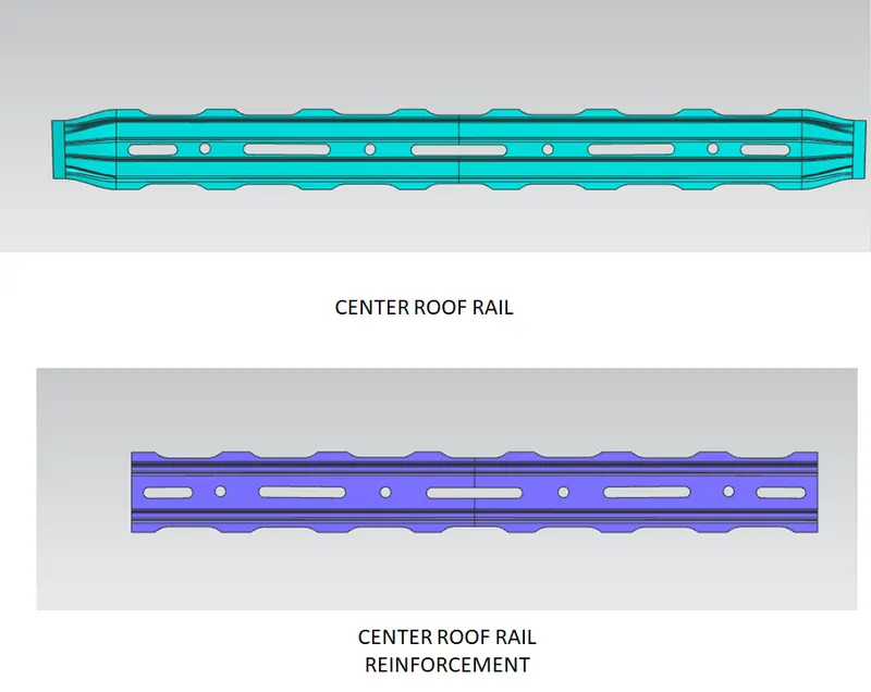
Together
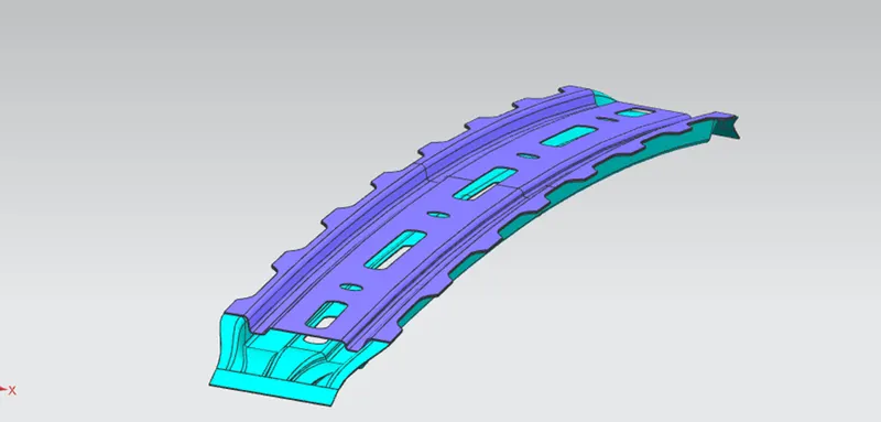
FRONT BOW ROOF RAIL
Master section
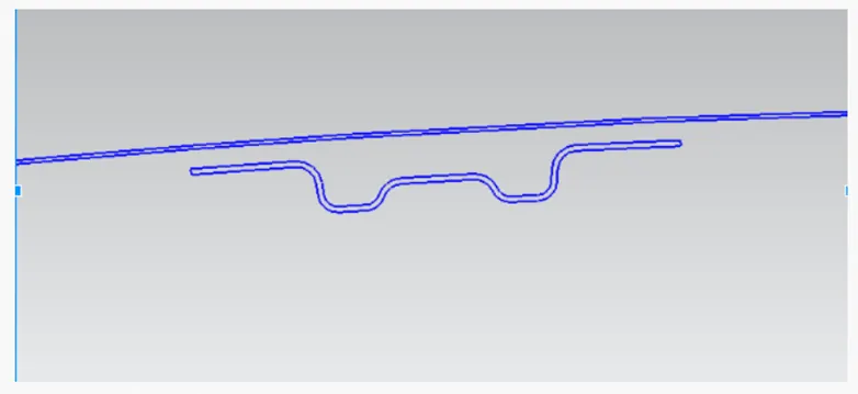
Same as the center bow roof will create the front and rear roof as well.
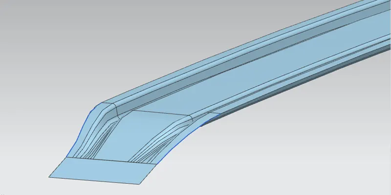
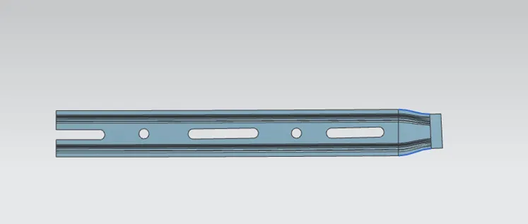
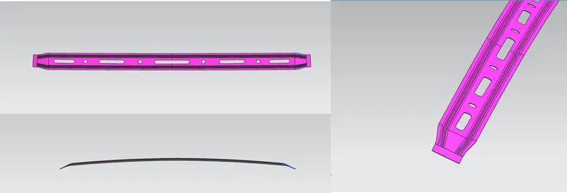
With all reinforcements,
REAR BOW ROOF RAIL
In the same way we process the rear bow roof,
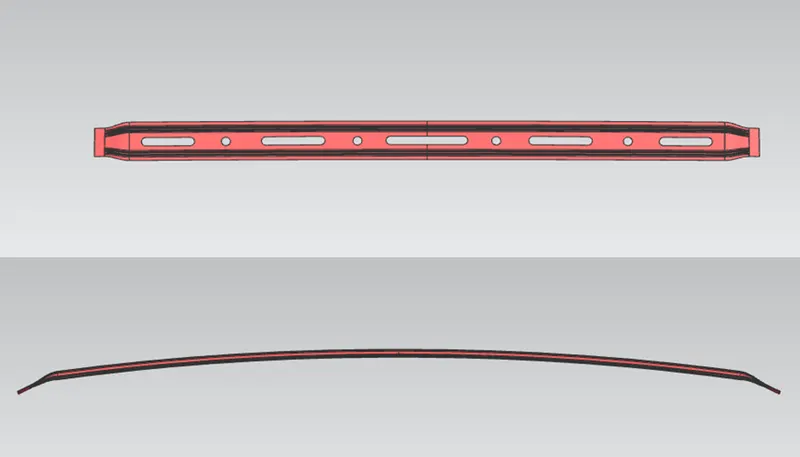
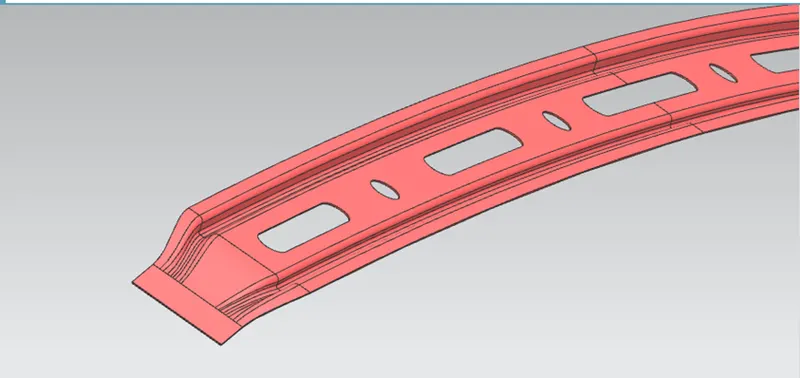
REAR ROOF RAIL
Even here same process is used to generate the rear roof rail according to the given dimentions.
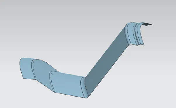
With all reinforcements and cutouts.
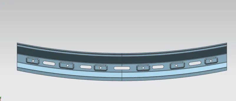
Final rear roof rail.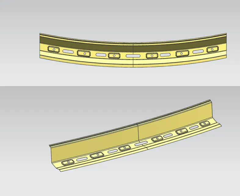
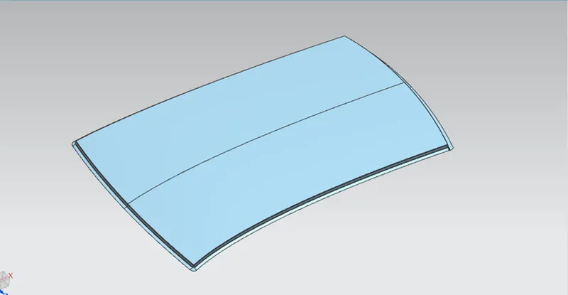
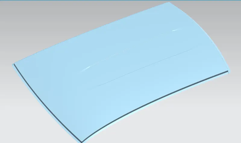
2.STYLING FFEATURE:
As it is not given in class A surface i have added a styling feature to it.
Before
After
3.FINAL JOINING AND THICKNING :
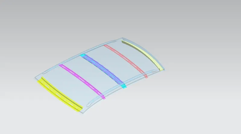
After all the sub elements are ready will put them together thickned and joined.
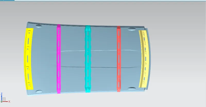
In different orientations,
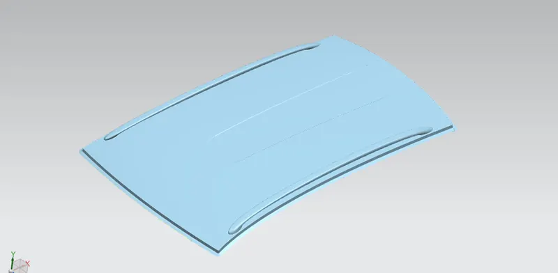
In the development process we have considered all the design rules to achieve the best out of it
3.DRAFT ANALYSIS:
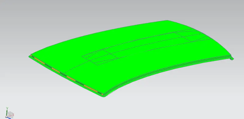
With the given information we have performed the draft analysis on the parts.
results shown below
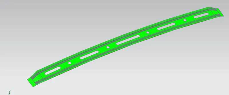
Roof
Front roof rail
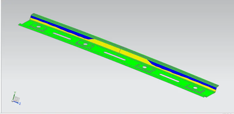
rear roof rail
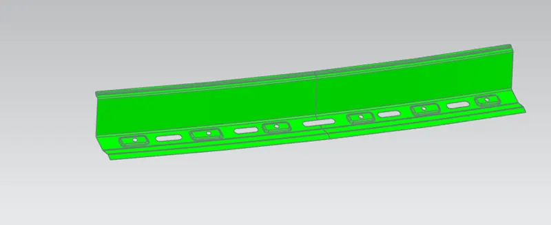
Center bow roof
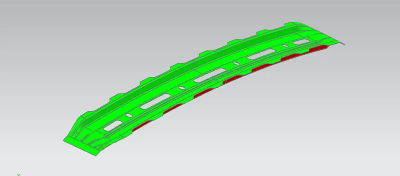
center bow roof reinforcement
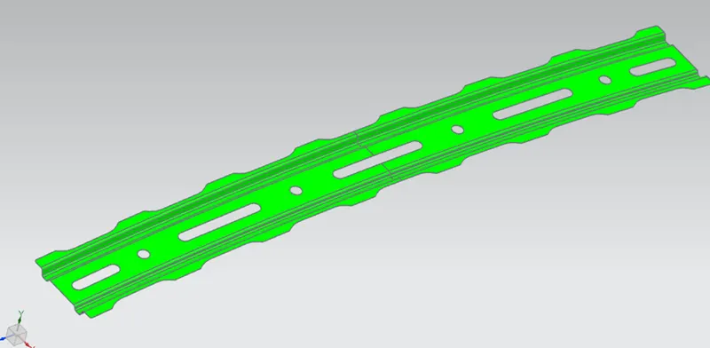
Fornt bow roof
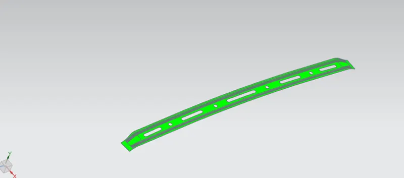
Rear boe roof
4.LOAD CALCULATIONS:
This is the stage will be able to know wheather our design is performing well or not.
Here we are going to consider the two conditions
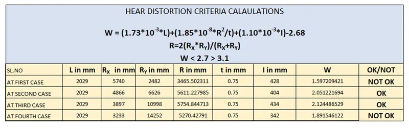
HEAT DISTORTION CRITERIA
W = [1.73 x 10^(-3) x L] + [1.85 x 10^(-8) x (R^2)/t] + [ 1.10x10^(-3) x l] - 2.68
L = Roof Length in X-Direction[mm](Roof dimension in 0-Y)
R = Roof curvature
R = 2(Rx*Ry)/(Rx+Ry)
Rx = X curvature
Ry = Y curvature
t = Roof plate thickness [mm]
l = Bow Roof Span [mm]
All the values are taken from the cad model the vlaues and results are shown below.
SLOW LOAD CALCULATIONS
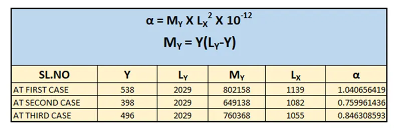
Qr = [Iy x t2] / [α x s x [(Rx + Ry)/2]2 x 10-8]
α = My x Lx2 x 10-12 , My = Y(Ly-Y)
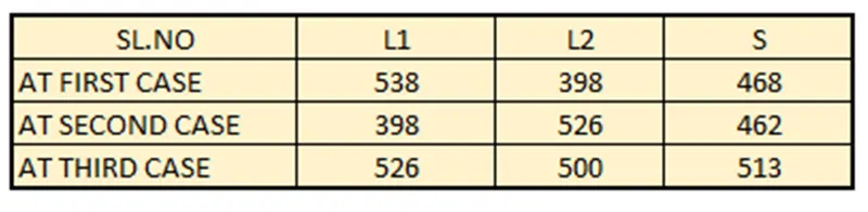
s = Distance for which Roof BOW bears divided load [mm]
s = L1/2 + L2/2
t = Roof plate thickness [mm]
Ly = Distance between the front and rear roof Rails on the Vehicle along with 0Y[mm]
Length of Roof panel with the center point between Roof rail Front /Rear as the front and rear reference point.
Lx = Distance between the Left and Right end of the roof on the Roof BOW [mm]
Width of the roof panel exposed on the surface.
Y = Distance front Front Roof Rail to Roof BOW[mm]
Iy = Geometrical moment of inertia of Roof BOW (Y cross-section )[mm4]
Rx = Lateral direction curvature radius of roof panel Y cross-section on Roof BOW [mm]
Roof panel curvature Radius of the Length Lx in Front view
Ry = Longitudinal Direction curvature radius of the Roof panel X cross-section on Roof BOW [mm]
Roof panel X curvature radius of length s in Side view

CONCLUSION:
From the results that we got form the calculations,
In the heat distortion criteria some additional support required at front and rear bow roof area.
Results from the snow load some aditional support required at rear bow roof area.
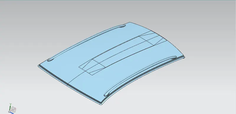
Taking all in consideration we have added aditional embosses at the roof which are shown in the following image.
BEFORE :
AFTER:
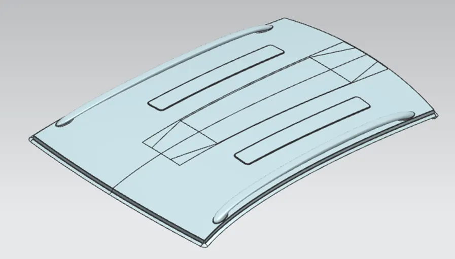
Rendered images are added for reference