Section Modulus calculation and optimization
SECTION MODULUS :
Section Modulus is the geometric property of the given cross-section of any shaft or beam structures. It is the direct measure of the strength of the shaft section or the beam section. Higher the section modulus of a structure, the more the resistive it becomes to bending.
Section modulus is defined as the ratio of Polar moment of inertia to the radius of the shaft or the distance from the neutral axis to the outer fibres.
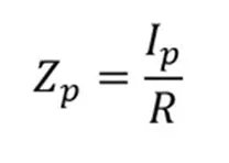
The common way of calculating Section_Modulus for a shaft requires is its diameters even if it is a solid or hollow shaft. If it is a beam (Square/rectangle in shape) then it will require the moment of inertia and the distance of the outer fibres from its neutral axes.
Following is the formula to calculate the section_modulus for the solid shaft.
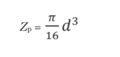
Where d is the diameter of the shaft.
If it is the hollow shaft then,
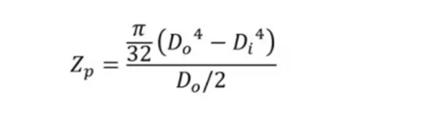
On the other hand, there are two types of section moduli, The Elastic Section_Modulus, and the Plastic Section_Modulus.
The Elastic section modulus has the same definition as the above-mentioned formula where it should be used for the materials which behave elastically under loading.
whereas the Plastic section modulus used for the materials which have Plastic behaviour as a dominant character.
The formula for the plastic section_modulus is defined as the sum of the product of the area of cross-section on each side of the plastic neutral axis and the distance from the local centroids of the areas to the plastic neutral axis.
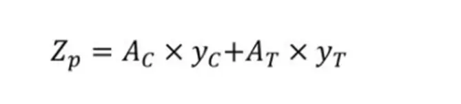
For the curent HOOD assembly we need to calculate the section modulus and on the basis we inprove the resuts with the changes.
Creation of Section :
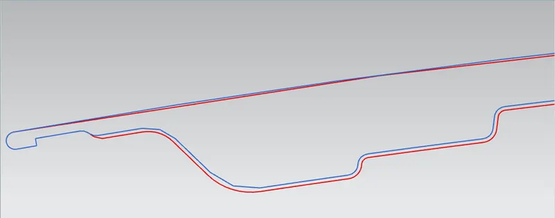
For the hood will consider the forntol area for which we need to create a plane on the curve.
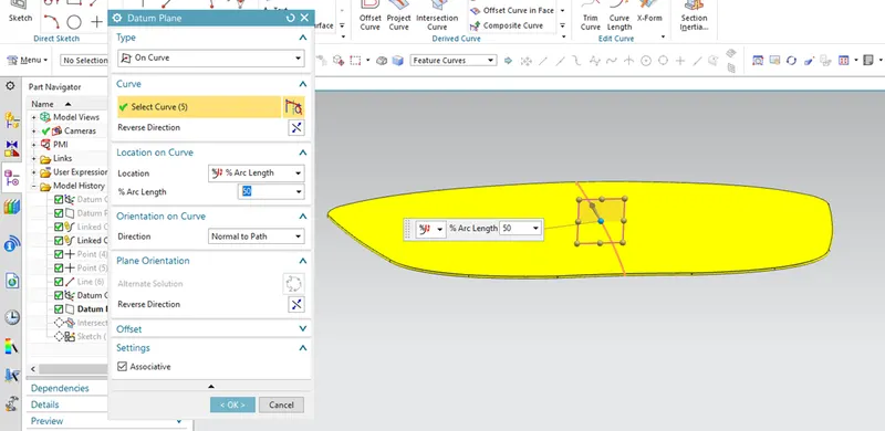
Along this plane will take inter section for both outer panel and the inner panel.
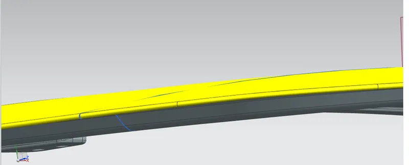
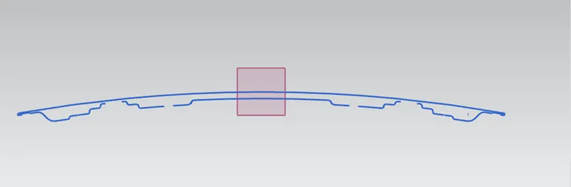
Then we need to extract this information in the 2D sketch for that we need to create a sketch and extract the lines in the sketch.
And in that sketch we need to consider the extreme lines on both the panels, rest of them to be trimmed.
Fill the gaps with the STUDIO spline By pole command which gives the tangent curves along the line.
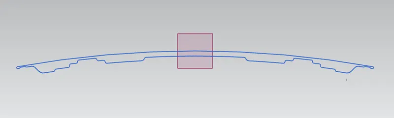
Which will finishes the sketch.
Form the SECTION INERTIA ANALYSIS tab will analysis the sketch to get the moment of inertia.
To calculate teh section modulus formula is S = I/Y
Here y is The extreme iatance ftomt the nuteral axis
I - Moment of inertia will get it form the analysis.
Actual section will get the following moment of inertia,
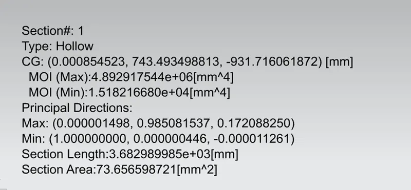
So results are shown below,
Maximum moment of inertia I - 4.8929 X 10^6 mm^4
Minimum moment of inertia I - 1.5182 X 10^4 mm^4
Y from the sketch is 442.64 mm
Section modulus is S = I/Y
MaximumSection modulus
= (4.8929 X 10^6 mm^4) / 442.64 mm
= 1.1053 X 10^4 mm^3
MinimumSection modulus
= (1.5182 X 10^4 mm^4) / 442.64 mm
= 0.3429 X 10^2 mm^3
In order to improve the HOOD strength i have off set the inner area of inner panel by 1 mm distance which gives me the following results.
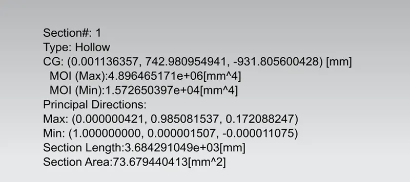
Maximum moment of inertia I - 4.8964 X 10^6 mm^4
Minimum moment of inertia I - 1.5726 X 10^4 mm^4
Y from the sketch is 442.64 mm
Section modulus is S = I/Y
MaximumSection modulus
= (4.8964 X 10^6 mm^4) / 442.64 mm
= 1.1062 X 10^4 mm^3
MinimumSection modulus
= (1.5726 X 10^4 mm^4) / 442.64 mm
= 0.3552 X 10^2 mm^3
With this offset there is increased alot in the minnimum moment of inertia and increased little in maximum moment of inertia.
Below curves are shown for reference and for results comparision.
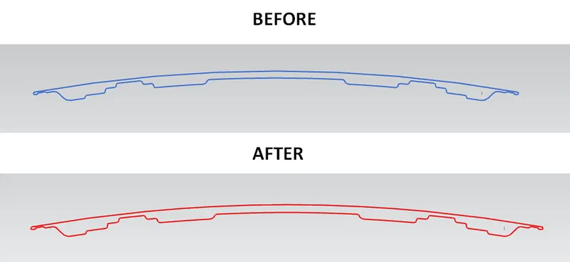
Close view