


Courses by Software
Courses by Semester
Courses by Domain
Tool-focused Courses
Machine learning
POPULAR COURSES
Success Stories

Week 8 - Challenge 5 - Core & Cavity Design
CORE & CAVITY DESIGN OF SWITCH BEZEL AIM1. To create the switch bezel plastic component through the given class-A-surface and at theperforming the draft analysis on the model.2. Creat the core and cavity design of the switch bezel component OBJECTIVE• To ensure proper tree structure is followed.• …
Nikhil KUMAR
updated on 14 Nov 2021


CORE & CAVITY DESIGN OF SWITCH BEZEL
AIM
1. To create the switch bezel plastic component through the given class-A-surface and at the
performing the draft analysis on the model.
2. Creat the core and cavity design of the switch bezel component
OBJECTIVE
• To ensure proper tree structure is followed.
• Geometrical sets should have a proper name based on the sketches present inside of them.
• All the sketches should be created under a geometrical set.
• Use of the close surface feature to make a solid body from the surface.
• To publish the tooling axis, Class A, B and C surface.
PROCEDURE
First import the class A surface of switch bezel model in CATIA V5.
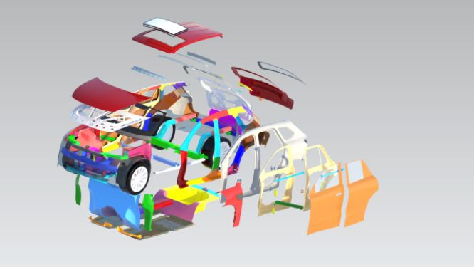
• The mould core and cavity are the shaped section in either half of the mould tool which gives the plastic
product its final shape.
• The hot molten material is injected into the core and cavity and then sets hard into shape. The design of
the core and cavity is essential in the correct formation of the product. The sequence of events during the
injection mould of a plastic part is called the injection molding cycle.
• The cycle begins when the mould closes, followed by the injection of the polymer into the mould cavity.
• A core is usually made of the best quality sand and is placed in to the desired position in the mould cavity.
Core prints are added to both sides of the pattern to create impressions that allow the core to be
supported and held at both ends.
PARTING SURFACE
Extract the boundary from the class-a surface and extrude the edges outside.
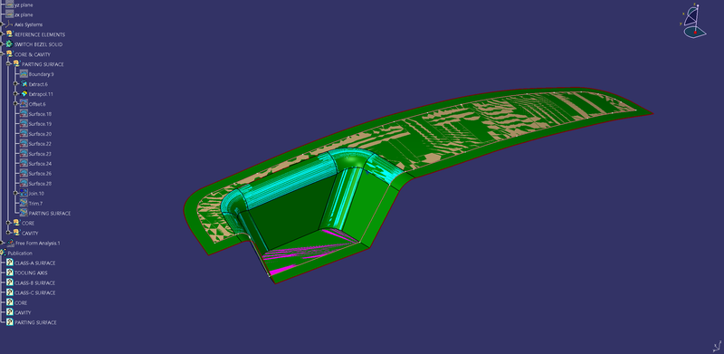
Offset the extruded surface 3mm downward and exude the boundary in the tooling direction.

Trim the offset with the class-a surface and boundary extrude. then you will get Parting Surface.

CORE
• The core design is started with extracting the parting surface that becomes the datum for the core and
cavity. The parting surface in most of the cases is kept at the B class surface to avoid close and tight
contact between the core and cavity.
• At first the A-class surface is extrapolated with some length and later it is trimmed with a C surface.
Sketch

Extrude

Trim extrude with parting plane

CORE

CAVITY
• The cavity is the part where the injector and filling of the molten plastic happens. The cavity block is
prepared by first extruding the outer boundary along the tooling direction.
• This outer surface is trimmed with the B class surface and then it is filled and thickened.


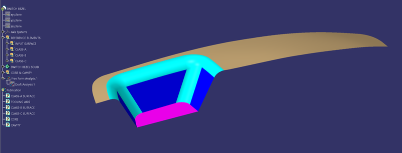
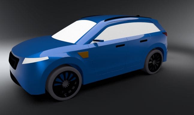
CORE & CAVITY WITH SWITCH BEZEL


DRAFT ANALYSIS
CLASS-A SURFACE

CORE

CAVITY

TREE STRUCTURE


Leave a comment
Thanks for choosing to leave a comment. Please keep in mind that all the comments are moderated as per our comment policy, and your email will not be published for privacy reasons. Please leave a personal & meaningful conversation.
Other comments...
Be the first to add a comment
Read more Projects by Nikhil KUMAR (19)
Week 9 - Attachment Feature Creation - Challenge 1
AIM:- RIB DESIGN INPUT- COIN HOLDER MODEL Introduction: Rib: Ribs are thin, wall-like features typically designed into the geometry of a part to add internal support to walls or other features like bosses. In a similar fashion, gussets are support features that reinforce areas such as walls or bosses to the floor. Ribs…

16 Apr 2022 04:22 PM IST
Week 8 - Challenge 5 - Core & Cavity Design
CORE & CAVITY DESIGN OF SWITCH BEZEL AIM1. To create the switch bezel plastic component through the given class-A-surface and at theperforming the draft analysis on the model.2. Creat the core and cavity design of the switch bezel component OBJECTIVE• To ensure proper tree structure is followed.• …
14 Nov 2021 01:22 PM IST
Door Arm Rest Week 8 Challenge
AIM: To make a model from the provided class-A surface. INTRODUCTION: CLASS-A SURFACE: A surface made by the designer which is given as an input to the plastic modeller to work on. It is an aesthetic surface and the outermost surface. CLASS-B SURFACE: A surface after a certain thickness from the class-A surface…
13 Jun 2021 12:24 PM IST
Week 8 - Challenge 4 - Coin Holder Design
AIM: To make a model from the provided class-A surface. INTRODUCTION: CLASS-A SURFACE: A surface made by the designer which is given as an input to the plastic modeller to work on. It is an aesthetic surface and the outermost surface. CLASS-B SURFACE: A surface after a certain thickness from the class-A surface…
25 May 2021 03:14 PM IST
Related Courses


Skill-Lync offers industry relevant advanced engineering courses for engineering students by partnering with industry experts.


Our Company

4th Floor, BLOCK-B, Velachery - Tambaram Main Rd, Ram Nagar South, Madipakkam, Chennai, Tamil Nadu 600042.

Top Individual Courses
Top PG Programs
Skill-Lync Plus
Trending Blogs
© 2025 Skill-Lync Inc. All Rights Reserved.