Core & Cavity Design of Switch Bezel
OBJECTIVE
To develop the Core and Cavity of the Switch Bezel component.
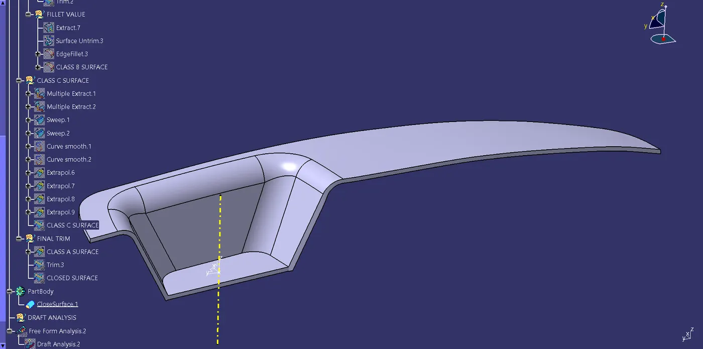
WORKING
Core and cavity are the molding halves that give shape to the part to be molded.
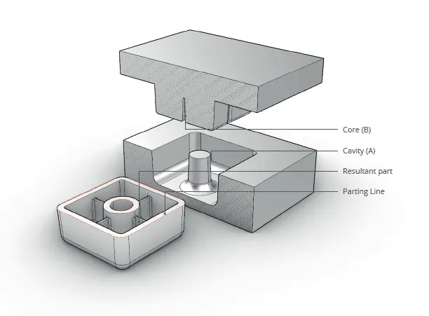
| Core |
|
| Cavity |
|
PROCEDURE
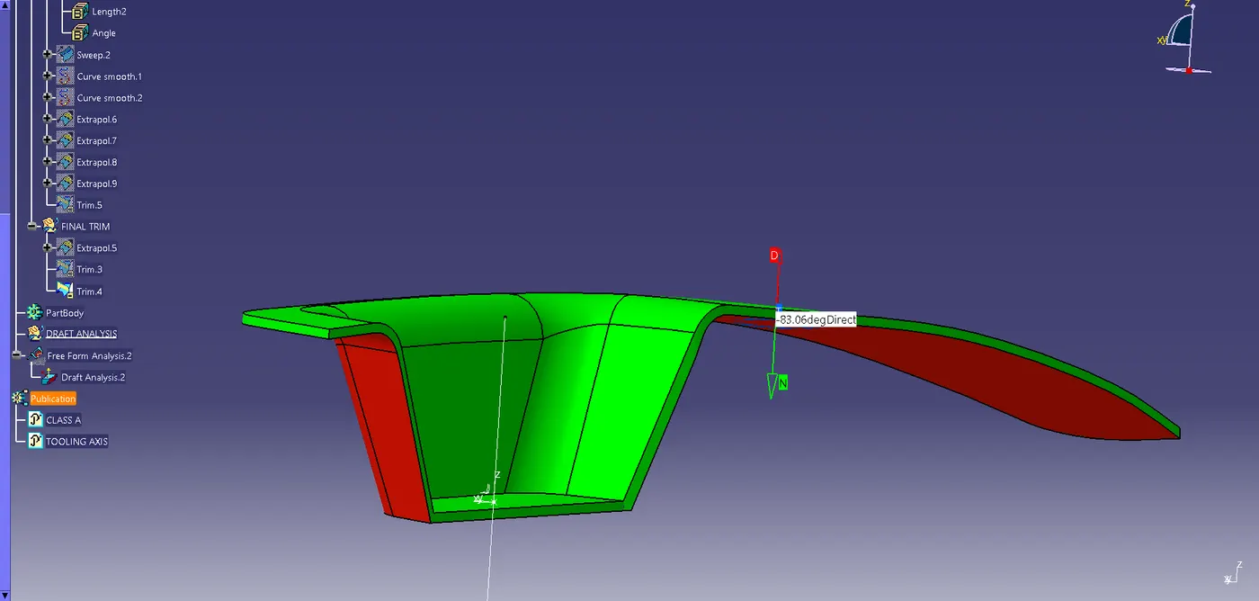
STEP 1: DRAFT ANALYSIS
All the surfaces must pass in this analysis.
Insert > Analysis > Feature Draft Analysis
Note: Ensure you have the Material view mode ON.
- Define the Draft direction using the "Compass" option.
- Drag the Axis system representation close to the model and align it along the tooling axis.
- "Lock" the Draft direction.
- Set the Colour scale
| Colour | Description | Value |
| Green | Core Side | Above 3 degrees |
| Blue | --- | 0 degrees |
| Red | Cavity Side | Below 0 degrees |
- Place the Analysis Tool (Arrow Icon) anywhere on the model and review the colours on the feature.
- If any feature is showing Blue/Red then choose the same option again (It will switch to Analysis under Running point) and place it on the respective feature to review the deviation of the sweep angle from the Tooling Axis.
|
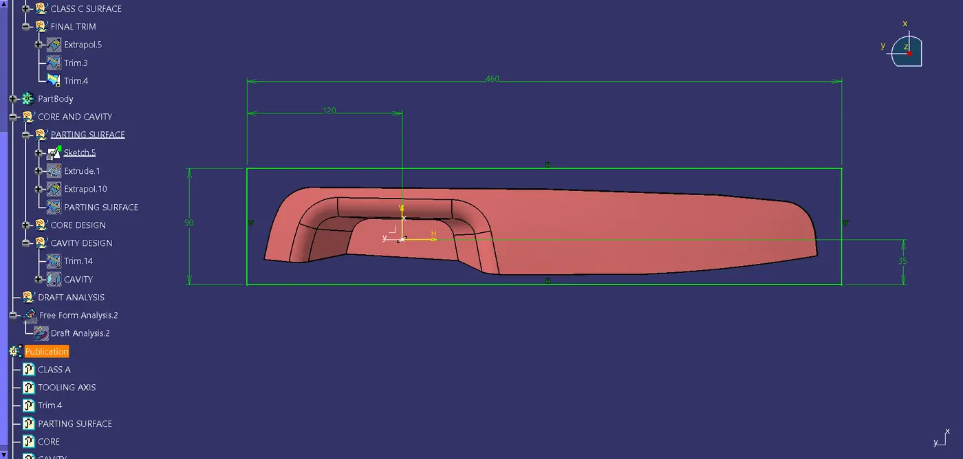
STEP 2: BOUNDARY |
|
 |
|
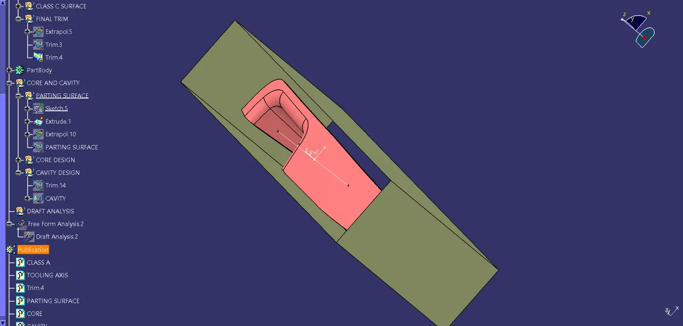
STEP 3: EXTRACT SIDEWALLS |
|
 |
|
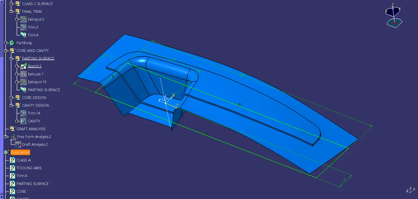
STEP 4: EXTRAPOLATE PARTING SURFACE |
|
 |
|
STEP 5: TRIM |
|
RESULT
|
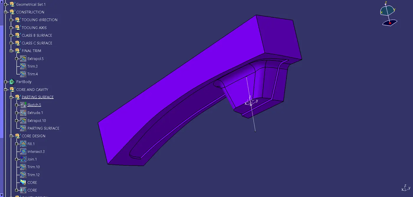
CORE: Has Projections and Features. |
 |
|
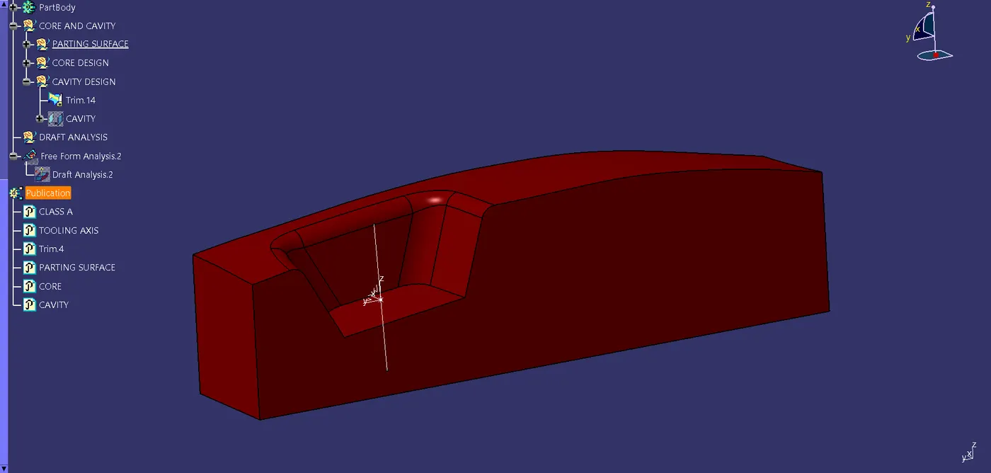
CAVITY: Has a Depression to accommodate the projection and features. The Parting surface separates Core from the Cavity. |
 |
|
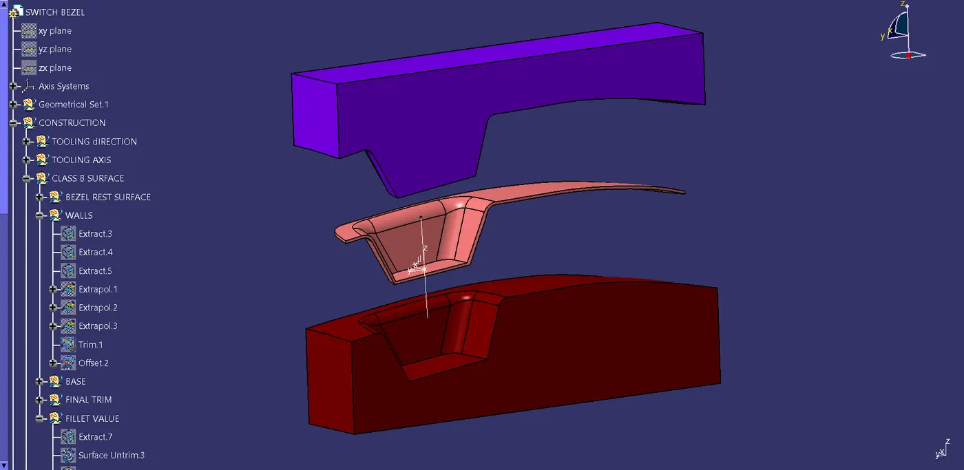
Component to be Molded |
 |
|
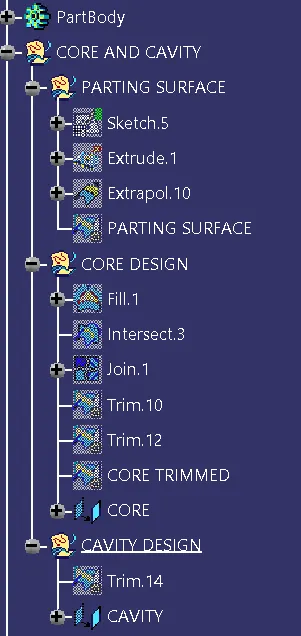
Tree Structure |
 |