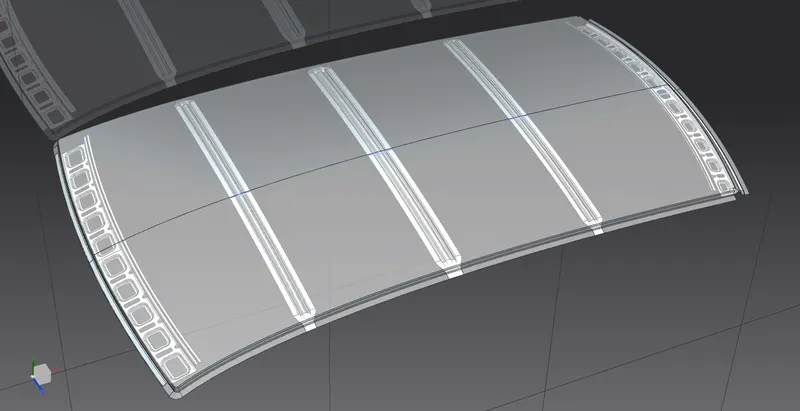
Roof challenge
BIW ROOF DESIGN FOR HEAT DISTORTION AND SNOW LOAD CRITERIA
To design an SUV Roof from the given class A and meet the required conditions:
- The design and functional requirements for the Roof and its components.
- Methods to increase the strength of the roof.
- Joining Techniques like Mastic and Welding.
- Meet the Gap and Flushness requirements.
PROCEDURE
STEP 1: INPUT
- We get the Class A surface with predefined edges from the Styling Team.
- We get a Master Section as well, which is a predefined sketch that is adaptable to different situations.
- As Design Engineer, we check for the initial feasibility and whether the part has to be raised/lowered.
Note: We don't have reference data, so we can go ahead with designing the engineering features.
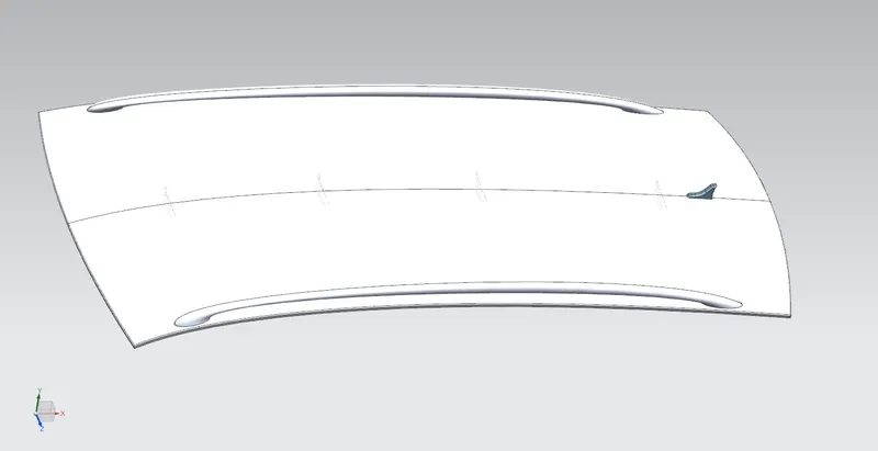
STEP 2: DRIP AREA REQUIREMENTS
- We extend the front edge of the roof from the styling point to provide clearance for the drip area.
- The clearances are given with respect to the visibility criteria, for the front passenger and driver.
Draft
- An optimum draft angle of 3 degrees is given to facilitate deep drawing conditions.
- An increase in the draft would affect the clearance for welding and sealants and therefore, we'd have to increase the flange length (beyond 21.5 mm) which indirectly affects the visibility criteria.
- A decrease in the draft angle would cause complexity for producing the part.
Drip Flange Length
- The maximum length is 21.5 mm to facilitate clearance for:
- Welding (8mm)
- Rubber Sealants (5mm)
- Assembly (2mm)
- Remaining to extend the draft
Drip Flange Height
- The Flange height is extended to give clearance for:
- Mounting Windshield
- Rubber Sealants (Thickness = 3.7 mm)
- Law extended by the Trial and Error method to provide clearance and pass the other 2 parameters mentioned above.
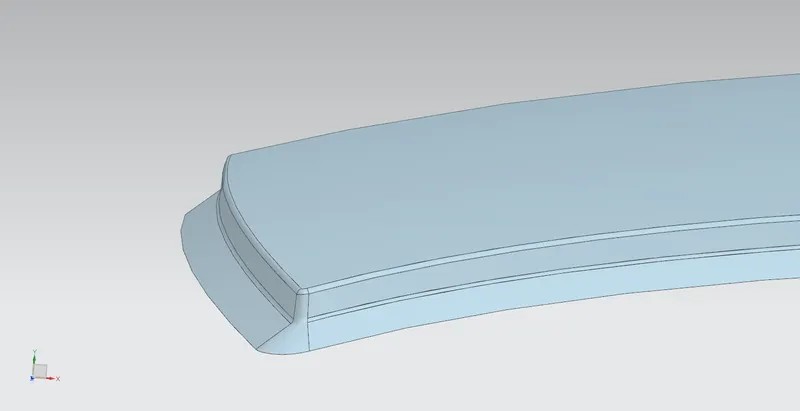
FRONT ROOF RAIL
- An additional commodity that acts as reinforcement with features supporting:
- Bracket Map Lamp
- Room Lamp
- Though it is a reinforcement component, it is made from the Outer Body Scrap having the same material and thickness (0.75 mm).
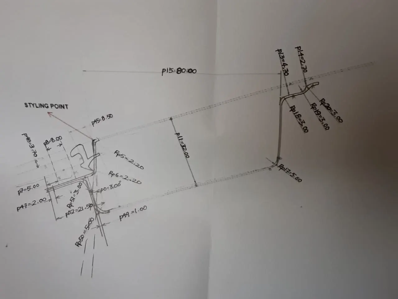
FR Rail Depth
- The Rail is offset by 32 mm to facilitate clearance for visibility criteria for the driver and passenger.
- The offset value depends on the average citizen's height, from region to region.
- No other reference data is given so we can go ahead with the conditions.
Draft
- An optimum draft angle of 3 degrees is given to facilitate deep drawing conditions.
- An increase in the draft would affect the clearance for welding and sealants and therefore, we'd have to increase the flange length (beyond 21.5 mm) which indirectly affects the visibility criteria.
- A decrease in the draft angle would cause complexity for producing the part.
Headroom Clearance
- The Headroom clearance is 80 mm from the given reference data.
- Again, the value varies from region to region depending on the average citizen's height and seating position.
Mastic Clearance
- A clearance of (2.7-3.7) mm is given to facilitate the positioning of mastic sealants.
- Mastics provide additional strength to the local region and an adhesive for joining the parts in the roof assembly.
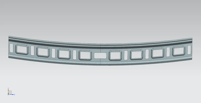
REAR ROOF RAIL
- The Rear Roof Rail also has a Drip area to provide clearance for mounting the Back door Hinge.
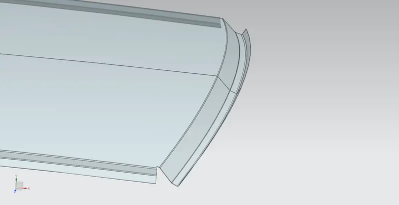
Drip Area
- Due to lack of reference data, we law extend the flange by trial and error to pass the Rear Roof rail criteria conditions.
- The Flange Length and extended Flange Height are given as 15 mm to provide space for the Back Door Hinge assembly and opening.
Rear Visibility Criteria
- The Rail is offset by 70 mm to facilitate clearance for visibility criteria for the rear passengers.
- The offset value depends on the average citizen's height, from region to region.
- No other reference data is given so we can go ahead with the conditions.
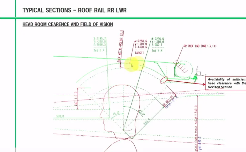
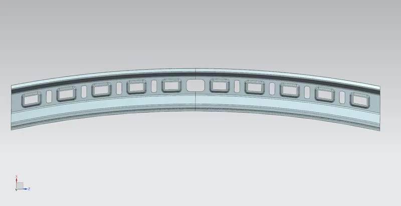
Rear Headroom Clearance
- The Headroom clearance is about 50-60 mm from the given reference data.
- Again, the value varies from region to region depending on the average citizen's height and seating position.
STEP 3: Bow Roof Design
Design Rules to be followed to meet Manufacturing standards:
| Draft Angle |
|
| Emboss spacing/clearance |
|
| Clearance for Material removal |
|
| Minimum Radius |
|
| Corner Reliefs |
|
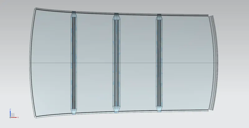
Functions performed for creating the Emboss:
| Offset surface |
Note: The Offset dimension is limited up to the Radius of the surface (if curved). But if the surface is complex, it gets distorted from a far distance, well within the limit. |
| Offset curve on surface |
Note: Ensure the curve gets,
|
| Trim sheet |
|
| Through curves |
|
| Law extension |
|
| Emboss |
|
| Face blend |
|
| Edge blend |
|
| Sketch Tools |
|
| Project Curve |
Note: We cannot sketch on a curved surface. Therefore, we sketch on a datum plane and project it onto the respective surface to get an accurate section of the sketch. |
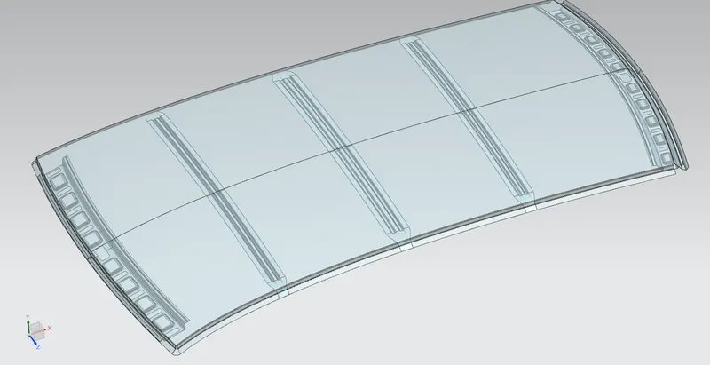
Draft Analysis
Draft Analysis is done to ensure the part follows:
- Zero Undercuts
- Minimum Fold requirement gaps
- Positive Draft for Ideal Deep Drawing conditions
| Colour | Description | Value |
| Green | Passes for Minimum Deep Drawing Condition | Above 5 degrees |
| Yellow | Needs work on those surfaces | 5 to 0 degress |
| Blue | Fails for Deep Drawing Condition | 0 to -5 degress |
| Red | Fails crucially for Deep Drawing Condition | Below -5 degrees |
| Roof with Drip Area | 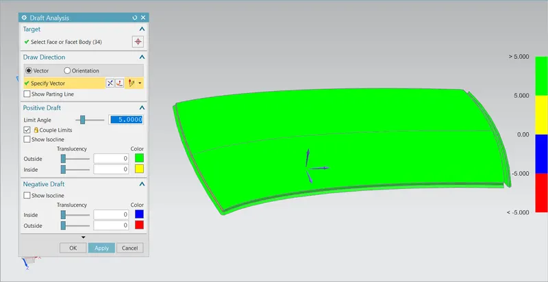 |
| Front Roof Rail | 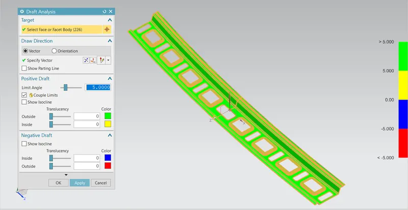 |
| Rear Roof Rail | 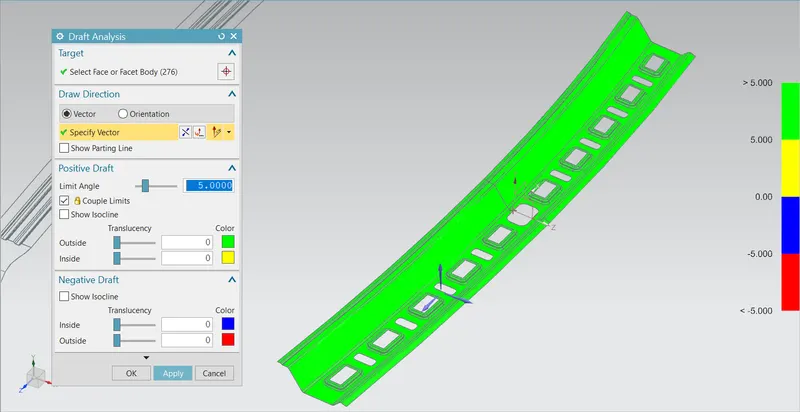 |
| Centre and Side Roof Bows | 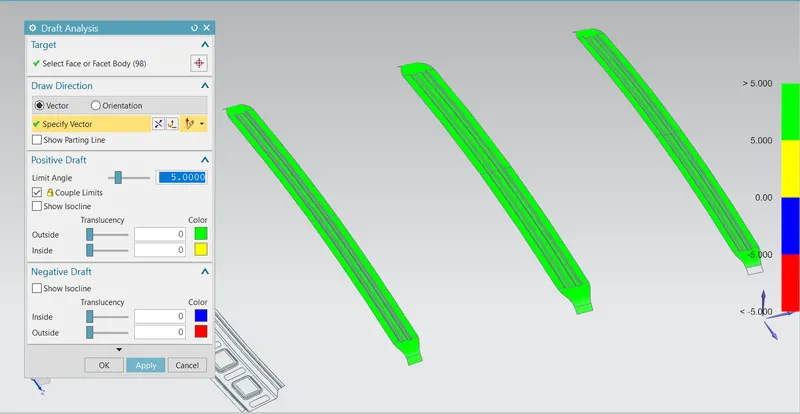 |
ROOF CALCULATIONS
HEAT DISTORTION CRITERIA
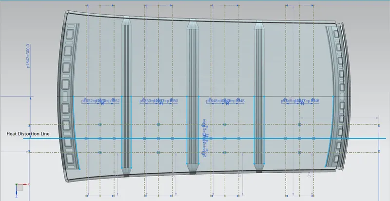
Prediction Formula:
W = `(1.73xx10^-3xxL)+(1.85xx10^-8xxfrac{R^2}{t})+(1.10xx10^-3xxI)-2.68`
Judgement Condition: `Ok<2.7mm<=NG`
| L : | Roof Length in X-Direction (Roof Dimension with OY) |
| R : |
Roof Curvature `R= 2frac{Rx xxRy}{Rx+Ry}` |
| Rx : | X Curvature |
| Ry : | Y Curvature |
| t : | Roof Plate Thickness (mm) |
| I : | Bow Roof Span (mm) |
| Sl. No. | BOWs | Rx | Ry | R | I | L | t | R^2/t | W | OK/NG |
| 1 | FR & 1st | 5731.5493 | 2669.5256 | 3642.514265 | 345.5058 | 2030.4972 | 0.75 | 17690546.9 | 1.540091654 | OK |
| 2 | 1st & CTR | 5076.7408 | 5775.0001 | 5403.405573 | 398.5589 | 2030.4972 | 0.75 | 38929055.71 | 1.991362477 | OK |
| 3 | CTR & 2nd | 4078.1913 | 10074.8917 | 5806.13223 | 423.564 | 2030.4972 | 0.75 | 44948228.63 | 2.130222786 | OK |
| 4 | 2nd & RR | 3327.4958 | 14278.6646 | 5397.224086 | 465.8073 | 2030.4972 | 0.75 | 38840037.11 | 2.063688873 | OK |
SNOW LOAD CRITERIA
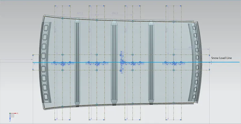
Prediction Formula:
`Q=frac{Iyxxt^2}{alphaxxsxx[frac{Rx+Ry}{2}]^2xx10^8`
Where
`alpha=MyxxLx^2xx10^-12`
`My=Y(Ly-Y)`
Judgement Condition:
`Qr<=3.1`
| t : | Roof Plate Thickness (mm) |
| Ly : | Distance between the front and rear roof rails on the vehicle along OY (mm) |
| Lx : | Distance between the left and right end of the roof on the roof BOW (mm) |
| Y : | Distance from FR roof RAIL Center to roof BOW (mm) |
| s : |
Distance for which roof BOW bears divided load (mm) `s=frac{L1+L2}{2}` |
| Iy : | Geometrical Moment of Inertia of roof BOW along Y cross-section `(mm^4)` |
| Rx : | X Curvature |
| Ry : | Y Curvature |
| Sl.No | BOWs | Iy | y | Lx | My | α | s | Rx | Ry | Qr | OK/NG |
| 1 | FR & 1st | 396.3197 | 440.7716 | 1134.1725 | 700705.8963 | 0.90135111 | 238.3582533 | 4496.1902 | 2650.379 | 8.126598057 | OK |
| 2 | 1st & CTR | 1173.6795 | 474.2786 | 1087.8153 | 738081.1789 | 0.873402552 | 238.4321213 | 3754.781 | 5766.1216 | 13.98931899 | OK |
| 3 | CTR & 2nd | 403.4295 | 499.7993 | 1059.0138 | 765041.7389 | 0.858002136 | 300.0301101 | 4215.9291 | 10378.4125 | 1.655495274 | OK |
RESULT
We have attained the Roof Panel to meet the desired requirements:
| Drip Area | |
| Front Roof Rail |
|
| Rear Roof Rail |
|
| Bow Roofs |
|