Preprocessing of Side Door Inner Panel using Hypermesh
Project 1: My Approach on Side Door Inner Panel
Objective
- Generate a clean Mid surface using manual cleanup.
- The model should have a good mesh flow.
- Learning shortcuts to save time and effort.
- Explore different tools to acheive the desired oucome.
- Find the most effective and efficient approach to get a good finished model.
Procedure
Step 1: Importing
i. Since we are importing a CAD geometry, the format will be either of the 2 industrial accepted standards:
a. STEP (Standard for the Exchange of Product data).
b. IGES (Initial Graphics exchange specification).
ii. When selecting the file for import, be sure to check if it is .stp or .igs.
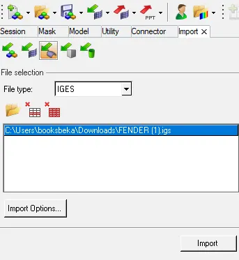
File > Import > Import Model > File type > Open File > Import File
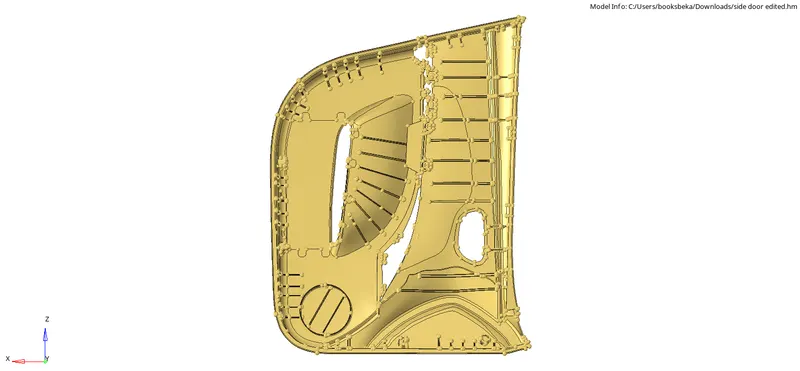
iii. We only have to work on the geometry, so before inspection check for solids and delete if there are any.
Delete [F2] > Solids > Displayed > Delete Entity

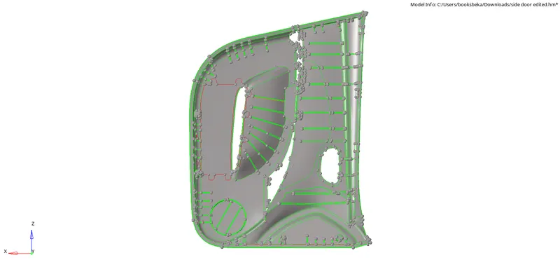
iv. Another way to check for solids is by switching the view to Topo mode [Option is available on top of the command window, which is right below the GUI].
v. If the model is highlighted in green that means solid is present.
vi. From the image below, we can confirm that there are no solids in the model.
Step 2: Inspection
2.1 Analyse
i. Analyze what kind of model it is and where it will be fit in the car.
ii. Upon visual inspection, we can confirm that it is a Side door Inner Panel.
iii. It consists of various features that look like:
a. Bottle Holder
b. Speaker Housing
iv. Space for placing the Windows' Control Panel and the Door Latch.
v. From practical experiences (most of us would've travelled in cars), we can most certainly confirm that it is a plastic component.
vi. It is most likely to have varying thickness, to confirm that, we will measure the thickness at various regions of the parent geometry.
2.2 Organise
i. From the initial inspection, we can observe that only the first component has the geometry, so delete the remaining collectors from the model tab itself.
ii. We can also observe that there are plastic rivets which means there are 2 components attached by the rivet.
iii. Due to a scanning issue, the solver shows it as a single component.
iv. As a CAE Engineer, we have to detach the component and move to a separate collector in the model tab.
Right Click on Model Tab > Create > Component > Give a different colour
v. The new component that we have created will be automatically set as the "Current Component".
Tools > Organise > Surfs (Select Manually) > Current Comp > Move
vi. Check if any undesired surfaces are selected to the new component.
vii. It is better to view "By Component" and select [Easier to view as different colours].
2.3. Check for Dimensions
i. As we are generating a mid surface from the geometry, we have to check for the thickness.
ii. Check for dimensions at various regions to ensure if the component has uniform or varying thickness.
iii. We cannot depend on Distance (F4) to check for thickness on plastic components as it only takes the dimensions at the edges.
iv. The best option is to project nodes on either side of the surface and measure between the nodes. [ Shortcut: Shift + F7]
Step 3: Geometric cleanup on parent
3.1 Defeaturing of ribs
i. As we are performing a 2D mesh, the elements cannot capture the feature properly.
ii. We are only going to generate a mid surface between the two long edges of the ribs.
iii. But the ribs have fillets which will directly affect her mid surface
iv. Therefore defeaturing them in order to get sharp edges is the best option to get a clean mid surface with good mesh flow.
3.1.1 Defeaturing tool
Geom > Defeature > Surface Fillets > Find Fillets in Selected

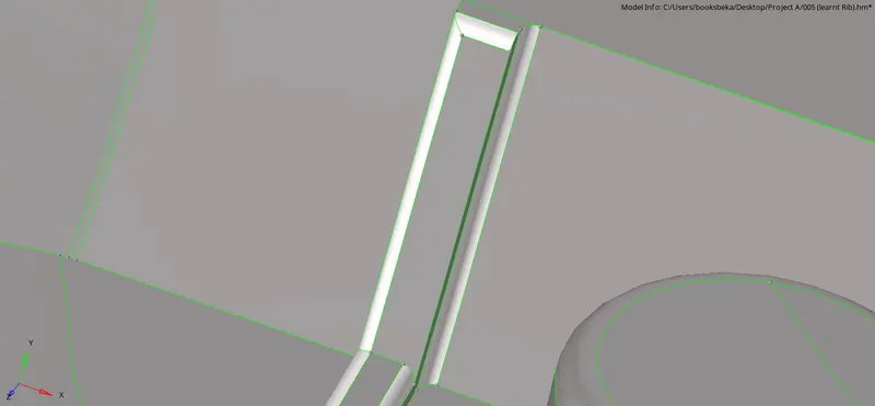
i. Select the surfaces .
ii. We need to enter the boundary conditions for the software to search for the fillets .
iii. Enter Min Radius = 0.1 mm & Max Radius = 5 mm
iv. Click Find
Upon clicking find, the solver will search for fillets within the given tolerance of the minimum and maximum radius.
v. The fillets within the tolerance will be highlighted.
vi. Click Remove to remove the fillets.

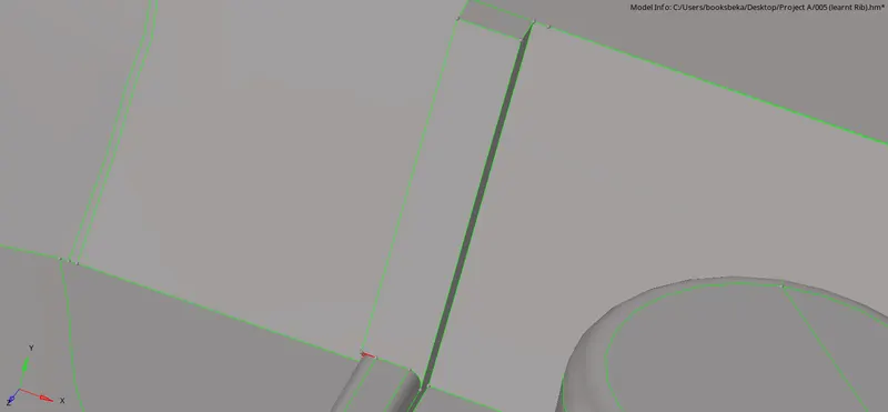
3.1.2 Limitations to the defeature tool
i. The fillets can be featured only along straight edges
ii. Some fillets extend upon curved surfaces and edges so defeaturing may not work in those regions.
iii. Therefore we have to manually defeature the curved fillets .
3.1.3 Manually defeaturing the ribs
i. We have to delete the code edges and replace with straight edges
ii. Once we delete the edges a gap will be present and we will fill the gap by extending the ribs
iii. Based on or conditions there are two options to extend the ribs, Drag along Line and Drag along Vector.
3.1.3.1 Drag along Line
i. I found this to be the fastest method to extend our trip up to the desired length.
ii. As the name suggests, we are dragging the surface along a line.
iii. If no line is present, use split surf node or split surf line to draw a perpendicular line up to the desired length.
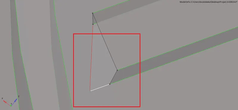
Geom > Surfaces > Drag along Line > Line list 1 > Line list 2 > Drag +

iv. Line list 1 specifies surface that you are going to extend by selecting the line of extension.
v. Line list 2 specifies the Line along which you are going to extend i.e., Direction you are extending.
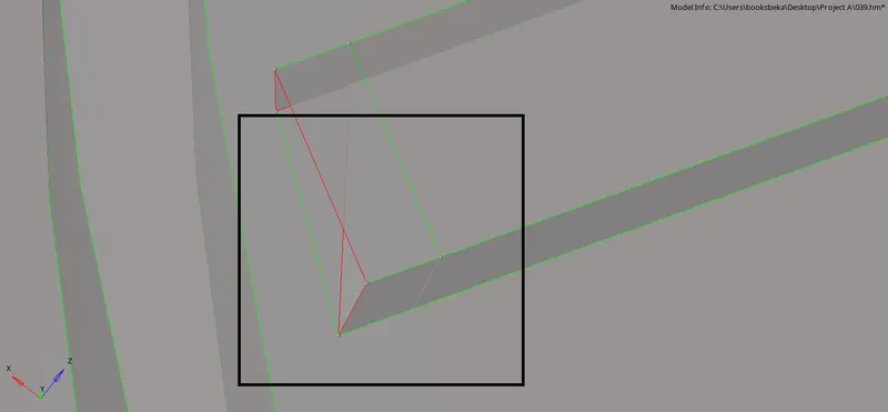
[Note: If the condition does not allow us to draw a perpendicular line then we can go with drag along vector.]
3.2 Projecting the Holes
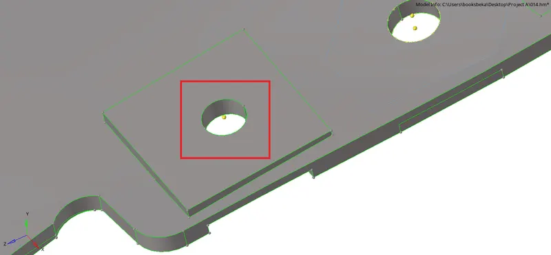
i. As we can see in the figure below, the hole is present on an elevated surface.
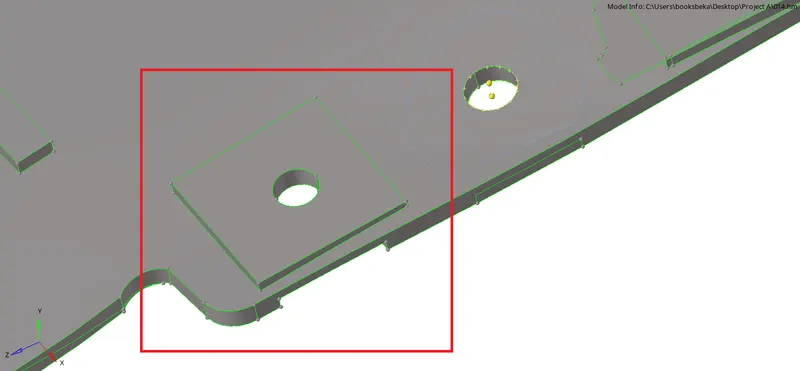
ii. In order to get a clean geometry, we need a hole that is present on the main parent surface.
ii. First measure the radius of the hole:
Geom > Distance [f4] > 2 Nodes > N1, N2 > Middle click
iv. Create a centre node with respect to the hole by using Nodes by arc centre:
Geom > Nodes > By Arc Centre > Select an Arc > Middle click
v. Delete the elevated surface:
Delete [F2] > Surfs > Select Manually > Delete Entity
vi. Fill the gap using surface Ruled:
Geom > Surface > Ruled > Line list 1> Line list > Middle Click
vii. Project the centre node on both the sides of the new parent surface.
Tools > Project [Shift + F7] > To Surface > Select Node > Duplicate twice > To Surface (select) > Along Vector (N1, N2 & N3) > Project
// N1, N2 & N3 specify the plane of projection. Just click on any 3 points on the selected plane you wish to project on //
viii. Create a circle with respect to the centre node:
Geom > Lines > Circle Centre and Radius > Node list > Centre Node (Circle centre) > N1,N2,N3 (Plane) > Radius > Create
ix. We have to trim the surface with respect to the circle created.
x. The reason we're trimming is that when we select within the circle the entire surface gets deleted.
Geom > Surface edit > Trim with lines > With Lines > Surfs (Select) > Freelines (Select) > Normal to Surface > Entire surface > Trim
xi. Delete the circles.
Delete [F2] > Surfs > Select Manually > Delete Entity
xii. Fill the free edges of the hole with surface Ruled.
Geom > Surface > Ruled > Line list 1 > Line list 2 > Create
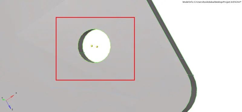
xiii. Now we have a closed volume.
xiv. The Hole is generated directly on the parent geometry which makes it easier to create a mid surface.
3.3 Fixing Overlapping Surfaces
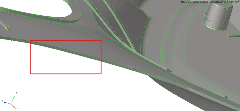
i. From the image below, we can see that it is difficult to view the point at which the surafces/edges are overlapping.
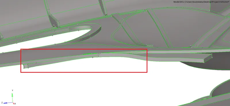
ii. So we release all the points and delete the extra surfaces.
Geom > Quick edit [F11] > Release Point > Select
iii. On replacing the points, the shared edges (green) will turn to free edges (red) and the connectivity is lost which makes it easier to delete the extra surfaces.
iv. We can delete the surfaces from within the quick edit panel itself.
Geom > Quick edit [F11] > Delete surf > Select
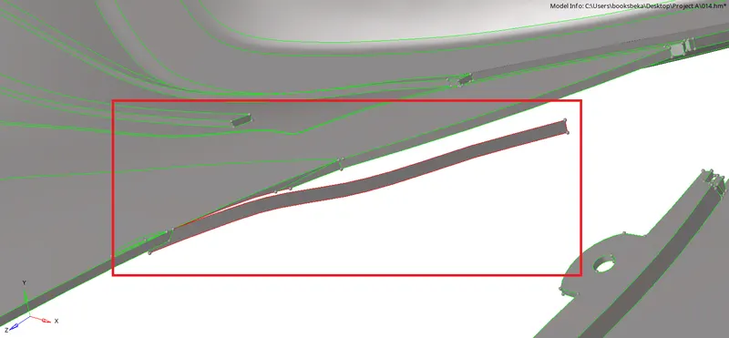
v. Now, we can establish connectivity back by just toggling the edges.
Geom > Quick edit [F11] Toggle edge > select
3.4 Fix Deformed surfaces
i. Deformed surfaces occur due to the following reasons :
a. Overlapping surfaces
b. Connectivity issues
ii. The error can be best rectified using the combination options :
a.Release point & Toggle edge
b. Add/Remove point & Replace point
iii. Release point
a. This allows the user to release the point causing a complex connectivity
b. Once the point is released the green lines turn to red, which means the lines pertaining to that point are disconnected from the geometry.
Geom > Quick Edit > Release points > Select the points to be released.

iv. Toggle option
a. If we want to Toggle a particular line :
Toggle Edge > Right Click on the line
b. If we want to untoggle a line :
Toggle Edge > Left click on the line

c. It is better to not rely on deleting a surface and creating a new one as it is a complex part, the features might not get captured properly.
Step 4: Extract the Mid surface
4.1 Check for Thickness of parent
i. Since it is a plastic component, we have to make sure if it has varying or uniform thickness.
ii. Using distance [F4] at the edges is not a viable option.
ii. so, we have to project nodes at random locations on both sides of the surface to ensure it has uniform thickness.
Tools > Project (Shift + F7) > To Surface > Nodes (Duplicate twice) > Surfs (Select) > Along Vector (N1,N2,N3)

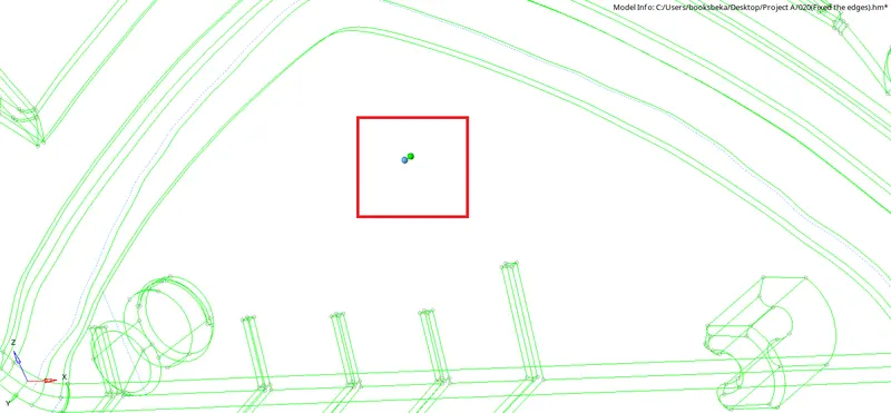
iii. Now use F4 to check the thickness of the surface
Geom > distance [F4] > Two Nodes > N1, N2 > Middle Click
iv. Upon projecting and measuring at various locations, we can confirm that the surface has uniform thickness.

4.2 Extract
i. Skin offset is the most effective option if one wishes to generate an auto mid.
ii. Due to the complexity of the design, the auto mid might not completely capture all the features and the CAE engineer might have to spend extra time in manual cleanup.
iii. Therefore in complex cases, it is best suited to manually offset the mid surface.
Right Click on Tab bar > Create > Component > Rename
Geom > Surface Edit [Shift + F9] > Offset > surfs > by Face > Duplicate to Current Component > Offset = 0.375 mm

iv. If arrow points outward, give for reverse normal to make the arrows point inward.
Vector Normal (if outward) > Reverse Normal
v. Blue indicates towards the screen or inward.
vi. Red indicates away from the screen or outward.
vii. If it shows Red, give for reverse normal and it should show blue.
Color Normal (If Red) > Reverse Normal
Color Normal (If Blue) > Offset
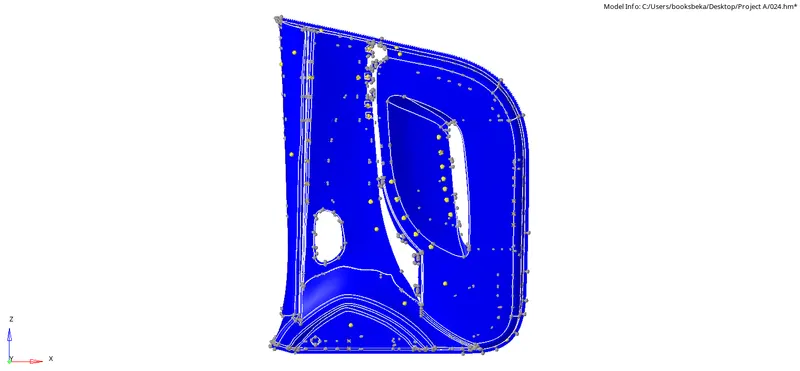
viii. Once the correct vector normal direction is confirmed, give for offset.
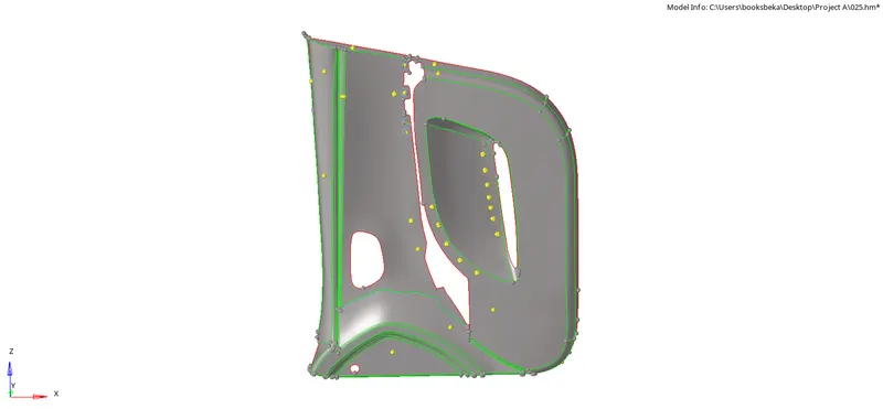
4.3 Assign Component
i. Create a New Component before extracting the mid for the next component.
ii. If we skip this step, then the mid surface for the next component will be saved to the previous one and an empty component will be created in the process.
4.4 Check for Duplicates
i. In some cases we can visually detect duplicates, there will be a glitch on the surface indicating that it is a dupliccate surface.
ii. But to be sure, we can check for duplicate from the defeature panel.
Geom > defeature > Duplicates > Surfaces (Displayed) > Cleanup Tol = 0.08 (Default) > Find > Delete

[Note: Upon clicking find the status bar will indicate the number of deleted surfaces and we just click delete to delete them.]
4.5 Extracting Mid of the Edges
Follow the same procedure as 4.1.
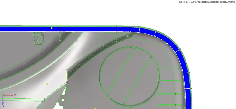
i. While Extracting the mid surface, we can notice that there are gaps between the extracted edges.
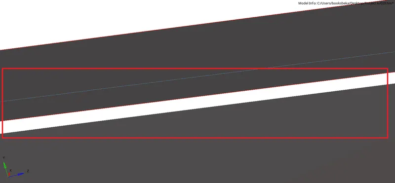
ii. This is due to the difference in the width of the top and bottom edges in the parent geometry.
iii. We can fill the gap by extending one surface till the adjacent surface.
iv. This can be done from within the Surface edit Panel [Shift + F9]:
Geom > Surface edit [Shift + F9] > Extend Extend over Edges > To Surfaces > Lines: To Extend Over > Surfs: To Target > Extend

v. We can get rid of the Non Manifold Lines (Yellow) by deleting the extra protruding surfaces.
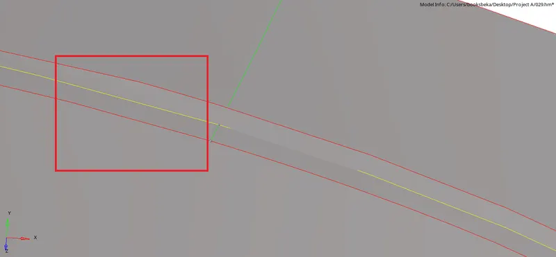
Delete [F2] > Surfs (Select) > Delete Entity
vi. Now we will have a mid surface with shared edges (green lines) which means that the connectivity is well established.
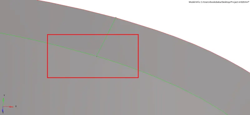
4.6 Extracting the Ribs
i. The conventional options we used so far to extract the mid are (for uniform thickness):
a. Auto Mid
b. Manual Offset
ii. The ribs have varying thickness along the length so we have to use a different option.
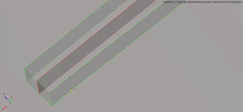
iv. This option is Final edit tools which is available under the Midsurface Panel:
Geom > Mid surface > Final Edit Tools > Surface Pair > Side 1 (Select Surf) > Side 2 (Select surf) > Extract

[Note: Check for Adjacent Mid surface]
v. One limitation to this tool is that we can select only one surface per side.
vi. so we have to make sure that the edge is selected along the entire rib. Id there are any splits in between then make sure to toggle the lines.
Geom > Quick edit [F11] > Toggle edge > Select Line
Note: When we use the tool to extract the ribsall the new mid surfaces extracted from this point onwards get assigned to a new collector that is automatically created by the Hypermesh itself.
4.7 Extending the Ribs to the surface
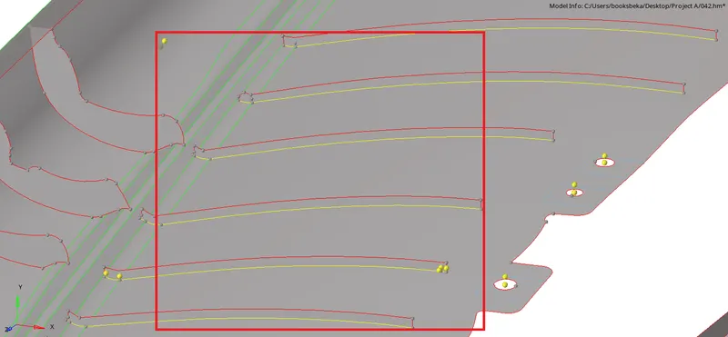
i. the extracted mids have the same height as the parent's so they are connected to the main mid surface.
ii. We have to connect the rib surface to the adjacent flat midsurface becasue:
a. To generate a closed volume in the finished component.
b. while meshing, node connectivity should be present.
c. During analysis, the forces have to be transferred on to all the surfaces via the nodes.
iii. We can extend the ribs from within the surface edit panel:
Geom > Surface Edit [Shift + F9] > Extend
[Note: Follow the same procedure as 4.5]
Step 5: Meshing
Before Meshing, we have to first input the quality criteria.
5.1 Enter the Quality Criteria
Quality criteria is predetermined according to industrial standard from testing of previous components.
|
Sl. No. |
Quality Criteria |
Function / Definition |
Value |
|
1. |
Aspect Ratio |
Ratio of Max. Length by Min. Length |
5 |
|
2. |
Skewness |
Deviation from the ideal shape |
45 |
|
3. |
Warping |
Angle between the 2 planes of the same element(Quad) |
15 |
|
4. |
Taper |
Convergence of a Quad element |
0.5 |
|
5. |
Min. Length |
Shortest length of any given element |
2mm |
|
6. |
Max. Length |
Longest length of any given element |
6mm |
|
7. |
Min angle Quad |
Minimum angle in any given Quad element |
45 |
|
8. |
Max angle Quad |
Maximum angle in any given Quad element |
135 |
|
9. |
Min angle Tria |
Minimum angle in any given Tria element |
20 |
|
10. |
Max angle Tria |
Maximum angle in any given Tria element |
120 |
|
11. |
Tria % |
Percentage of Tria on any meshed surface |
10 |
5.2. Rules to be followed for Meshing
Before beginning to Mesh, there are some certain rules to be followed regarding Tria Management, in order to generate a good mesh flow:
i. No Opposite Trias
ii. No Trias on edges (Especially Free Edges)
iii. No Trias on Corners
iv. Avoid Trias on Fillets
v. Avoid Rotating Quads
[Note : Trias are more stiffer elements than Quads and therefore, if they are in the regions as mentioned above, the part is most likely to fail in those regions. Therefore, it is best to perform meshing by keeping those rules in mind.]
5.3 How to begin Meshing
While Meshing we have to select the right type of Mesh to get a good mesh flow :
a. Quads : For Rectangular/Square surfaces
b. Mixed : For Irregular surfaces
[Note : Begin meshing from the regions of : Least Free Edges (or) More Features.]
Start meshing from the following regions:
i. Least Free edges
a. Ideally from the centre (depends on the part) and working our way towards the edges.
b. Reason : It becomes easier to clean up and requires less fixing/changes.
c. Mesh density plays a big role in starting with meshing.
d. If we start from the edges and work our way towards the centre, we might face erros as we might've been wrong in selecting the appropriate mesh density.
ii. More Features
a. Since it takes more effort to get a good feature capturing, it is advisable to start from there.
b. Reason :Less time consuming and less prone to errors.
c. It is easier to clean up on flat surfaces. Therefore, if we start from there and get the Mesh density wrong we have to start all over.
5.4 Begin Meshing on surfaces [F12]
i. Select the appropriate mesh based on the shape of the surface.
2D > Auto Mesh > "Surfs" > Element size = 5mm > Mesh Type : Quads or Mixed > Check for align and size > Mesh

ii. Once we give for mesh, we can edit the mesh density by changing the number of nodes.
iii. After trial and error, select the best combination of density by following the Tria Management rules.
Note for Meshing on surface:
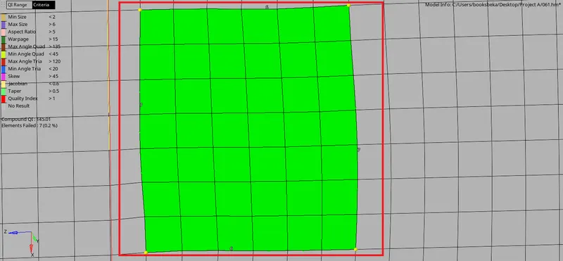
i. If it is a rectangular surface, Mesh type : "Quads" is the best option giving a good mesh flow.
ii. Don't forget to check for "Link opposite edges with AR <"
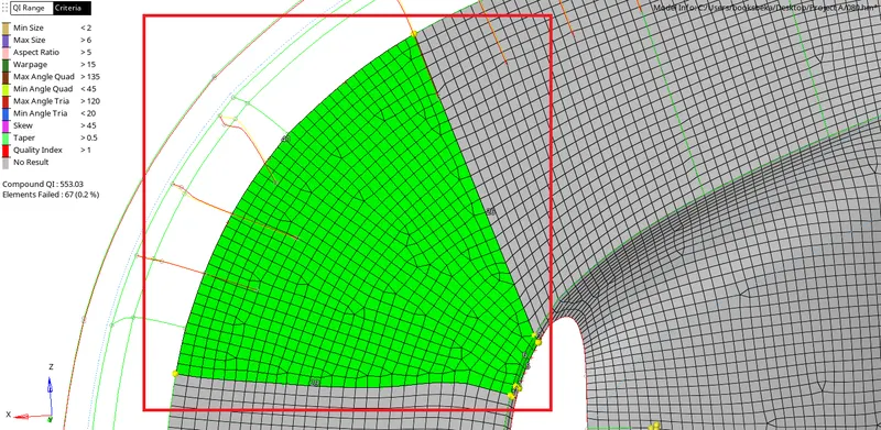
iii. If the surface to be meshed is not geometric (or irregular), we have to go with the "Mixed" Mesh type. It consists of Quads and Trias.
5.5. Give for Remesh on respective elements [F12]
i. To get better mesh flow on complex surfaces, give for remesh by selecting the elements.
2D > Auto Mesh > "Elems" > Mesh Type : Quads or Mixed > Mesh size = 4mm > Check for Align and size >Mesh

ii. If we wish to remesh the entire surface:
Elems (Right Click) > By Geoms
iii. If we wish to only remesh a certain region of the surface :
Box select [Shift + Drag].
iv. To get better results, box selecting a square/rectangle or even till the edges if you can.
[Note: On comparing the last 2 images, we can observe that a better mesh flow is achieved along with reduction in trias.]
5.5.1. Reasons for giving Remesh
i. Almost half the clean up gets done by selecting the appropriate elements.
ii. Saves half the time and effort spent on Clean Up (Quality Index).
iii. Generates a much better mesh flow with most of the quality criteria.
5.5.2 Rebuild Mesh
i. We use this option whenever there is a time constraint.
ii. It may or may not provide a good mesh flow on the surface. It depends.
iii. after meshing the surface, we can either go with Mesh elems or Rebuild Mesh which ever gives the best mesh flow for the geometry.
2D > Rebuild Mesh > Elems > By Geom > Select Surface > Rebuild.

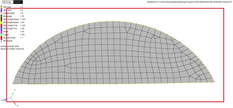
iv. One limitation to this tool is that the trias won't be in the desired direction of the mesh flow.
v. From observation, I've found that the biggest difference between the 2 options is:
| Mesh with Elems | Rebuild Mesh |
| Forms rotating Quads in complex surfaces and features. | Forms Pattern Trias in Complex surfaces and features. |
[Note: From my observation, this is not true in all cases but in most cases it is does.]
5.6 Check for Unmeshed Surfaces
i. We can check for unmeshed surfaces from the Mesh panel [F12] itself.
2D > Automesh > Unmeshed

ii. The status bar (in the bottom left) will indicate the number of unmeshed surfaces.
iii. The unmeshed surfaces will be highlighted in the GUI.
5.7 Meshing surfaces consisting Circular free edges
i. When any surface has a circular hole, before confirming mesh make sure that the number of nodes are even by altering the mesh density in that region.
ii. After gving for mesh, the nodes may not be aligned with respect to the geometry. Therefore we have to align and make the hole parallel to the geometry surface.
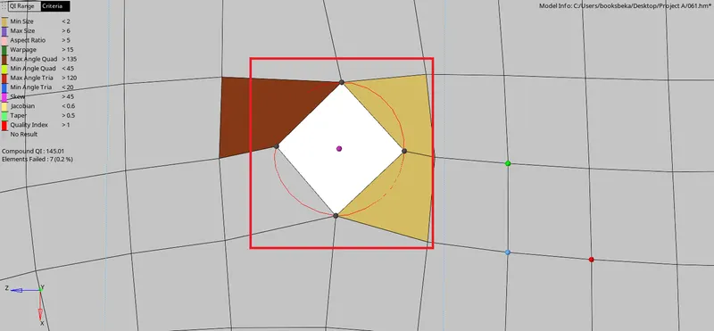
iii. In order to do that, we have t0 create a center point and rotate the nodes about that center.
Geom > Nodes > Arc Center > Lines > Select the Red Circle (Free edge) > Create

Tools > Rotate > Nodes (to be rotated) > Select N1, N2 & N3 > Select B > Give angle > Rotate +/-

v. N1, N2 & N3 can be any nodes on the surface, it is used to specify the plane about which we are rotating.
vi. B : base point, is the point about which we are going to rotate the nodes. In this case, it is the center point/node that we have created.
vii. Rotate the nodes about the center point/node and then remesh.
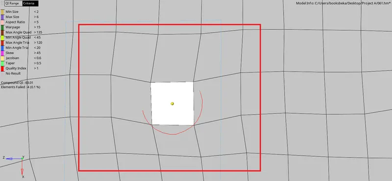
[Note: Since multiple errors have been created we have to give for remesh. But make sure to anchor the nodes of the circle otherwise the mesh will get distorded again and we have to repeat the the above procedure.]
The "Anchor Nodes" option is available in the Mesh Panel itself (as shown in the figure below).

Step 6: Fixing for Quality
6.1 Using Clean Up tools [Q]
This option allows us to make any changes to the elements on the mesh.
2D > Quality Index [Q] > Clean Up Tools
The tools are listed below:
|
Sl. No. |
Tool |
Function |
Advantages |
Limitations |
|
1. |
Smooth |
Clears the quality directly by just box selecting the elements |
Instantly clear for quality criteria. |
Overdoing affects feature capturing |
|
2. |
Drag Tria Element |
Drag any tria across the mesh flow |
Easily Join 2 opposite Tria elements |
|
|
3. |
Swap Edge |
Swag edge from one element to the next |
Individually fixing elements |
Only within the same surface. |
|
4. |
Split Quad Element |
Splits a quad into 2 Trias |
Reduce Rotating Quads |
Doesn't work all the cases. |
|
5. |
Combine Tria Elements |
Combines 2 Tria elements into 1 Quad |
Reduce Tria percentage |
|
|
6. |
Element Optimize |
Smooths the quality by just clicking on the element |
Clear for quality |
Affects feature capturing |
|
7. |
Place Node |
Allows the user to manually change the position of a single node |
Manually work on the individual element and fix for the quality |
Accuracy |
|
8. |
Split /Collapse edge |
Split the edge of the element that is along the free edge (red line) |
Reduce Trias at the free edges |
Might cause Quality error |
6.2 Getting good Mesh flow
i. After fixing for quality in a surface, give for Smooth Mesh to give a clean look.
Shift + F12 > Elems > Select > Iterations = 20 > Smooth

ii. This smooth operation is different from the clean up Smooth.
iii. This smooth alligns the elements in an orderly fashion to get a good flow.
v. If any errors reappear(Eg. Max Length) give for Clean Up Smooth in that region.
[Note: This Smooth doesn't take the quality into account]
6.3 Allign the Nodes across the Edges
Upon giving the Smooth Mesh, if the Edge elements cross over the shared edge and enter into the neigbouring surface we can Project [Shift + F7] them back into the current surface.
Tools > Project > To Line >Select Nodes > Normal Lines

6.4 Clean up using Distance [F4]
i. Using this option we can fix any element that fails for the errors listed below:
a. Min Length
b. Max Length
c. Min Angle Quad
d. Max Angle Quad
e. Min Angle Tria
f. Max Angle Tria
ii. Using F10,check for the node at which it is failing and use the Distance option.
iii. The following procedure briefly explains how to use the Distance tool:
iv. When the element is failing for either of the above mentioned errors, Press F4 which is the short cut for Distace tool.
Geom > 2 Nodes > select N1 & N2 > Change the "Magnitude" accordindly > Press Tab
6.5 Translate [Shift + F4]
i. This option allows us to fix warpages.
ii. Using F10 and clicking on the warping element, check for the node at which we can use the translate option.

iii. If it is difficult to detect the node at which the element is failing, we can mask the element alone, reverse and view it.
Mask [F5] > Elems > Select > Mask > Reverse all

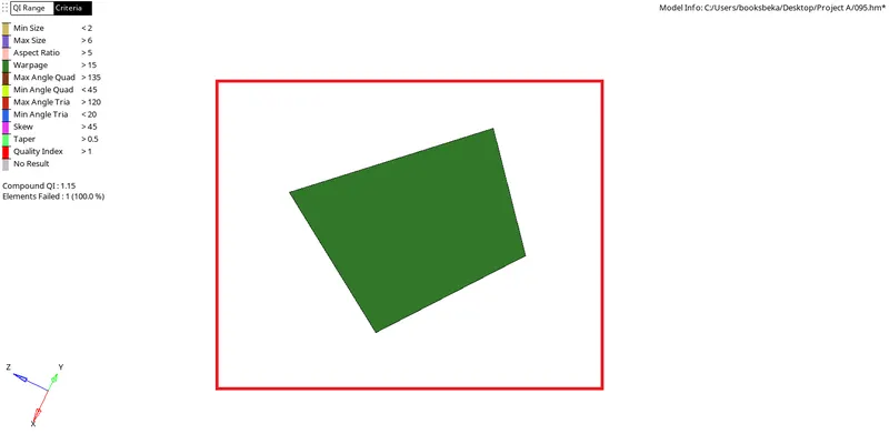
iv. By using Mask Adjacent we can visually detect the node at which it is starting to warp and use Translate option to fix it.
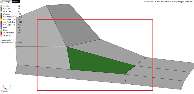
Tool > Translate > Node > N1, N2 & N3 > Magnitude > Translate +/-

v. Nodes are the Node that you wish to translate with respect to the surface that is defined by selecting the points N1, N2 & N3 (select the rest 3 points of the quad element you have masked).
vi. Therefore, the element itself acts as the reference plane.
vii. Set the magnitude to the desired value, ideally keep 0.05-0.100 mm.
viii. Depending on the direction of warpage, give translate +/- inorder to bring the element close to a flat plane.
ix. If the element warps downward, give for translate +.
x. If the element warps upward, give for translate -.
xi. The picture below represents the same element that is fixed from warpage using Translate [Shift + F4] tool.
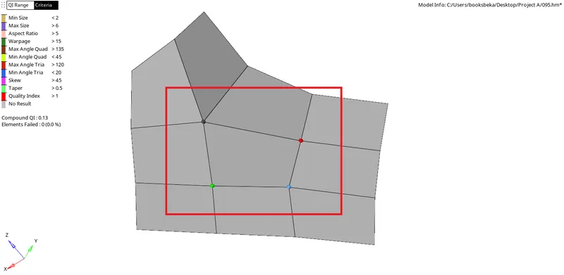
[Note: If it is difficult to view the node at which the element is warping, we can use Unmask adjacent. This unmasks the neighbouring elements and allows us to view better.]
6.5.1 Translate for fixing Row of Elements
i. If a row of elements are failing for Min or Max Length error, we don't use Distance [F4] option and fix each element individually.
ii. We can select the nodes by path and specify direction by only selecting N1 & N2.
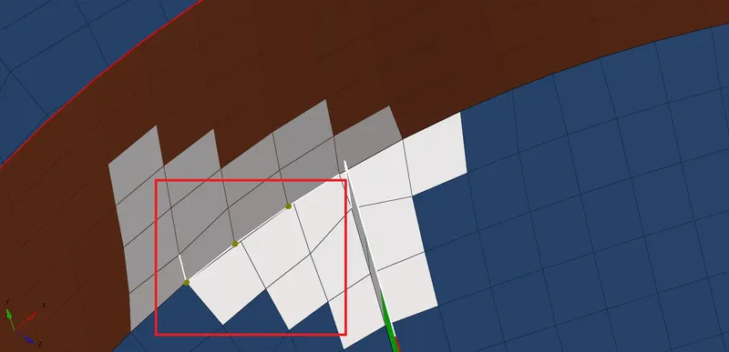
iii. Upon Translate +/-, the nodes will be translated in that particular direction and the error wil be fixed in all the elements (as shown in the figure below).
Step 7 : Check for Free Edges
i. Before we reflect, we have to check for free edges (red lines) in the component.
ii. Edges Tool will help us find this error:
Tool > Edges [Shift + F3] > Comps > Select > Tol = 2 > Find edges

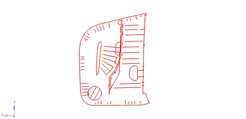
iii. Once we give for find edges, a component will be created, we can go to tab bar and view it.
iv. The free edges will be highlighted in grey/red lines.
v. Once we find the edges, we have to preview:
Tool > Edges [Shift + F3] > Comps > Select > Tol = 2 > Preview Equiv > Equivalence
vi. When we give for Preview, the nodes will be highlighted in yellow points.
vii. Once we give for Equivalence, the yellow points will dissapear and the free edges are deleted.
Reason for fixing fre edges :
i. If free edges are present, connectivity won't be establisihed between the surfaces.
ii. As a result, when force is applied on any surface it won't be distributed to the neighbouring surface due to connectivity issue.
[Note : The tolerance for Find edges and Equivalence is : 0.01mm to Minimum length]
Step 8: Assigning thickness to the Elements
8.1 Review Thickness
i. Check for thickness of the surface using review thickness:
Geom > Mid surface > review Thickness > View thickness > Surfs > Select
ii. Three different parameters will be produced after selecting the surface:
a. Average Thickness
b. Max. Thickness
c. Min. thickness
iii. In most cases, we can just set the average thickness for the elements.
8.2 Creating Component and Property
i. As different elements will have different thickness, we have to assign them to their respective collectors.
ii. Create a new component:
Right Click on Tab Bar > Create > Component > Rename : RIB_" "
[Note: For reference purposes, I've entered the Thickness in the component name. Eg. RIB_2P5]
iii. Create a new property:
Right Click on Tab Bar > Create > Property > Rename : T_ " "
[Note: For reference purposes, I've entered the Thickness in the Property name. Eg. T_2P5]
Enter the Avg. Thickness in the Property tab [Eg. T=2.5]
8.3 Assigning Property to the Component
i. The component/Collector just stores the component data in a file location.
ii. If we want to store the property, we have to do it manually.
iii. Step to Assign Property within the Component:
Right Click on Property > Assign > Property > Select > Apply > OK
iv. Now th Property is stored within that component/collector. Any surface/element stored in this component will have the same properties.
8.4 Organizing Element Thickness
i. Once we have created the component and assigned property for a specific thickness [Eg. 2.5], we have to move the element to that property.
Tools > Organize > Elems (Select by Face/Geom) > Check Current Comp > Move
[Note: Make sure that when you are organizing the elements, the component you wish to move it to is the Current component.]
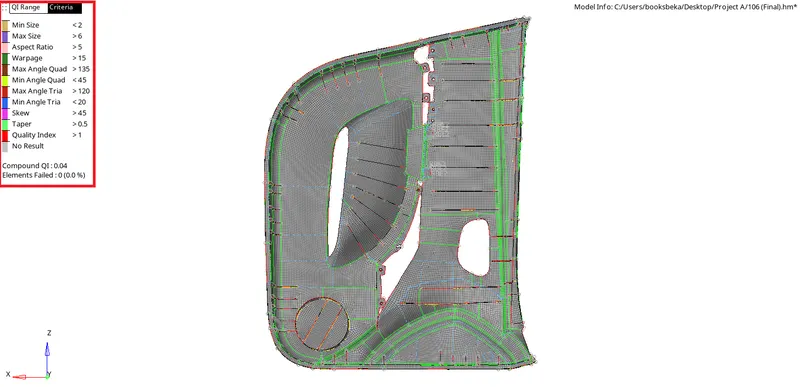
Result
We have acheived the following:-
i. Good Midsurface with:
a. No surface deformations
b. Well established connectivity between surfaces.
c. Complex features are captured manually.
ii. Good Mesh Flow with:
a. Zero Elements failing for quality
b. Features captured well.
c. No Free Edges in the entire component.
b. A Low Tria perecentage of : 2.1 %
Conclusion with learning Outcome
I learnt how to:
i. Choose the best option for extracting mid in order to save time in manual geometric cleanup.
ii. Choose the best combination of tools to perform manual cleanup on the mid surface.
iii. Perform a good mesh flow and choosing the best combination of tools to get rid of quality errors.
iv. Most importantly, trying different approaches for Meshing and cleanup inorder to save time and effort.