Study of different Interfaces using a Crush Tube
Comparing the different Cases for Crush Tube
Objective
To study the Interface of different cases and choose the best one.
The Interface is provided between Crush Tube and Rigid.
Study how the model reacts for different types of interfaces and geometry in each case.
Prerequisites
i. Interface
An interface is the Interaction of Parts when they come in contact with each other. This leads to the Penetration of the Slave nodes into the Master Segment.
The most common types of Interface are:
| Interface Type | Master | Slave | Gap | Stiffness | Usage |
| 7 | Node | Surface | Yes | Non-linear | General Node to Surface contact for any application |
| 11 | Line/edge | Line/edge | Yes | Non-linear | Edge to edge contact for any application |
| 24 | Node (or) surface | Surface | Shell | Linear | Applications are still new and specific. They occur mostly by self contact. |
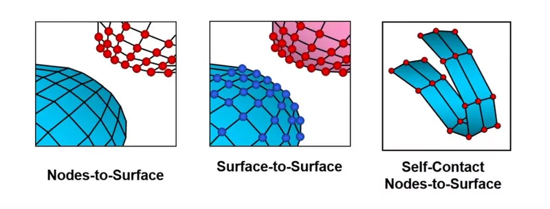
ii. Penalty method
a. Interfaces are governed by the penalty method.
b. When the parts come into contact, the slave node tries to penetrate the mid surface.
c. The solver introduces a 1D Spring element once the slave node penetrates the gap (T/2).
d. The stiffness of the spring is automatically computed according to the material and property of Master and Slave.
e. The Stiffness determines the Timestep i.e.
Timestep `propto`1/stiffness
Procedure
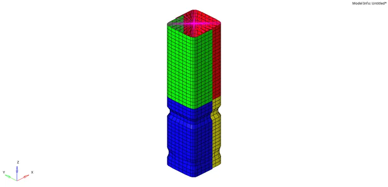
Step 1: Import the starter file
Import > Solver Deck > FIRST_RUN_0000.rad (select) > Import
The starter file is in ASCII (American Standard Code for Information Interchange) format and contains model information such as:
i. Nodes
ii. Load Conditions
iii. Velocity
iv. Boundary Conditions, etc.
[Note: The starter file should always end with 0000.rad. After changing the parameters (Eg. Velocity) and running the next simulation, the file becomes FIRST_NAME_0001.rad and so on.]
Step 2: Edit the Engine File and run the simulation
2.1 Edit the Engine File
Model Browser > Control Cards > Select and Edit
i. The engine File is in ASCII (American Standard Code for Information Interchange) format and stores Run control data such as Time History and Animation frequency, etc.
ii. We can edit the Engine file from the Control cards themselves.
2.2 Conduct the Analysis
Analysis > Radioss > Input File : (File Location) > Hit Radioss
i. The input file is the same Started file (contains model information) that we had just imported.
ii. The animation video along with the frames will be saved in the same folder where the starter file exists.
2.3 Review the Simulation
i. We have to import the animation file in Hyperview first:
Hyperview > Load File > FIRST_RUN. h3d > Apply
ii. From the simulation, we can review how the impact force acts and causes deformation and point of rupture on the model.
2.4 Case Setup
[Note: Follow the steps 2.1-2.3 to set up each case.]
We are going to compare cases based on 2 criteria:
i. With respect to Change in Interface parameters [Case 1,2 & 3].
ii. With respect to Change in Geometry [Case 4, 5 & 6].
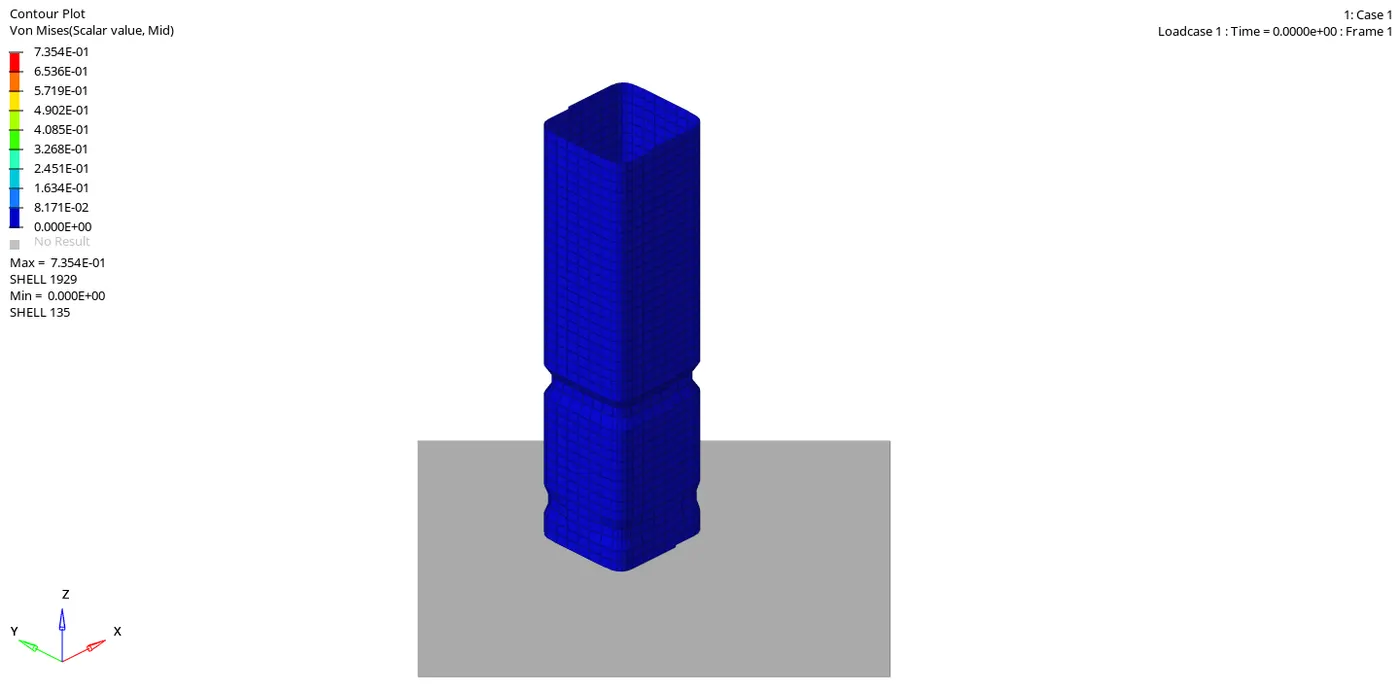
Case 1 (Default conditions)
Interface
Case 1 is set to the following parameters for Type 7 Interface:
| Control Card | Description |
| `Iunderset(gap`=0 | Constant Gap |
| `Gap underset(min` = 1.0 | In case `Iunderset(gap` fails, `Gap underset(min` is used to avoid penetration. |
| `I underset(stf` = 4 | Initial Contact stiffness |
| `St underset (min` = 1 | Minimum stiffness, to avoid Timestep error |
| `I underset (DEL` = 0 | Decides what to do with the slave and master nodes associated with the failed/deleted elements. |
| Inacti = 0 | Checks for Penetration before the crash |
| `I underset(FORM` = 2 | Friction formulation during contact (results in bigger timestep) |
Boundary Conditions
| Part | Degrees of Freedom |
| Rigid Body | Z-axis (Translation only) |
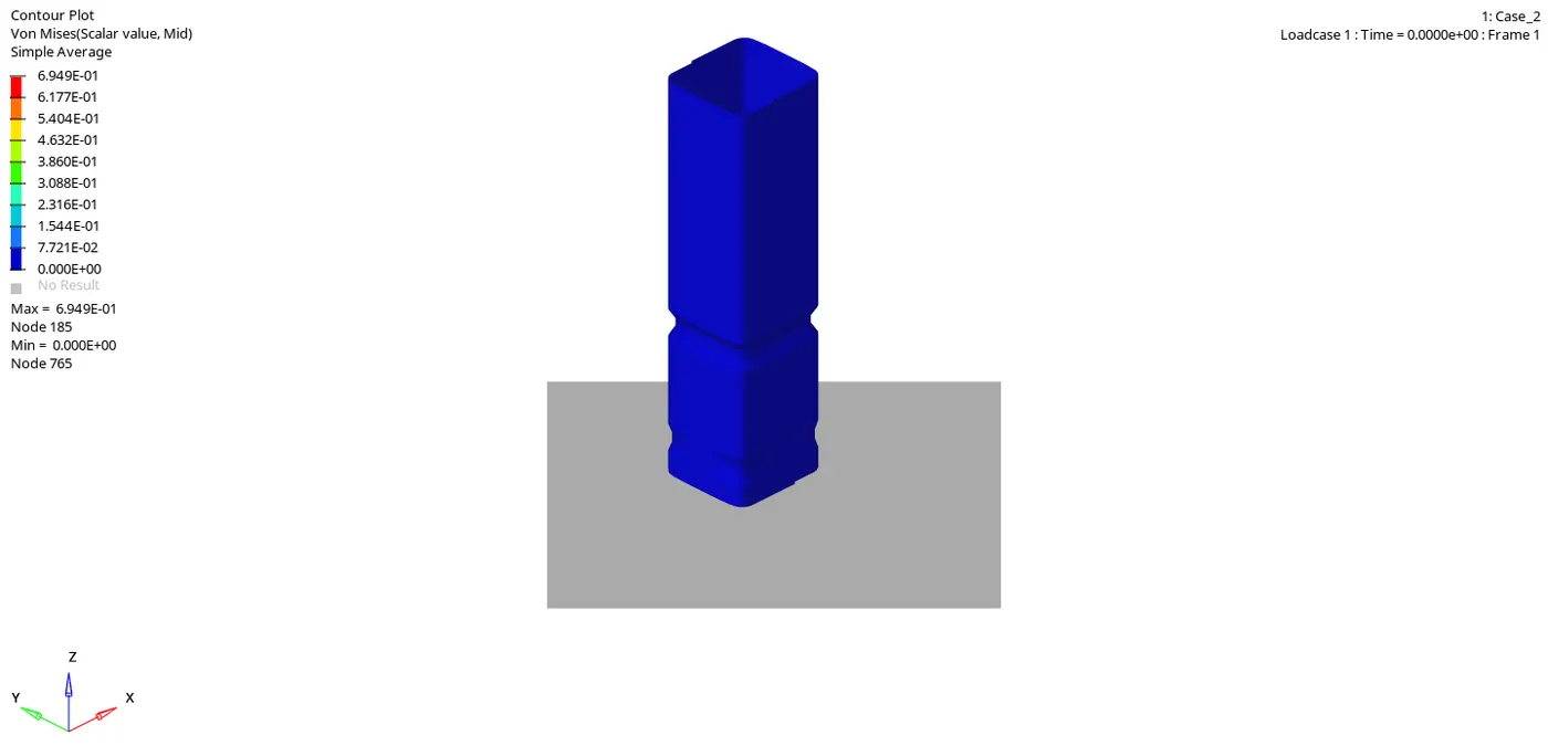
Case 2
| Changes | Description |
| Inacti = 6 | The Gap is reduced and removes Penetration error. Further Gap scaling is done to a factor of 0.8 |
Case 3
Case 3 is set to the default parameters for Type 11 Interface:
| Control Card | Description |
| `Iunderset(gap`=0 | Constant Gap |
| `Gap underset(min` = 0.0 | In case `Iunderset(gap` fails, `Gap underset(min` is used to avoid penetration. |
| `I underset(stf` = 5 | Initial Contact stiffness |
| `St underset (min` = 0.0 | Minimum stiffness, to avoid Timestep error |
| `I underset (DEL` = 0 | Decides what to do with the slave and master nodes associated with the failed/deleted elements. |
| Inacti = 0 | Checks for Penetration before the crash |
| `I underset(FORM` = 0 | Friction formulation during contact (results in bigger timestep) |
As everything is set to default, it is left to the solver to regulate the stiffness of the resistive force during contact which will affect the timestep of the simulation.
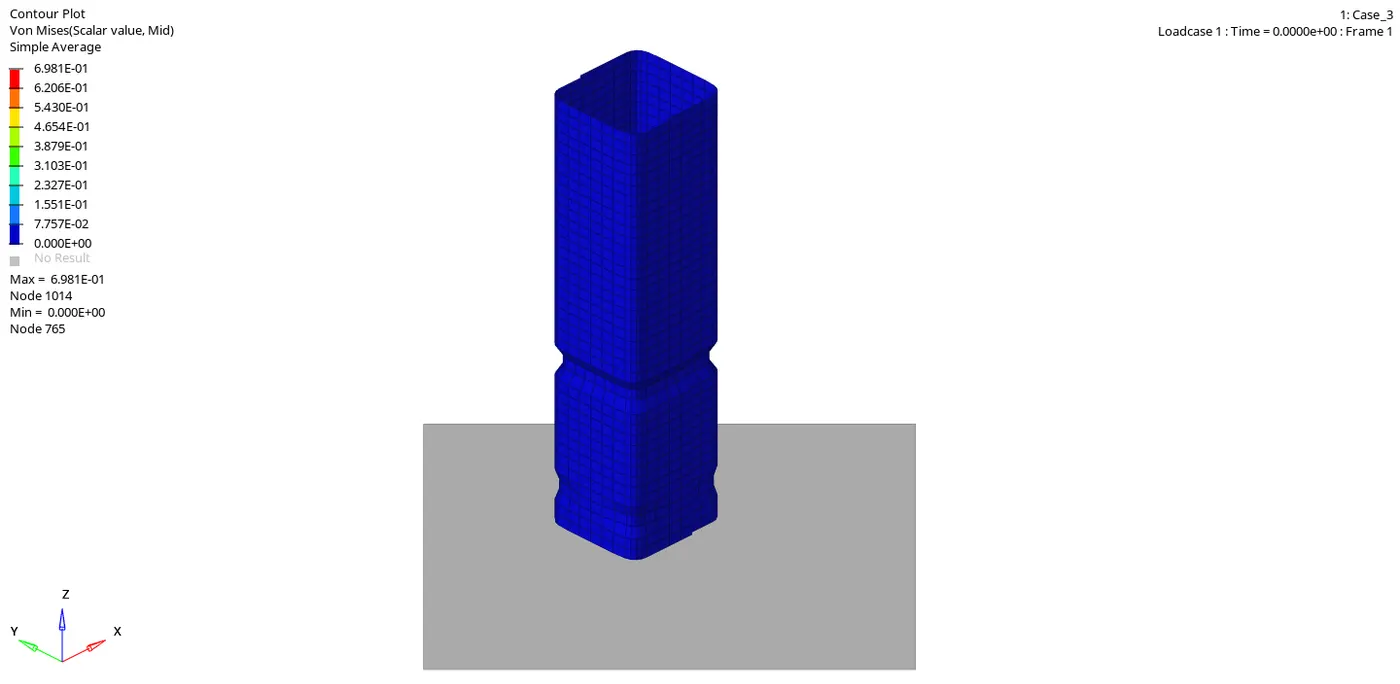
Case 4
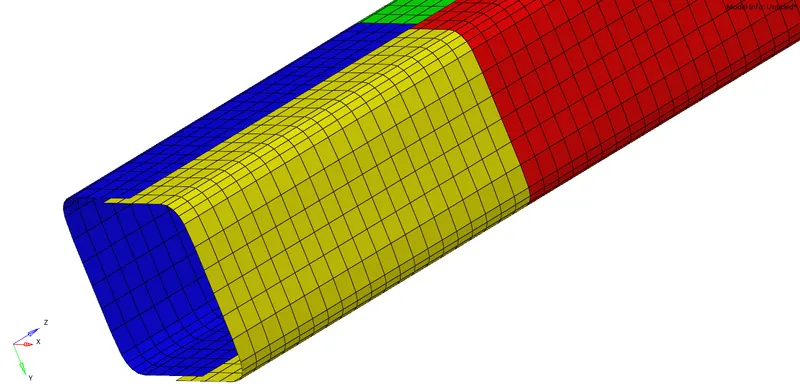
| Changes | Description |
| Align/Remove the Notches | The geometry is completely flat, which is going to affect the stiffness formulation during contact, and in turn the timestep. |
| Remove all DOFs | The Rigid body is free of all constraints. |
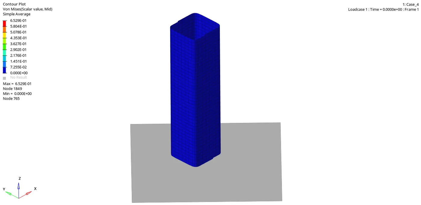
Case 5
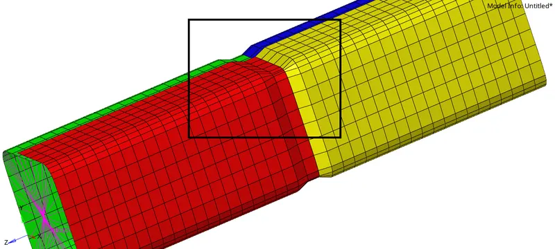
| Changes | Description |
| Create a Notch in the middle of the crush tube around the entire cross-section | Stiffness formulation will be different at this section of the geometry and we have to see how it affects the contact interface and the timestep. |
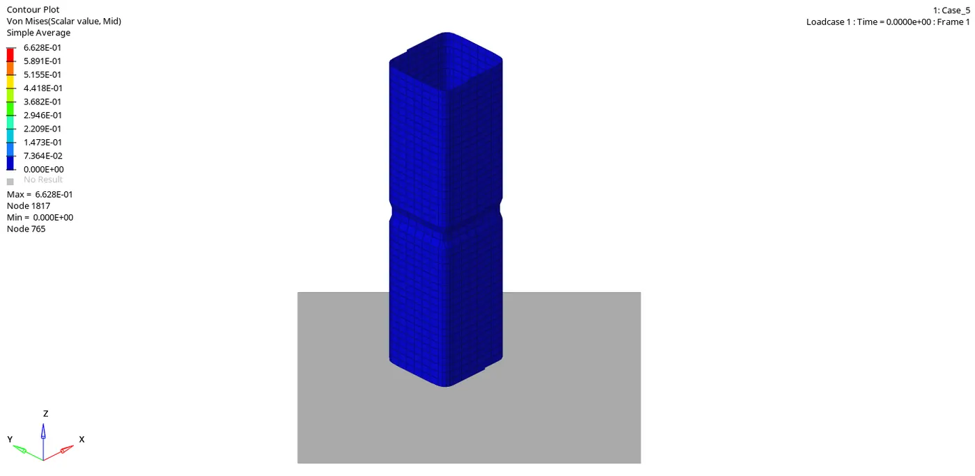
Case 6
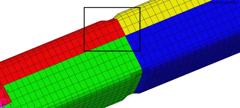
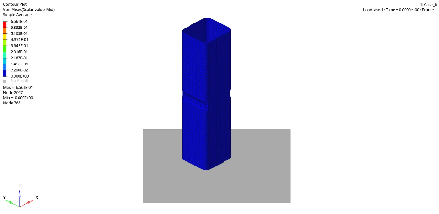
| Changes | Description |
| Create a new notch with nodes only from opposing 2 faces | Stiffness formulation will be different at this section of the geometry and we have to see how it affects the contact interface and the timestep. |
Results
[Note: Case 1 (Inacti = 0) and Case 2 (Inacti = 6) show equal results in all the plots indicating that there are no penetrations occurring in this particular crush-tube crash.]
| Rigid wall force and Global variables | Plots between Cases 1, 2 (Type 7) & 3 (Type 11) | Plots between cases 4, 5 & 6 | Result Description |
| Rigid wall force | 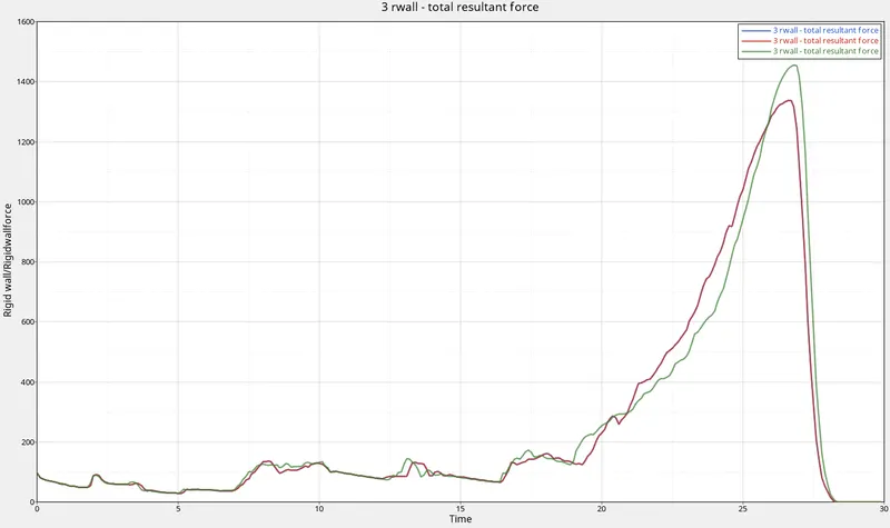 |
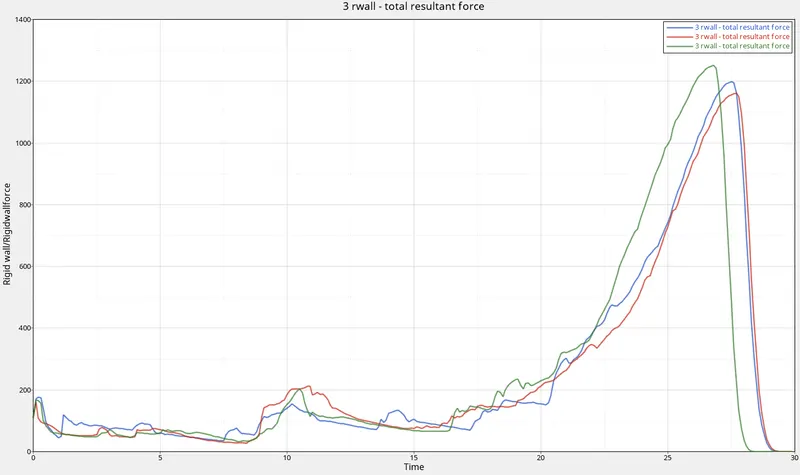 |
There are certain peaks in the curve, indicating more stiffness offered in the notch cross-sections of the geometry. The Rigid wall forces are maximum during plastic failure. Rigid wall forces in: Type 11 > Type 7 Case 6 > Case 4 > Case 5 |
| Internal energy | 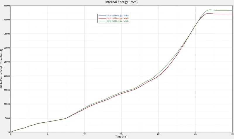 |
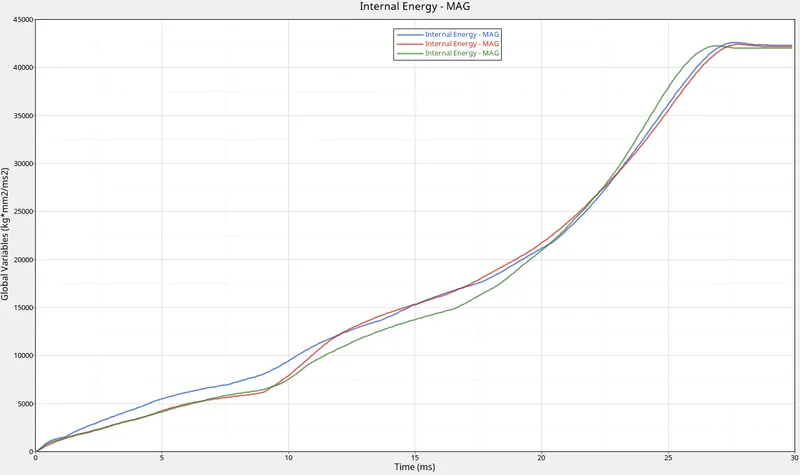 |
In each case, failure due to plastic strain occurs at slightly different intervals leading to different strain energies (area under the curve). Internal energy in: Type 11 > Type 7 Case 4 > Case 5 >Case 6 |
| Kinetic energy | 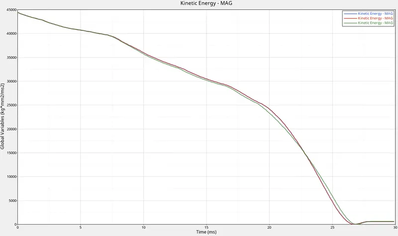 |
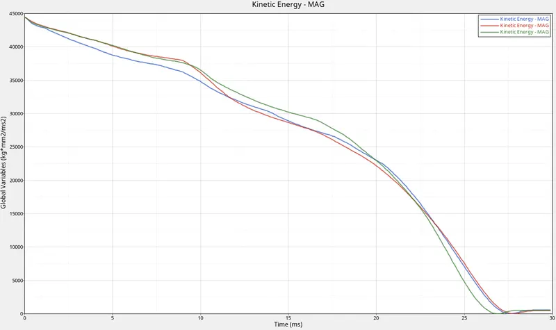 |
As it is being crushed, there is no space for the elements to move, motion (by velocity) is restricted leading to a loss in Kinetic energy. KE is almost similar in the 3 cases and change in geometry did not affect it. Type 7 ~ Type 11 Case 4 ~ Case 5 ~ Case 6 |
| Contact energy | 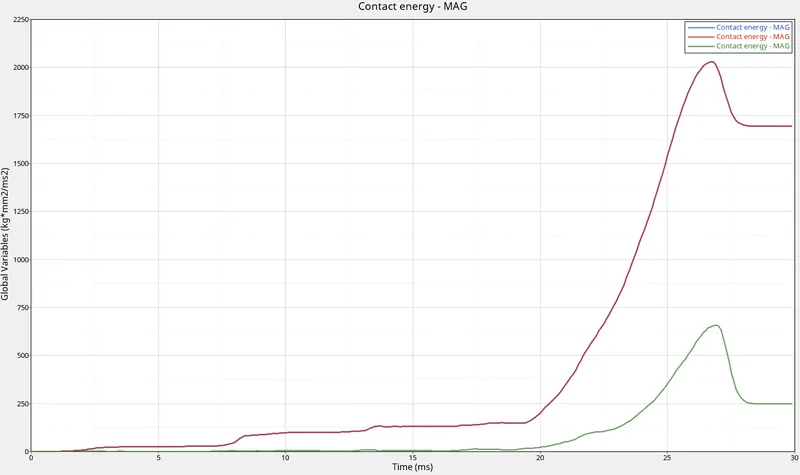 |
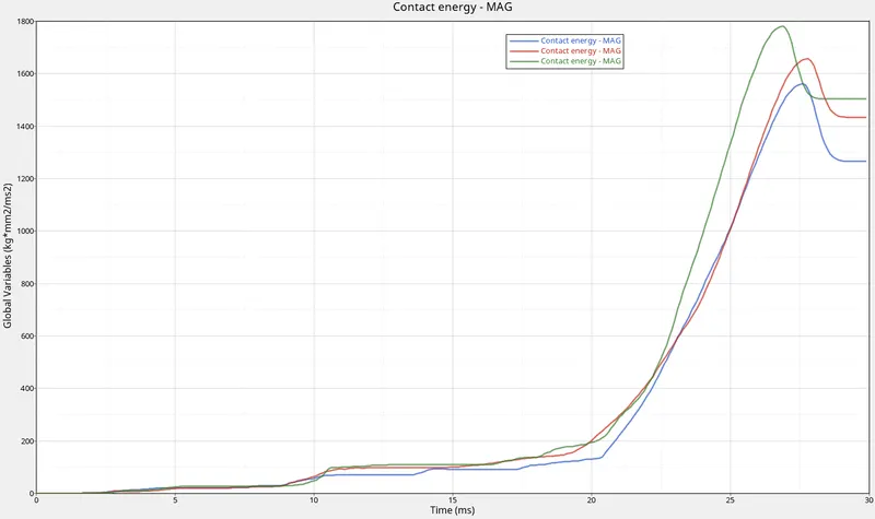 |
Contact forces are maximum at the point of plastic failure. Could be due to the fact that there is more contact as the element doesn't offer much stiffness at this point. Contact Energy in: Type 7 > Type 11 Case 6 > Case 5 > Case 4 |
| Hourglass energy | 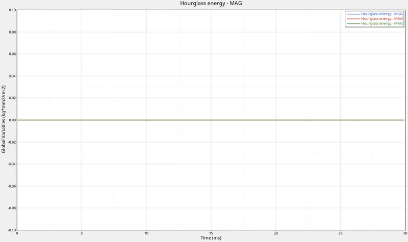 |
|
Hourglass is taken care of and won't cause Energy error. Case 1 = case 2 = Case 3 Case 4 = Case 5 = Case 6 |
| Total energy | 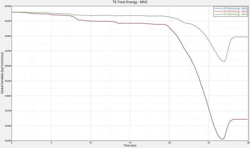 |
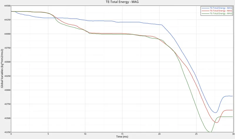 |
The Resistive forces (offered by the Stiffness of the element) gradually decreases up to the elastic limit and then decreases rapidly in the plastic region. Beyond this point too, the strain is occurring without any resistance therefore, there is a small hike in the Total Energy until Fracture. Total Energy in: Type 11 > Type 7 Case 4 > Case 5 > Case 6 |
Conclusion for the Crush Tube test
The type 7 interface proved to be the better choice because:
i. It had lower Rigid wall forces and Internal Energy indicating higher stiffness offered during Contact.
ii. The contact Energy was higher in case & which simulates a real-time model when being crushed.
iii. A significant amount of total energy is lost in the system (in type 7 contact) during plastic failure, which should be as expected.
In the geometric comparison of the Crush tube model, model 5 proved to show better results because:
i. The Notch in the middle helped the deformation to progress from that section so the deformation is well distributed across the length of the crush tube.
ii. The absence of the notch in case 4 caused it to deform progressively at the contact interface and, the rate of deformation and rigid wall forces were higher than case 5 (with notch).
iii. The nonuniformity of the cross-section in case 6 caused a significant increase in the Tangential forces leading giving us undesired results.
Bumper System
Objective
i. Manually Clean up the Geometry
ii. Generate a good Mesh flow on the surface.
iii. Connect the parts using 1D connections.
Procedure
Step 1: Importing
i. Since we are importing a CAD geometry, the format will be either of the 2 industrial accepted standards:
a. STEP (Standard for the Exchange of Product data).
b. IGES (Initial Graphics exchange specification).
c. When selecting the file for import, be sure to check if it is .stp or .igs.
File > Import > Import Model > File type > Open File > Import File
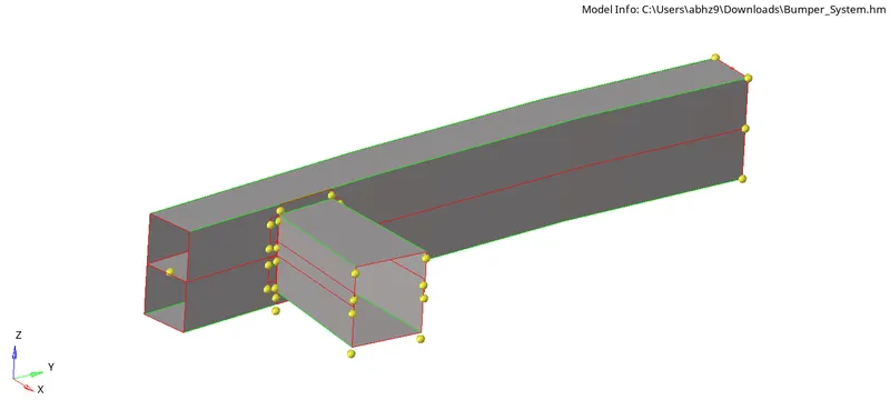
d. We only have to work on the geometry, so before inspection check for solids and delete if there are any.
Delete [F2] > Solids > Displayed > Delete Entity
[Note: We can also check for solids by switching it to TOPO mode. If there are solids, then the geometry will be highlighted in green.]
Step 2: Inspection
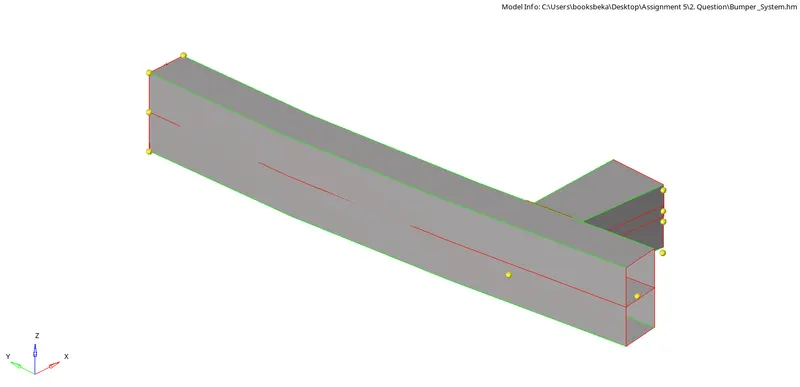
Check for Geometric Deformations
i. Surface deformations
ii. Free edges
iii. Unnecessary Connections (Extra points and lines)
iv. Connectivity error
Step 3: Manual Clean Up
Manual Clean up is done for the following reasons:
i. Generate a good mesh flow.
ii. Surface deformations.
iii. Connectivity errors.
iv. Making sure the features are captured properly.
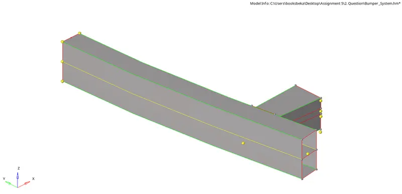
Fix the errors using the Tools in the quick edit panel:
i. Use the toggle option to connect the free edges.
ii. Fix for Connectivity issues using Add/ Remove point and Replace point option.

Step 4: Meshing
4.1 Rules to be followed for Meshing
Before beginning to Mesh, there are some certain rules to be followed regarding Tria Management, in order to generate a good mesh flow:
i. No Opposite Trias
ii. No Trias on edges (Especially Free Edges)
iii. No Trias on Corners
iv. Avoid Trias on Fillets
v. Avoid Rotating Quads
[Note: Trias are stiffer elements than Quads and therefore, if they are in the regions as mentioned above, the part is most likely to fail in those regions. Therefore, it is best to perform meshing by keeping those rules in mind.]
4.2 Begin Meshing on surfaces [F12]
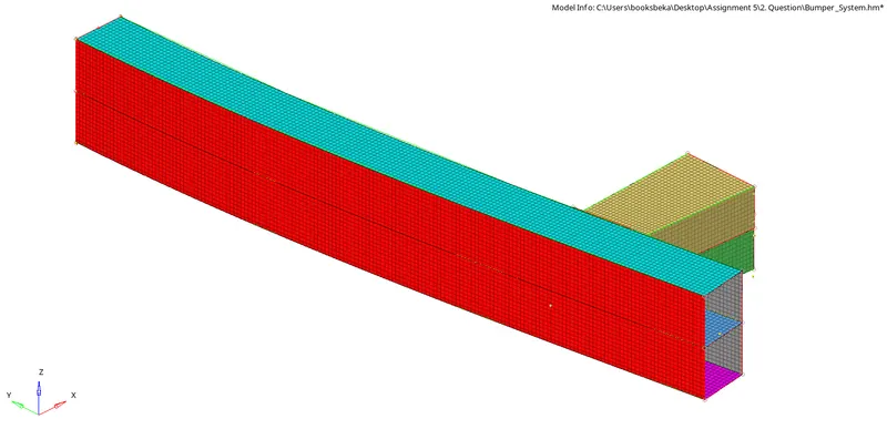
i. We can observe that all the faces are geometric, so we can go with Quads Mesh type.

2D > Auto Mesh > "Surfs" > Element size = 5mm > Mesh Type : Quads > Check for align and size > Mesh
ii. Don't forget to check for "Link opposite edges with AR <"
iii. Once we give for mesh, we can edit the mesh density by changing the number of nodes.
Step 5: Connections
i. As the Bumper component is a crucial part during a crash, we have to ensure that proper connections are established so that the sectional forces get transmitted to the next part.
ii. Connect the surfaces by using the 1D Weld option.
iii. The 1D connection is established between the node of one part and the node of another.
[Note: Make sure that all the weld connectors are realized (Green in Colour).]
Result
i. The Geometry was manually cleaned and free of errors.
ii. A good mesh flow was achieved using only Quad elements.
iii. Appropriate connections were made between the parts.
Learning Outcome
i. Overview of the type of interfaces and their applications.
ii. Causes for Penetration
iii. How the Penalty method is used in governing the Penetration.
iv. The Interface parameters that are used during the interface.
v. How the solver computes for stiffness formulation, penetration, and element deformation during an interface.