Generative Shape Design of Door Arm Rest
OBJECTIVE
Conduct a Draft Analysis for the Door Arm Rest Model by determining the appropriate Tooling Axis and check if all the features are above the Nominal Draft angle (3 degrees).
PROCEDURE
STEP 1: CHECK CONNECTIVITY
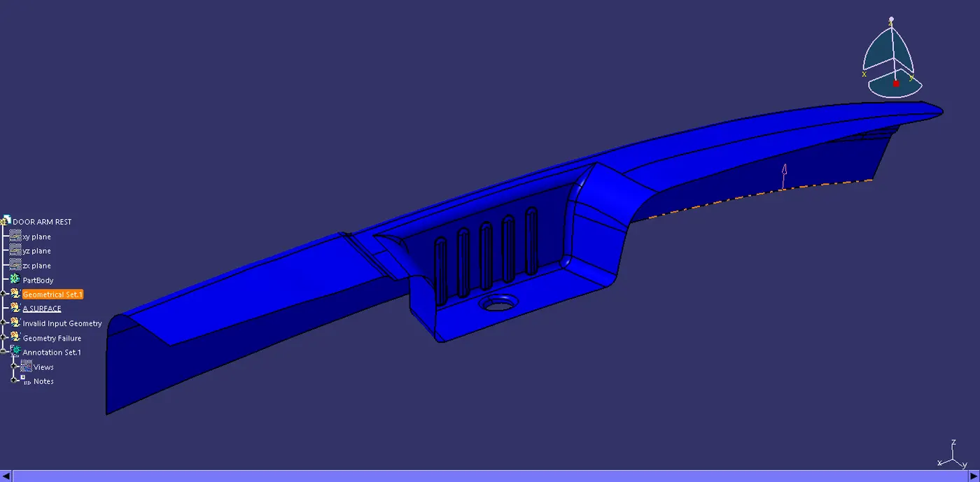
We have to ensure that the Class A Surface is connected as one single profile. We can do that with 2 options:
| Visually | Using the Join option. This option is efficient but not effective. |
| Manually | Extracting the Boundary of the Class A surface. This option confirms better. |
STEP 2: FIND THE TOOLING AXIS
- Tooling Axis is the direction in which the Mold(Core-Cavity) travels perpendicular to the parting surface/line.
- Place the component on each plane (XY/YZ/ZX) and find the desirable tooling direction.
[Note: The plausible tooling axis is perpendicular to a Hole or large flat surface so look for those features when selecting.]
- So we need to create a midpoint on the plane perpendicular to the tooling axis.
| Holes | Use Multiple extracts to get the Boundary and define a midpoint using the "Curve/Circle" option. |
| Flat Surfaces | Extract the surface and then create a mid-point using the "On Surface" option. |
- Now, introduce an Axis system at the Midpoint. This will act as a reference coordinate system.
STEP 3: EXTRACT THE BOUNDARY FOR BISECTING THE TOOLING AXIS
- Intersect the respective plane with respect to the component.
- We get a First Angle projection of the component with respect to the direction of view.
- Analyze if each profile will pass the tooling.
- Note:
- Perpendicular lines always pass the draft analysis.
- Check the Fillet radius.
- Manually check for the Parallel(almost parallel) lines to ensure they have a positive draft angle.
STEP 4: DRAW THE TOOLING/DRAFTING AXIS
- Extend the almost parallel lines by drawing lines with a Point-Point definition.
- Bisect the lines with respect to the center point to get the "Dummy Tooling Axis"
- We can view the Tooling from 2 different planes (Front and Side view) so repeat the above procedure for the other plane.
- Finally, Bisect both the "Dummy Tooling Axis" with respect to the center point to get the Final Tooling Axis.
- Publish the tooling axis and the Class A surface so it becomes easy to access during future operations.
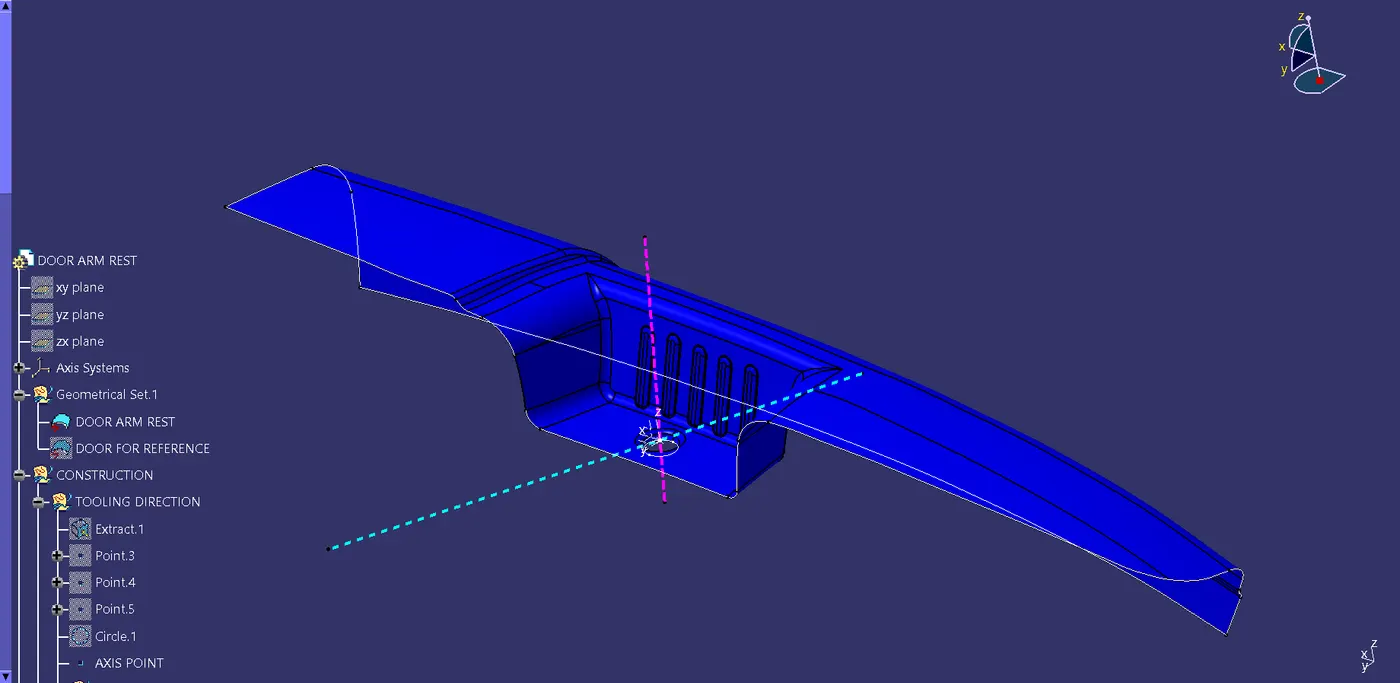
- Due to the complexity of the part, it needs a Side Core/ Lifter along with the main Core.
- Therefore, we have introduced a Side tooling using the bisecting method as well.
STEP 5: DRAFT ANALYSIS FOR CLASS A
Insert > Analysis > Feature Draft Analysis
Note: Ensure you have the Material view mode ON.
- Define the Draft direction using the "Compass" option.
- Drag the Axis system representation close to the model and align it along the tooling axis.
- "Lock" the Draft direction.
- Set the Colour scale
| Colour | Description | Value |
| Green | Core Side | Above 3 degrees |
| Blue | Parting Line | 0 degrees |
| Red | Cavity Side | Below 0 degrees |
| Method 1: Manual Selection | Method 2: Visual Selection |
|
|
Method 2 is more efficient as it gives us an overall result of the draft analysis without manually picking any feature.
STEP 5: B SURFACE CREATION
Note: Depending on the geometry, the extraction and offset of the fillets might generate non-uniform thickness. So it is advisable to extract only the flat surfaces and then apply fillets at the end of Class B formation.
Perform the following operations in the order:
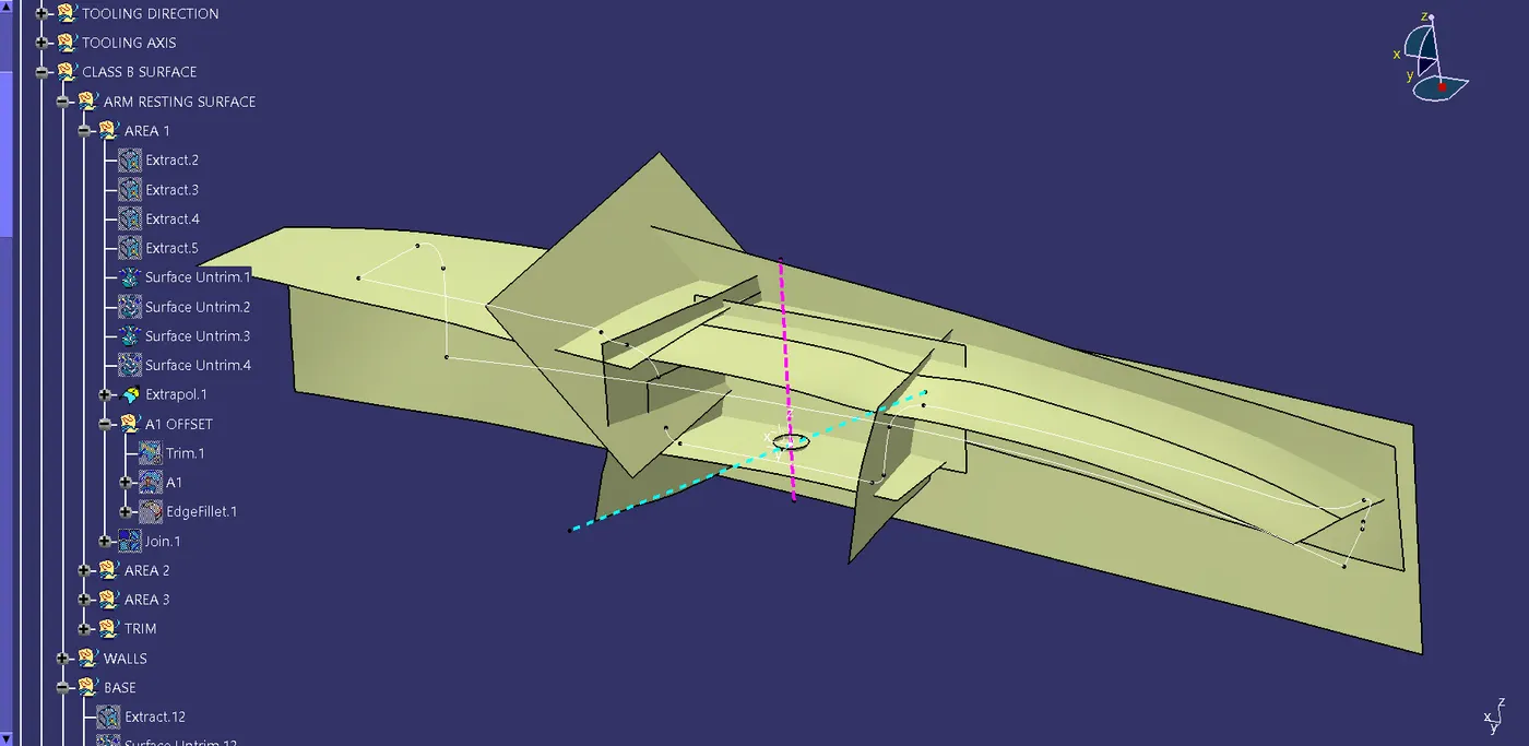
| EXTRACT | Choose the respective A surface and extract with no propagation option. |
| UNTRIM | The extracted surface will possess the specific trimmed. Untrim to get the basic geometry. |
| EXTRAPOLATE | The surfaces have to overlap each other in order to facilitate trimming therefore extrapolate it up to the required dimension. |
| TRIM | Trim the surfaces according to the required geometry. |
| OFFSET | Now, Offset the Trimmed geometry by the value of the thickness of the component. This Offset is our B Surface. |
| FILLET |
|
| Extracted, Untrimmed and Extrapolated surfaces | Trimmed B surface with Fillet |
 |
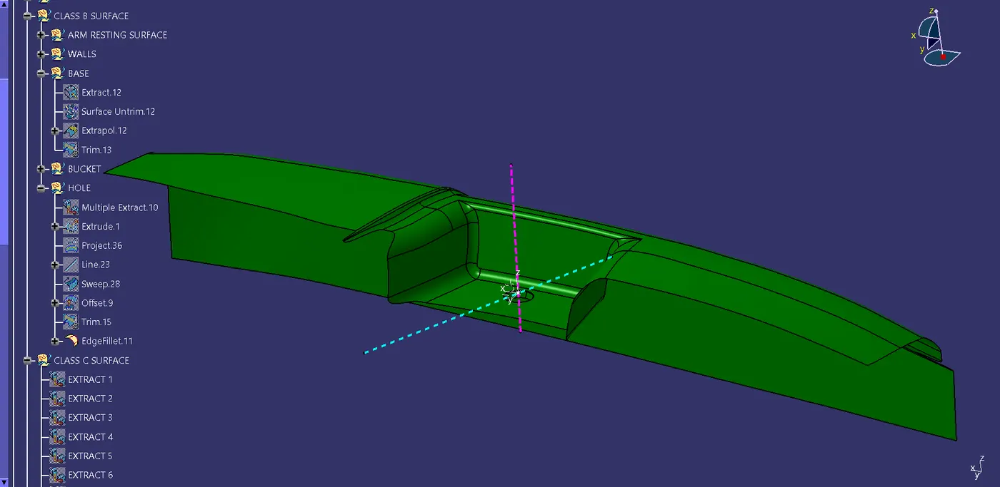 |
Note: The fillet radius of the Class B offset is altered to maintain the uniform thickness throughout the geometry.
| Offset direction | Fillet Radius |
| Inward | Initial Radius - Thickness |
| Outward | initial Radius + Thickness |
STEP 6: C SURFACE CREATION
C surface is the part of the geometry that connects Class A with B surface.
Rules to be followed. for C surface creation:
- A minimum draft of 3 degrees should be provided to facilitate the Ejection of the Molded component.
- The parting line should be on the B surface. This means that the draft should sweep outwards, from the C surface.
Perform the following operations in the order:
| MULTIPLE EXTRACT | Extract only the Boundary by Tangential selection. | |
| CURVE SMOOTH | We need minimum Parting lines as possibles, so smoothen the extracted boundary. | |
| SWEEP |
The C surface is swept with the Line option along the Drafting Angle Direction.
|
|
| MULTI-SECTIONS SURFACE |
In places like Fillets where the Sweep option doesn't work, we can fill in the gap using MSS.
|
|
| EXTRAPOLATE |
The Sweeps at the edges need to overlap in |
|
| JOIN | For our future reference, we can Join all the C surface sweeps as one single entity. | 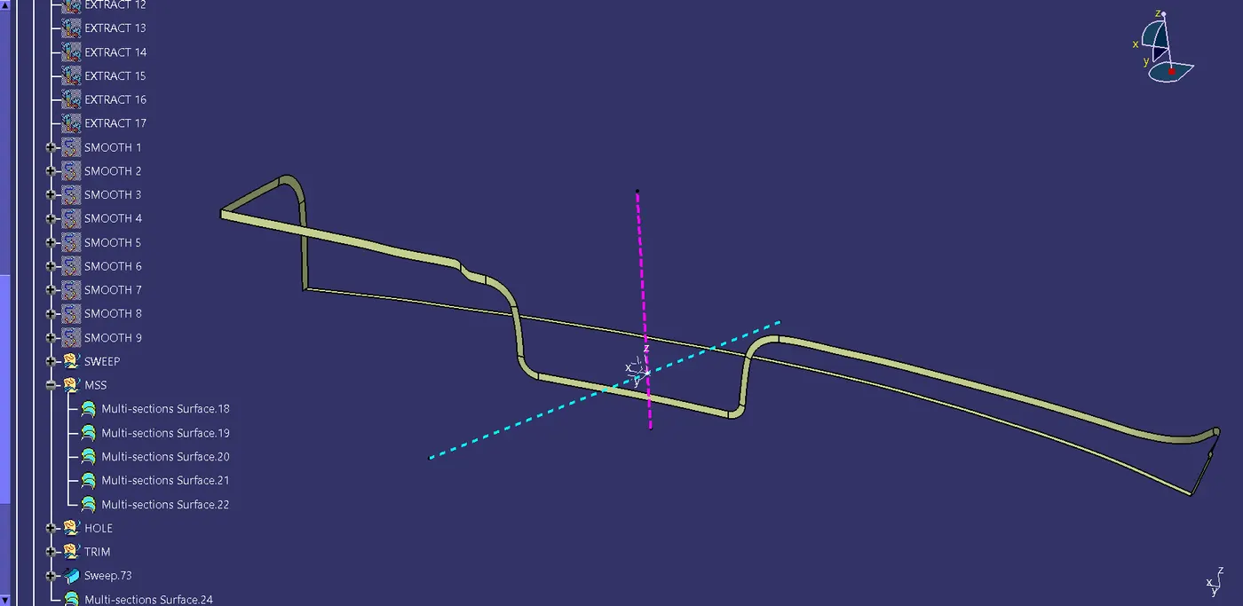 |
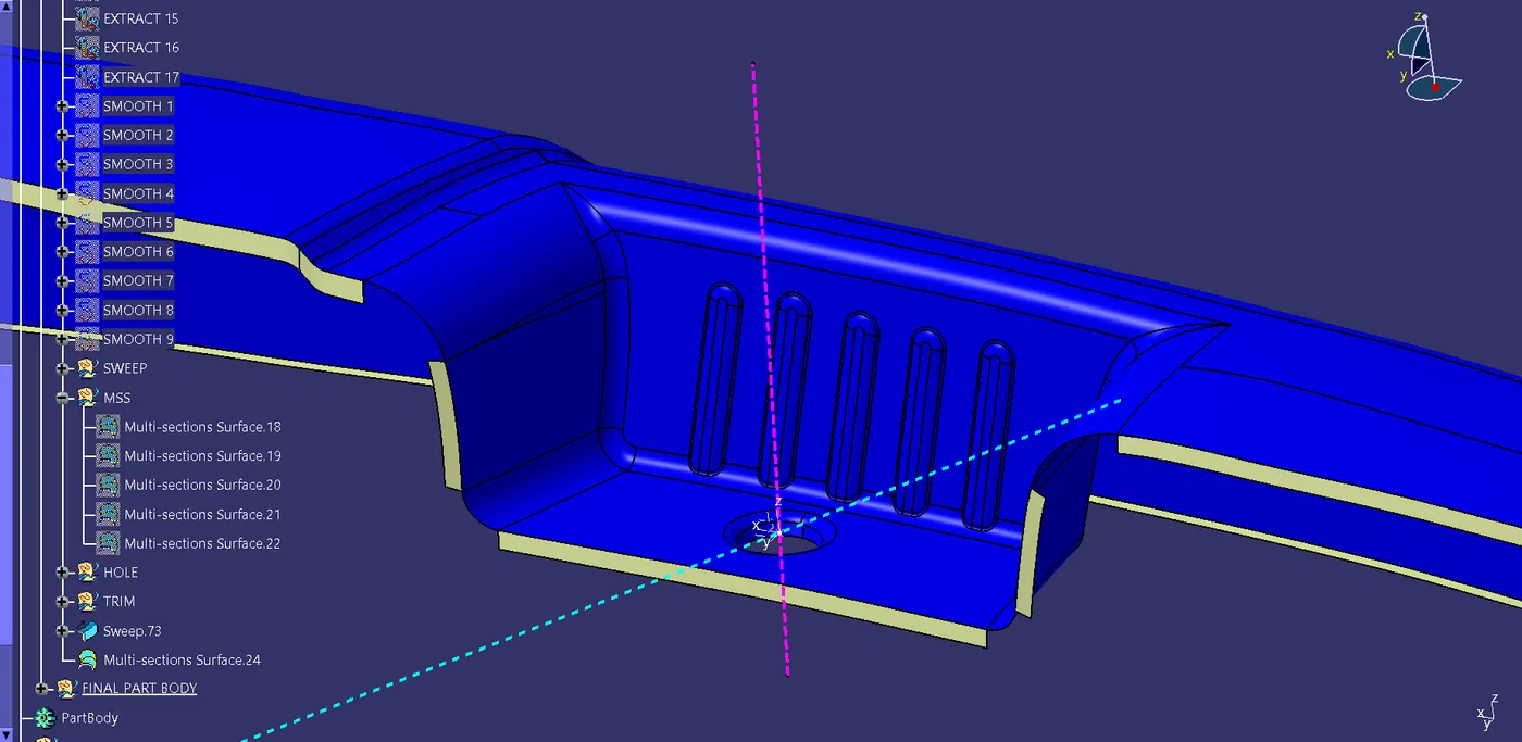
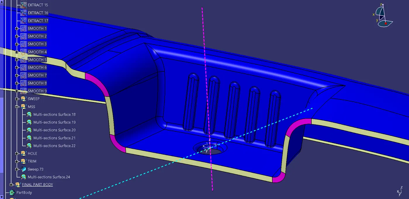
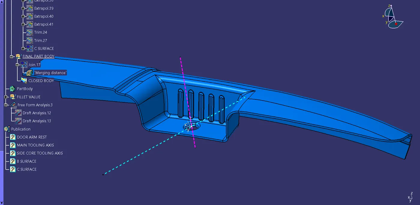
STEP 7: CLOSED SURFACE
- First Trim/Join Class A with Class C.
- Then Trim with Class B and keep the respective surfaces.
| Surfaces to Trim | Closed Surface |
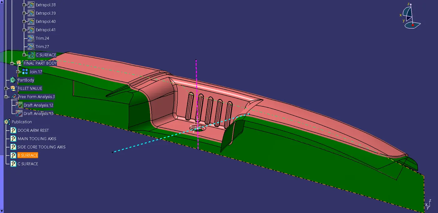 |
 |
STEP 9: SOLID BODY
- Switch to Part Workbench.
- Define the part body.
- Select the closed surface trim to fill it with volume.
- Now we have a solid body with a certain volume and density (depending on the material we give).
STEP 10: FINAL DRAFT ANALYSIS
All the 3 class surfaces must pass in this analysis.
Insert > Analysis > Feature Draft Analysis
Note: Ensure you have the Material view mode ON.
- Define the Draft direction using the "Compass" option.
- Drag the Axis system representation close to the model and align it along the tooling axis.
- "Lock" the Draft direction.
- Set the Colour scale
| Colour | Description | Value |
| Green | Core Side | Above 3 degrees |
| Blue | Parting Line | 0 degrees |
| Red | Cavity Side | Below 0 degrees |
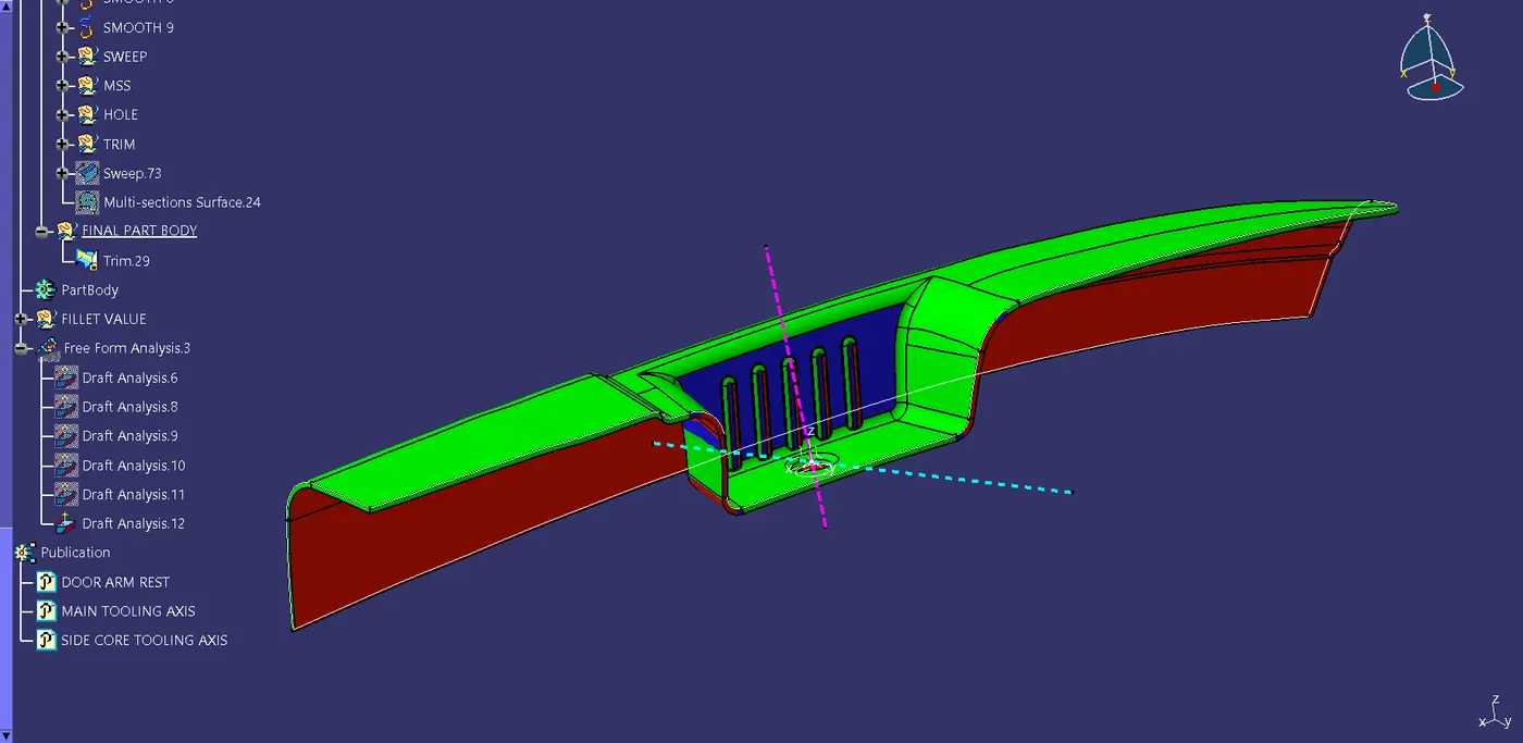
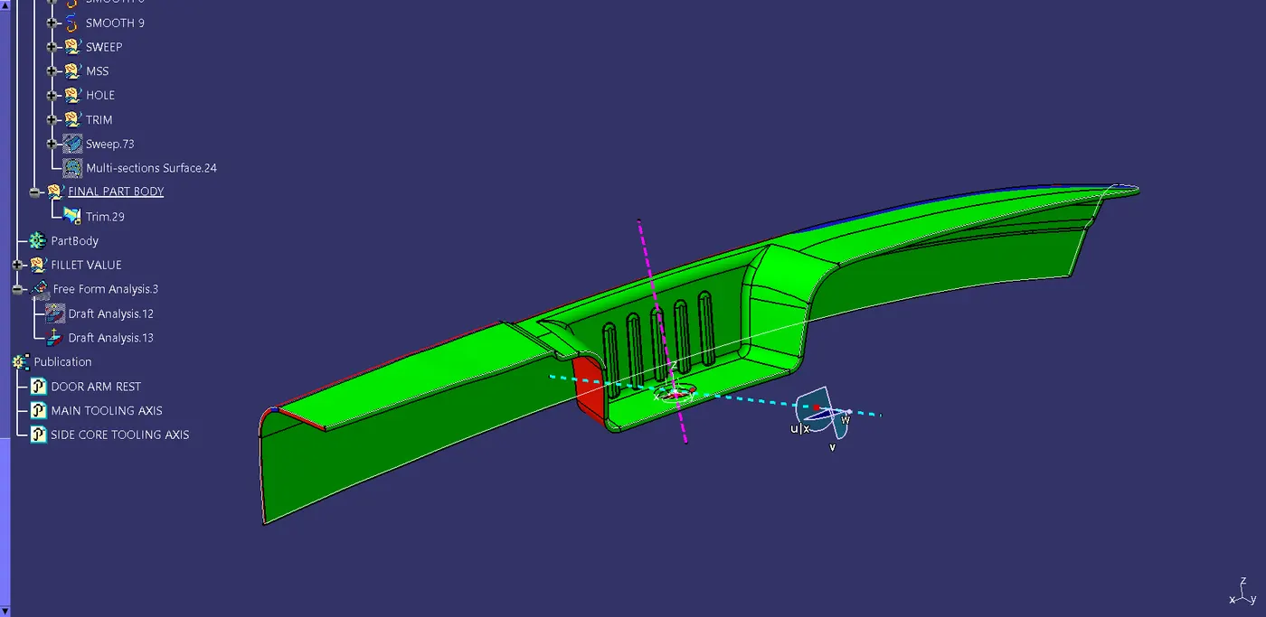
- Place the Analysis Tool (Arrow Icon) anywhere on the model and review the colours on the feature.
- If any feature (especially C surface) is showing Blue/Red then choose the same option again (It will switch to Analysis under Running point) and place on the respective feature to review the deviation of the sweep angle from the Tooling Axis.
| Some surfaces failing for the Main tooling: | The failed surfaces are passed by the Side tooling: |
 |
 |
RESULT
We get the following Desirable Outcome:
| Green |
|
| Red |
|
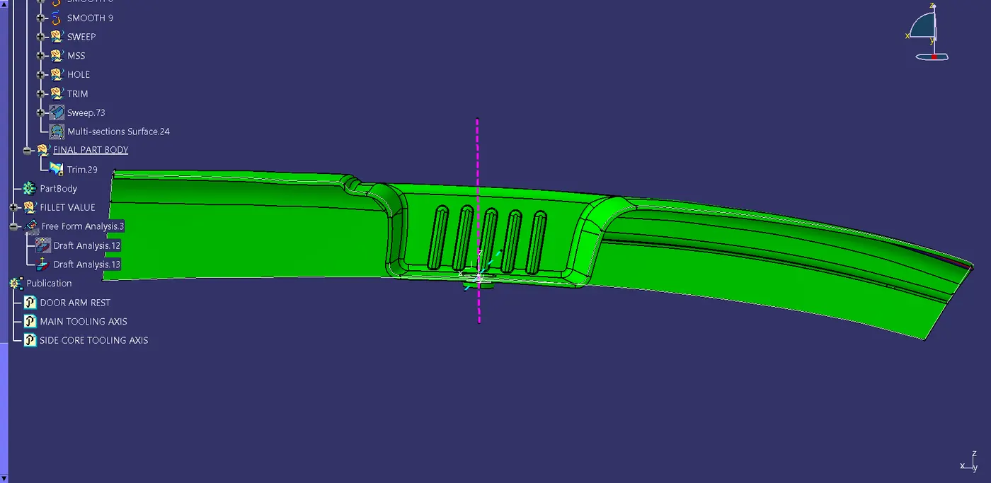
- Since we have done the Initial Analysis for Class A, the only area for drafting error might occur in Class C.
- If Class C shows Red/Blue in colour, then the draft given is not right and we have to edit the sweep angle to get the draft above 3 degrees.
- Rectify the error until we get the Desired output and submit the final model.