BiW Hood with N CAP regulations
OBJECTIVE
To create an Opening body panel (i.e. Hood) that covers the Engine compartment while passing in:
- Frontal Crash Test
- Pedestrian safety
- Dissipate forces outside the car body.
DESIGN PRINCIPLES
| Sl. No. | Design Considerations | Description |
| 1. | NVH |
|
| 2. | Hoodstay Mounting |
|
| 3. | Latch and Striker point |
|
| 4. | Hinge Axis |
|
| 5. | Deformable Bracket |
|
| 6. | Euro N-CAP Assessment |
|
| 7. | Pedestrian Rating |
|
PROCEDURE
STEP 1: PRELIMINARY STUDY
Before working on the Hood, we need to ensure that the Hood is feasible for the market. We study for:
| Sl. No. | Criteria | Description | Visual Representation | ||||
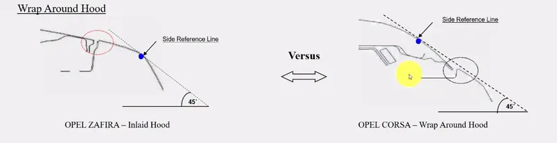
| 1. | Type of Hood |
We decide on the type of Hood for a better pedestrian rating.
|
|
||||
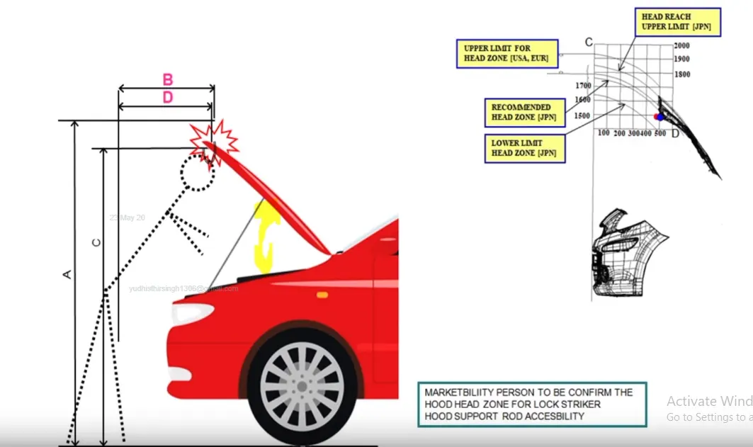
| 2. | Headzone for Locker Striker |
Hood Opening Angle = 55-68 degrees
|
|
||||
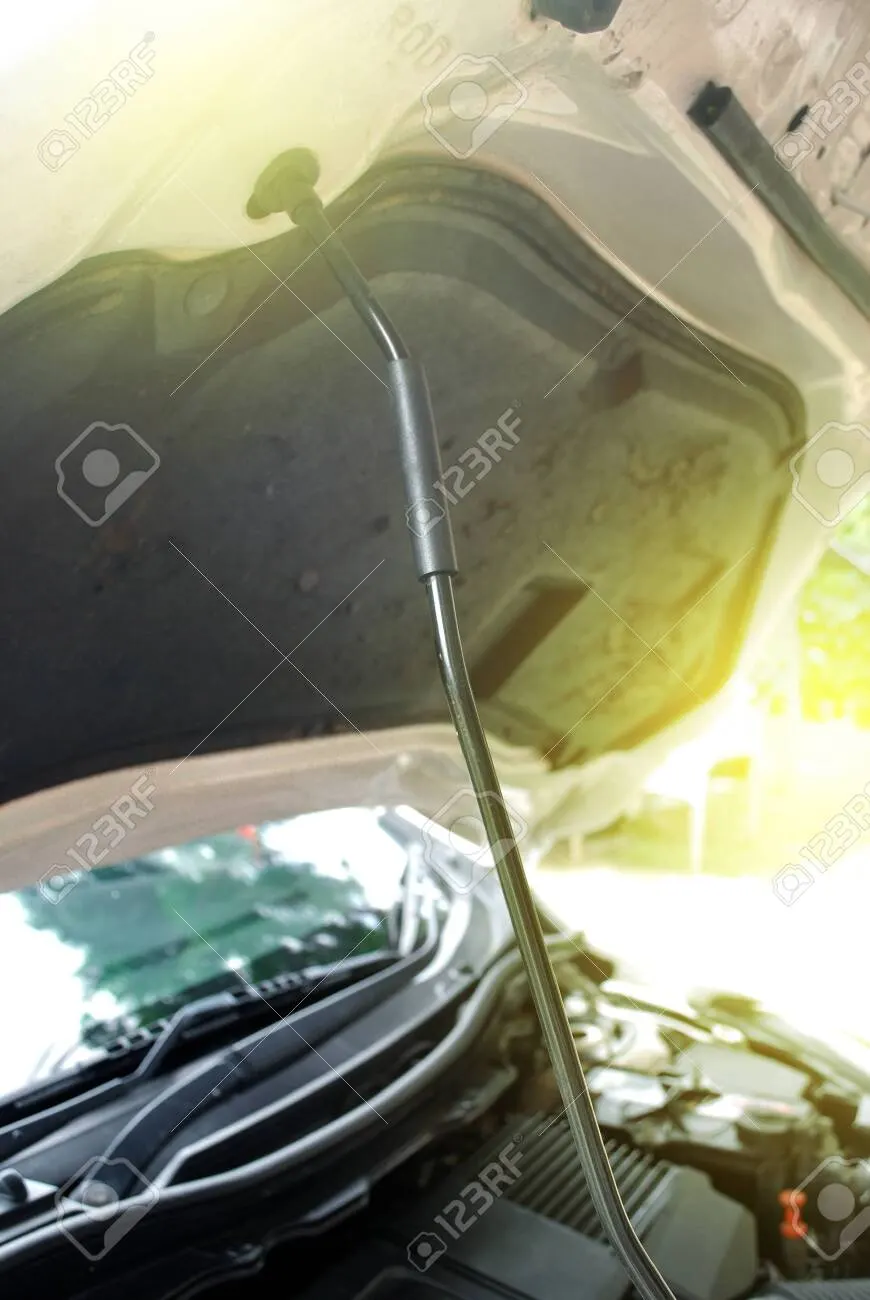
| 3. | Hood Balancer |
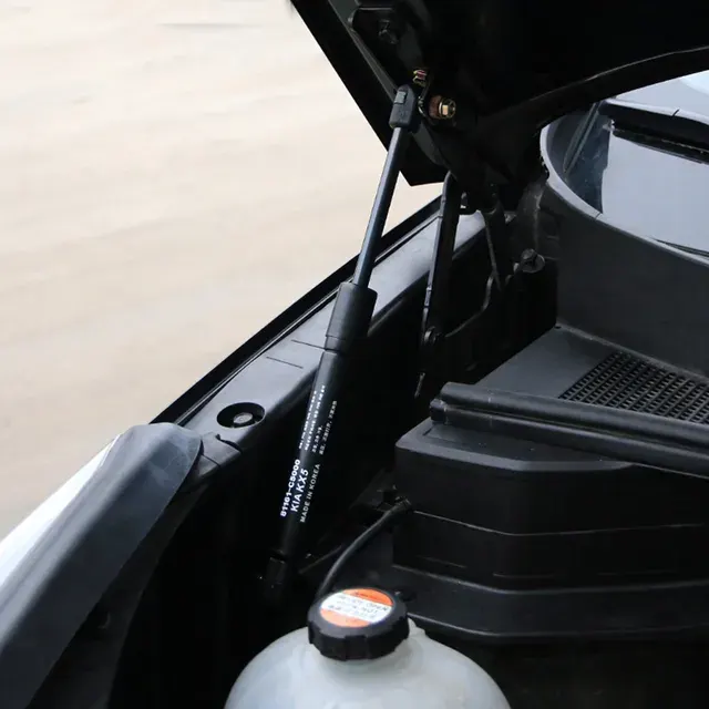
A mechanism that holds the hood open. Support Rod
Gas Stay
|
|
||||
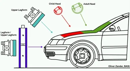
| 4. | Pedestrian Head Impact Zone |
After getting skin data, we'll refer to:
We plot the regions for the Adult and Child Head Impact zone. |
|||||
| 5. | Predesign |
|
 |
STEP 2: INPUT
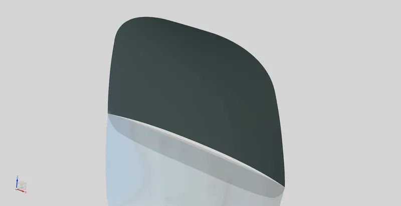
- We get the Class A surface with predefined edges from the Styling Team.
- We get a Master Section as well, which is a predefined sketch that is adaptable to different situations.
- As Design Engineer, we check for the initial feasibility and whether the part has to be raised/lowered.
Note: We don't have reference data like the engine compartment, we can go ahead with designing the engineering features.
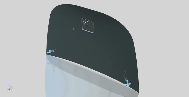
- Add/Create the parts (Input Class A, Hinge and Striker) to the new assembly:
- Hood Inner Panel (Create Part)
- Hood Outer Panel (Add Part)
- Hinge Assembly (Add Assembly)
- Striker (Add Part)
STEP 3: MEETING THE SAFETY REQUIREMENTS
| Requirements | Problem | Solution | ||
| Pedestrian Safety | If the Hood is too rigid then the pedestrian will suffer from a severe head impact during a collision. |
|
||
| Passenger Safety |
During a frontal crash, the stresses travel straight into the cabin. |
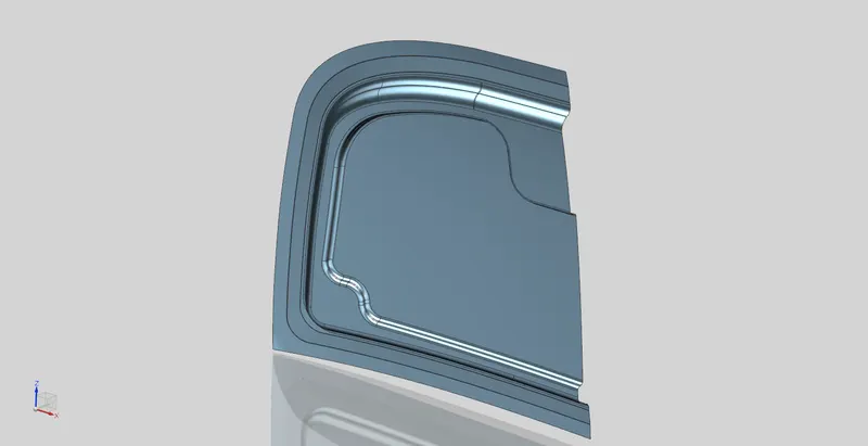
Create Emboss along Y or V directions for the forces to be distributed sideways and onto the Crumple zone, that is,
|
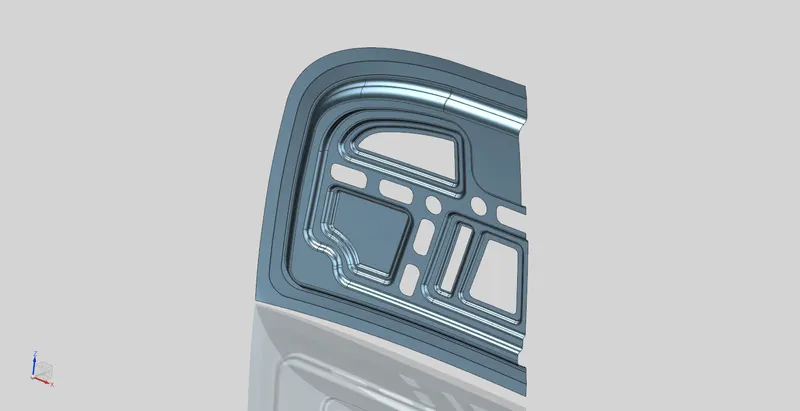
- Offset class A surface by 25 mm to meet the Pedestrian safety requirements.
- Provide a 40mm width for the offset and open the part by 45 degrees to provide Deep Drawing conditions.
- Take another offset of 10-15 mm and further to 5-6mm.
- These Offsets create Emboss that satisfies 2 applications:
- Removing material and making it lighter.
- Adding strength by functioning as a reinforcement.
Design Rules to be followed to meet Manufacturing standards:
| Draft Angle |
|
| Emboss spacing/clearance |
|
| Clearance for Material removal |
|
Functions performed for creating the Emboss on the Inner Panel:
| Offset surface |
Note: The Offset dimension is limited up to the Radius of the surface (if curved). But if the surface is complex then it gets distorted from a far distance, well within the limit. |
| Offset curve on surface |
Note: Ensure the curve gets,
|
| Trim sheet |
|
| Through curves |
|
| Law extension |
|
| Emboss |
|
| Face blend |
|
| Edge blend |
|
| Sketch Tools |
|
| Project Curve |
Note: We cannot sketch on a curved surface. Therefore, we sketch on a datum plane and project it onto the respective surface to get an accurate section of the sketch. |
STEP 4: HOOD OPENING (ABOUT HINGE AXIS)
| Conditions | Description |
| Opening angle | 55-68 degrees |
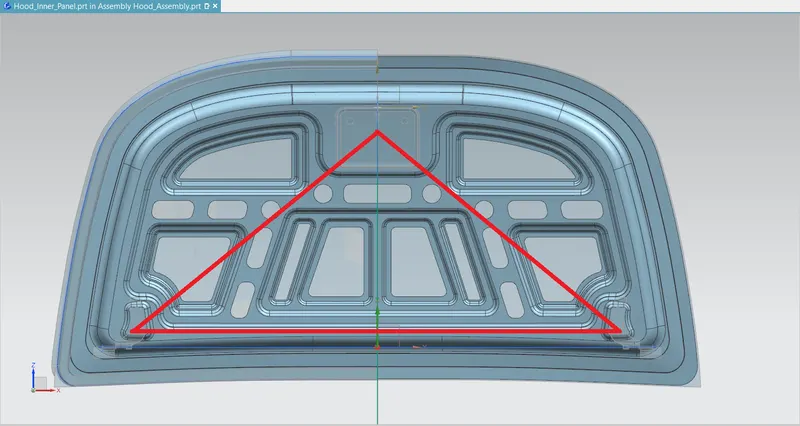
| Hood Balancer | Close to the Centre of Gravity (Triangular region joining Hinge Axis and Striker Locking point) . |
Design Principle to be followed:
The Hinge position is correct when the Striker is exactly perpendicular to the trajectory at the local region.
- Take the Opening position of the Hood and hold the Hinges tentatively, along a straight line.
- The straight line is the Hinge axis. Now we have 3 inputs:
- Hinge axis point (Centre point of Hinge axis)
- Master Section (Predefined)
- The concept from the previous vehicle (We don't have so we go with our own design)
- From the input, we get a predefined Triangular area that is exactly over the Centre of Gravity, and we validate if it is right.
- The Height of the Triangle is determined by the radius of the circle drawn perpendicular to the Hinge axis.
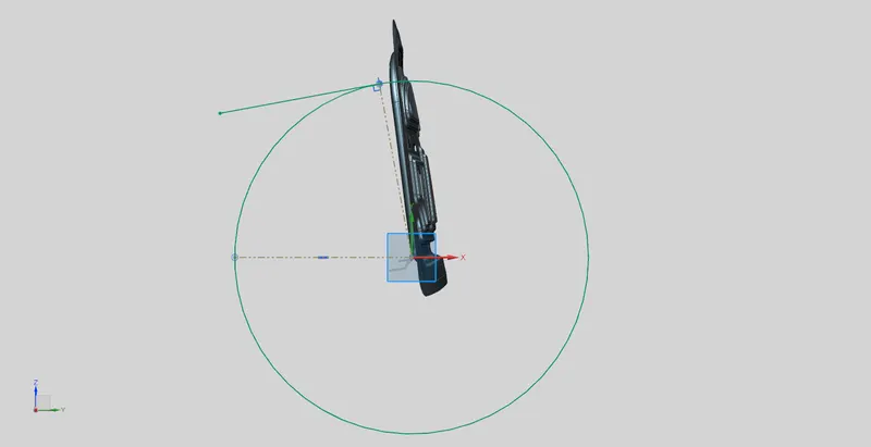
R= Centre of Striker to Hinge Axis axis point
- We can infer the circle to be the trajectory of Hood closing and opening.
| Move Component |
|
| Assembly Constraints |
Note: we have to Fix the Inner and Outer panel before working on them. |
| Datum Plane |
|
| Sketch |
|
| Emboss |
|
| Edge/Face Blend |
|
| Point |
|
| Curve |
|
STEP 5: STRIKER POSITION
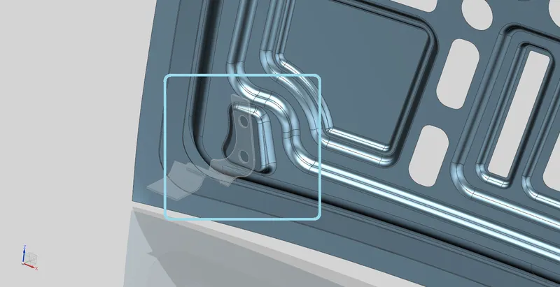
- In the Inner panel, draw a constrained Circle and a Tangential line.
- Constrain the line by introducing an angular relationship of about 80 degrees with a horizontal construction line.
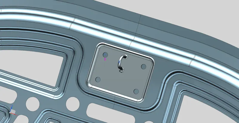
- In the Striker part, move the component as close to the local region and the tangential line of the circle.
- Create a Datum Csys (Coordinate system) at the top edge of the striker. Ensure that the X-Y-Z orientation is similar to the Assembly Datum Csys.
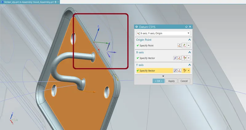
- Draw a perpendicular line from the centre of the latch point and ensure sketch constraints.
- Finally, Assembly constraint the Perpendicular line with the Tangential Line drawing in the Inner panel part.
- Change the Angle of the Tangential line to adjust the position of the Striker on the Inner panel.
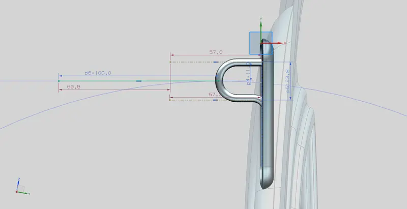
Note:
- This adjustable angle in the circle represents the trajectory of the Striker with respect to the Hinge axis point.
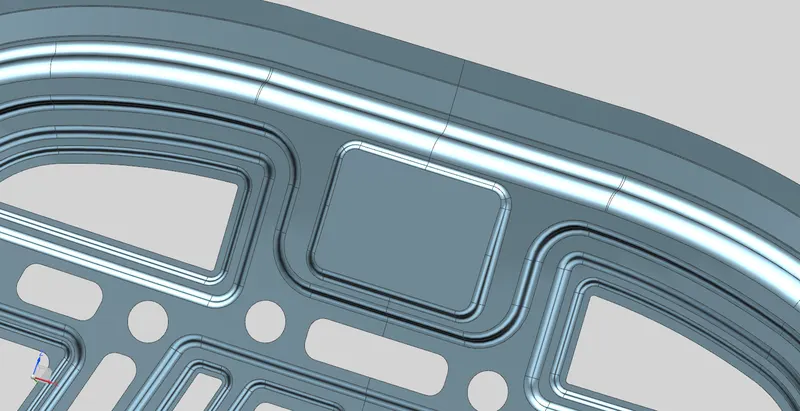
- As a result, we have determined the Opening and Closing trajectory of the Hood.
STEP 6: JOINING INNER AND OUTER PANEL
Both the panels are joined using the following design attributes:
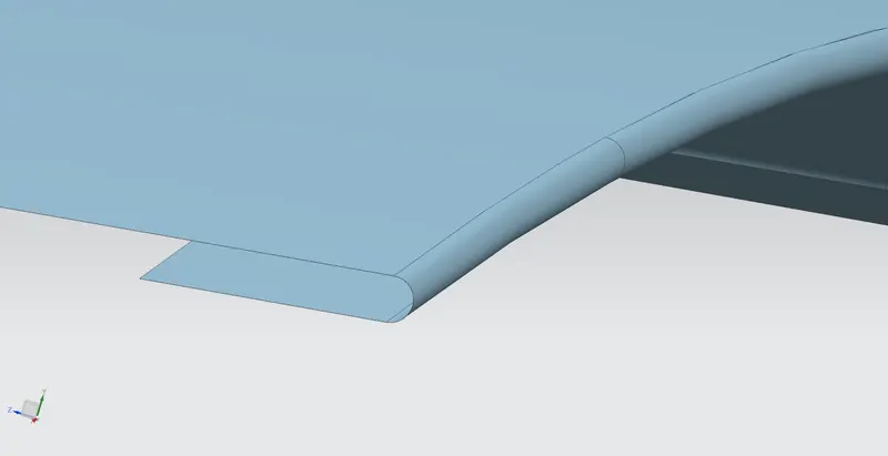
| Hemming |
Predefined Nomenclature
|
|
| Mastic Sealants |
Application
Predefined Nomenclature
|
Note: The Mastic sealants are just a visual representation to show the strengthening and joining capacity. |
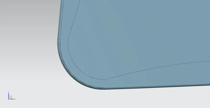
| Corner Relief |
|
 |
RESULT
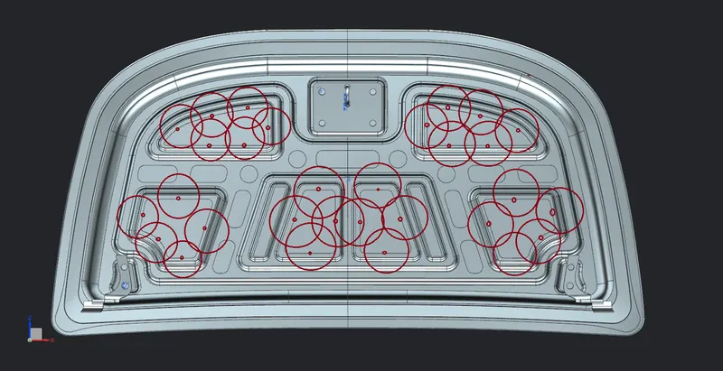
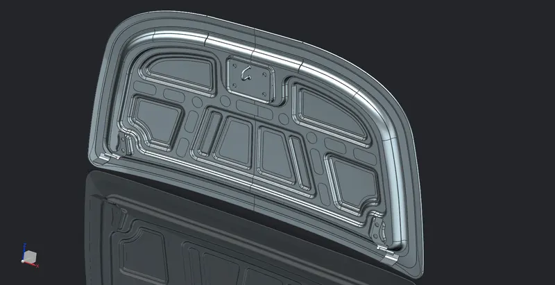
We have attained the Hood assembly that meets the respective design standards.
| NVH | Reduced NVH using Mastic sealants. |
| Latch and Striker point |
The Striker is exactly perpendicular to the trajectory at the local region. |
| Hinge Axis | Provided the Opening and Closing Trajectory for Hood, about the Hinge axis. |
| Pedestrian Rating |
Designed the Inner panel to reduce the rigidity and let forces get distributed sideways during a collision. |
| Euro N-CAP Regulations |
The Inner panel was designed taking the following into consideration:
|