Side Crash Test of Dodge Neon BIW Model using RADIOSS
Side Crash Test of Dodge Neon BIW Model using RADIOSS
Objective
To Perform a Side Crash Test and study the sectional forces, contact and intrusions to conclude the safety of the passenger.
Here is the Basic setup for Side Crash test:
i. Set the Unit system (Kg-KN-mm-ms).
ii. Balance the Mass and Centre of Gravity of the Car.
iii. Create a Rigid wall and Type 7 Interface without any penetration.
iv. Create Sections on the respective components.
v. Check Intrusions on the Dashwall.
vi. Study the Acceleration on the Rocker (B-Pillar base).
vii. Perform a Model checker to ensure error-free results.
Procedure
Step 1: Import
Import > Solver Deck > FIRST_RUN_0000.rad (select) > Import
- The starter file is in ASCII (American Standard Code for Information Interchange) format and contains model information such as:
- Nodes
- Load Conditions
- Velocity
- Boundary Conditions, etc.
[Note: The starter file should always end with 0000.rad. After changing the parameters (Eg. Velocity) and running the next simulation, the file becomes FIRST_NAME_0001.rad and so on.]
1.1 Delete existing Interfaces
We will be defining our own interfaces for the frontal crash test, so delete the existing interfaces.
Model > Groups > Delete
Step 2: Add Mass
Target weight: 700 Kg
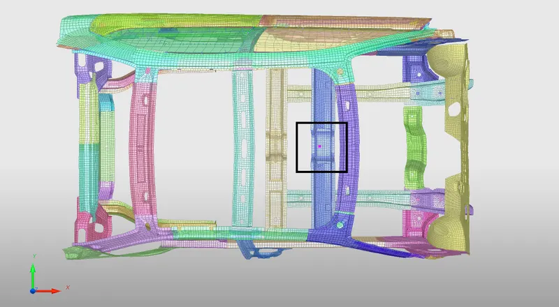
We have to add the mass in such a way that the Centre of gravity is exactly in the middle of the Cross Beam to simulate the real-time model.
We are only worried about the position of the COG (X and Y axis) and not the height (Z-axis).
We use Type 1 Mass, where mass is distributed on each node of the selected group.
Added Mass > Create New > Type =1 > Enter the Value (Eg. 100 Kg) > Select the group node by selecting in the graphics
Step 3: Create a Rigid wall
It is a Shell element with no thickness (gap) and infinite stiffness.
A search tolerance is given (optional) so that the nodes within the range will be taken as slaves.
We are going to create an Infinite Cylinder type Rigid wall.
[Note: To ensure that the Rigid wall is straight and not inclined, we have to create a temp node on the bumper and translate (Shift + F7) it along the global X-axis.]
Browser > Create > Rigidwall > Enter the coordinates of the Temp node [XM, YM, ZM] > Enter the Direction of the Normal [0, 0, -1] > Enter the Diameter of the Rigid wall (254 mm)
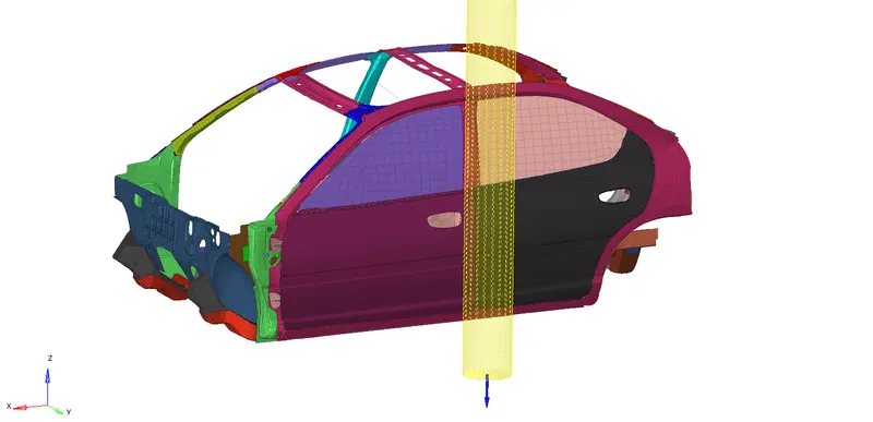
The rigid wall should be vertical with respect to the global coordinate system.
In this Interface, the Rigid wall is the Master, so we have to specify the Slave nodes by creating a set.
We have to provide frictional parameters for the rigid wall when the slave nodes come in contact:
| Friction type [Slide] | 2: Sliding with friction |
| Frictional Coefficient [FRIC] | 0.1 |
Step 4: Create Interface
The interface is the Interaction of Parts when they come in contact with each other. This leads to the Penetration of the Slave nodes into the Master Segment.
We are creating a type 7 Interface for:
Self [Master and Slave: Car Model]
The penetration caused by contact is governed by the Penalty Method. We will be giving Parameters in the Engine Card to make sure that the penetration doesn't happen.
| Control Card | Description |
| `I underset(stf` = 4 | Initial Contact stiffness |
| `Iunderset(gap`= 2 | Variable Gap + Scale Correction |
| `I underset (DEL` = 2 | The Failed Element gets deleted by removing the Master Segment in Contact and deleting the free Slave Nodes. |
| `St underset (min` = 1.0 | Minimum stiffness, to avoid Timestep error. |
| Fric = 0.2 | Columb friction, for modeling tangential forces between contact surfaces. |
| `Gap underset(min` = 0.5 | In case `Iunderset(gap` fails, `Gap underset(min` is used to avoid penetration. |
| Inacti = 6 | The Gap is reduced and removes Penetration error. Further Gap scaling is done to a factor of 0.8 |
| `I underset(FORM` = 2 | Friction formulation during contact (results in bigger timestep) |
Step 5: Plot Sections
i. We have to know how the forces are transmitted from the Bumper to the Dashboard and the rate of deformation. It is done in order to ensure the safety of the passenger.
ii. Certain components have to crash (deform) more than the other so that the forces are distributed correctly leaving very little force left to transmit inside the cabin.
iii. We are creating sections for the following parts:
| Part | Description |
| Front Cross Beam | Is in line with the front passenger seat |
| Middle Cross Beam | Acts as a support for the B pillar during Crash |
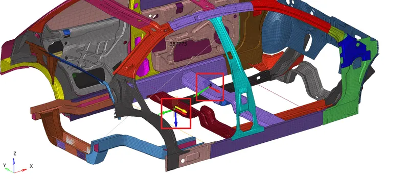
[Note: Make sure that the sections are placed along the same line on either side of the vehicle to study exactly what is happening on the sections of the left and right parts.]
iv. The Sectional forces should be transmitted in the following descending order:
Rail > Bumper Interface > Shotgun > A-Pillar
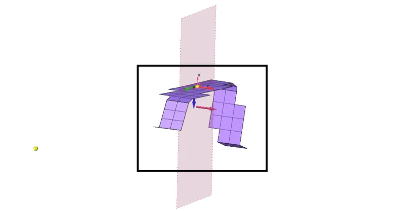
v. On each part, we introduce a Moving Frame that acts as a local coordinate system for the geometry. This will help us understand the Sectional forces passing through the Elements (around the cross-section of the geometry).
Create > Frame > Select the Nodes
| N1 | Origin |
| N2 | Axis (Z-axis) |
| N3 | YZ Plane |
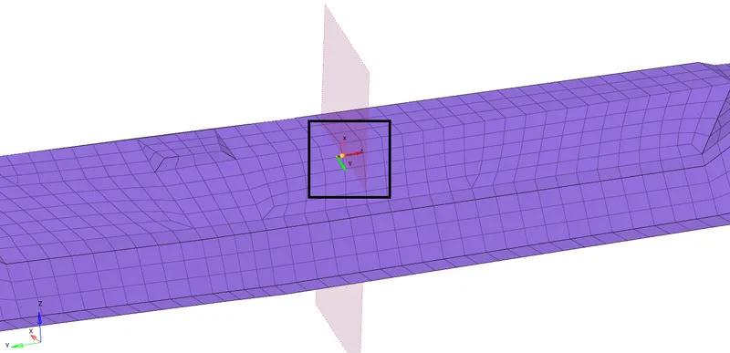
vi. Now we have to create a section with respect to the frame id. The section is created in order to select the elements around the cross-section.
Create > Section > Enter the Parameters
| Nodes | N1, N2, N3 |
| Frame id | Select the frame that we just created. |
| delta T | 0.1 |
| alpha (scale factor) | 0.67 |
| grshel_id | Select 2-4 rows of Shell elements about the frame, around the entire cross-section of the part |
Step 6: Initial Velocity
i. The Velocity is given in mph so we have to convert it into the required unit system, i.e. m/s.
| Velocity in mph | 35 |
| Velocity in m/s | 15.6464 |
ii. Initial velocity is a Boundary Condition defined to a group of nodes (car model).
iii. No function (curve) is required since it is instantaneous. Therefore, it reduces the computation time for the solver.
Parameters required:
| Velocity | 15.6464 [X], 0 [Y], 0 [Z] |
| Skew Id | Global System |
| grnd_Id | Select the nodes by creating a Set |
Step 7: Intrusions
i. To ensure the safety of the passenger, we need to know how the forces are transmitted inside the cabin from the impact on the outer door panel and B Pillar.
ii. So, we are planting Spring elements to study the intrusions (forces inside the cabin causing deformation/rupture).
iii. Create 3 parallel spring elements across the width of the car:
a. Hinge Pillar
b. B Pillar
c. Fuel Tank
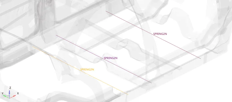
[Note: Make sure that the end of the springs is equally positioned on either side of the vehicle. They have to be along the direction of the normal forces due to impact.]
iv. Change the Spring properties in the card:
| Card Image | P4_Spring |
| Mass | 0.001 |
| Stiffness (K1) | 0.0001 |
[Note: The spring's properties shouldn't interfere with the computation so give Negligible Mass and Stiffness for the spring .]
Step 8: Peak Velocity
i. The impact of the rigid pole will cause the deformation to spread from the outer to the inner door panel.
ii. We have to check for the peak velocity of the inorder to understand the rate of deformation.
iii. This is done in order to ensure the safety of the passenger sitting beside the door during a side crash, if the peak velocity is too high then the model isn't safe.
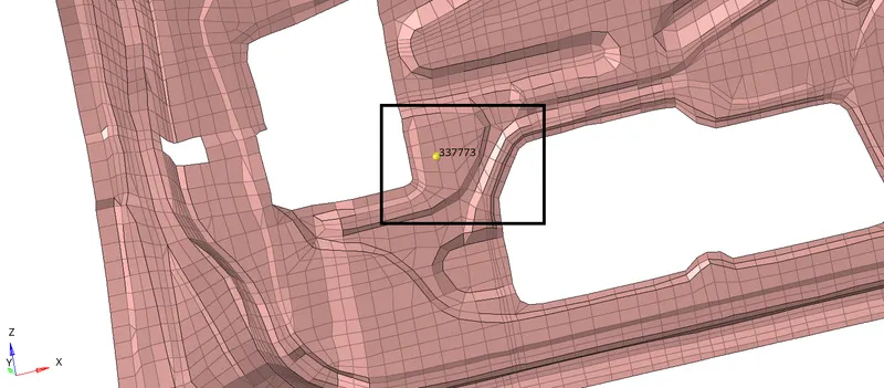
iv. We need to request for Time History of a node to get its peak velocity. While creating a TH card in the Solver browser, we select the respective node.
Solver Browser > Right Click > Create > TH > NODE
Step 9: Timestep Control
| Engine Card |
`T underset(SCALE` [Scale factor] |
CST [Constant time step method] |
`T underset(min` Critical Timestep |
Description |
| ENG_DT_NODA | 0.67 | Default | 0.0003 | Mass is added to the node when the computed timestep becomes smaller than the critical timestep. This card controls the Simulation. |
| ENG_DT_BRICK | 0.9 | Default | 0.005 | Controls the timestep by small strain formulation on the elements if they cause the timestep to drop. |
| ENG_DT_INTER | 0.9 | Default | 0.005 | Uses default constant timestep method. |
| ENG_DT | 0.9 | --- | 0.003 | We enter the Critical Time step here. |
Step 10: Call the Time History Files
i. They are Output files that are requested in the Starter File.
ii. All the Global variables (Internal energy, Kinetic energy, Contact Energy, Hourglass Energy, etc.) are already requested by default.
iii. We have to call for additional Time History files for the boundary conditions that we have created for the frontal crash model.
iv. We can create the Output requests from within the Solver Browser:
Solver Browser > Right Click > Create > TH > Select the Output Request
| Output Requests | Boundary Conditions |
| INTER |
i. Impact ii. Self |
| SPRING |
i. Hinge Pillar ii. B Pillar iii. Fuel Tank |
| RWALL | i. Cylindrical Rigid Wall |
| SECTION |
i. Front Cross Beam ii. Middle Cross Beam |
Step 11: Check for Penetrations
i. Although we have given all the Interface parameters (such as `I underset(gap`, `Gap underset(min`, Inacti, etc.) it is better to check for penetrations before simulation.
ii. Penetrations could be a result of not defining the interfaces properly, or incompatible kinematic conditions at contact, etc.
Tools > Penetration Check
| Groups |
Self |
| Minimum Penetration Depth | 0.5 mm (Same as `Gap underset(min`) |
Step 12: Model Checker
i. This is the last and final check for the model before giving it for simulation.
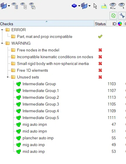
ii. The Model checker will give us any warnings and Errors regarding the model definition and, the boundary and Kinematic conditions, etc.
iii. For example:
a. Boundary Condition is not defined properly
b. Incompatible Kinematic Condition
c. The Part Property or material is not defined properly, etc.
iv. We can avoid the Warnings as the solver will take care of them.
v. But we must fix every Error in order to get a successful simulation free of problems.
Tools > Model checker > Radioss block > Check Runs
Step 13: Conduct the Analysis
Analysis > Radioss > Input File : (File Location) > Hit Radioss
i. The input file is the same Started file (contains model information) that we had just imported.
ii. The animation video along with the frames will be saved in the same folder where the starter file exists.
Step 14: Review the Simulation
We have to import the animation file in Hyperview first:
Hyperview > Load File > FIRST_RUN. h3d > Apply
i. The tools to review the simulation are available on Hyperview.
ii. Hyperview is a post-processing and visualization environment for FEA that gives the output of the analysis in a simulations format that is user friendly to understand.
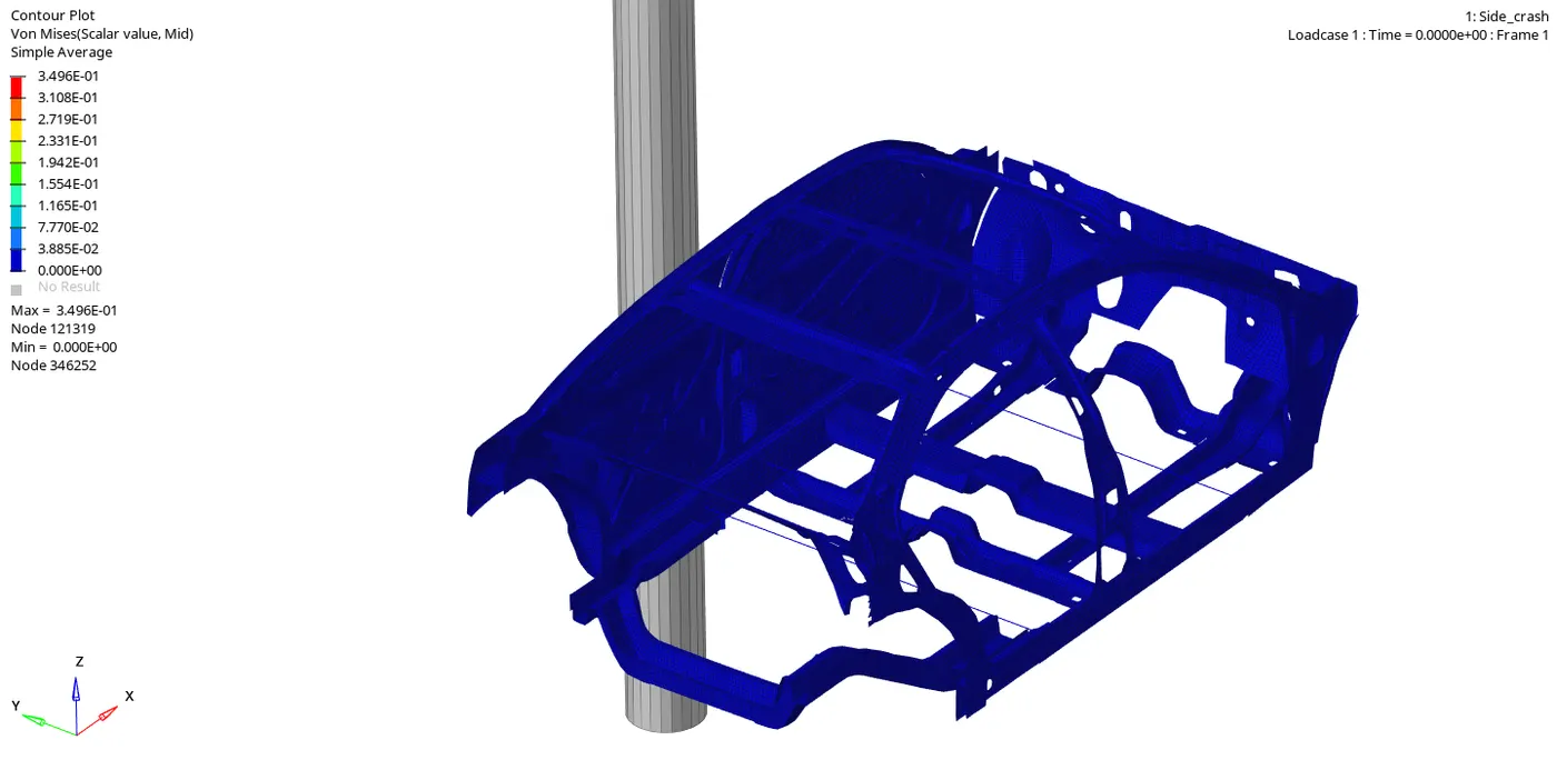
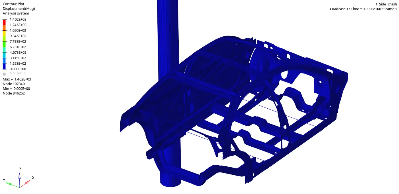
iii. From the simulation, we can review how the impact force acts and causes deformations and point of rupture on the model.
| Von Mises Stress (KN/mm2) | Displacement (mm) |
 |
 |
Step 15: Debugging errors
Check the Starter Output File for Errors:
i. A starter Output file of .out format is generated after analysis.
ii. The Output file contains the data during simulation, such as Cycle, Timestep, Energies, and Errors.
iii. We have to check for energy and Mass error.
iv. The Simulation tells only half the picture, we have to study the various energies acting on the system.
Note: There are some rules to be followed:
i. The error must be Negative and decreasing.
ii. It is normal if the error slightly increases and then increases.
iii. There is a problem if the error only increases, it will reach 99.9% showing computational failure.
iv. The Range for acceptable error is -15% to +5%.



Observation
i. The Energy Error is Negative and has been linearly increasing up to -1.7% only, which is acceptable.
ii. There has been an Initial Small strain Formulation on the Nodal Mass in order to control the Timestep and has lead to a very small Mass error in the first cycles itself.
iii. The addition of masses from then onwards has been very linear and gradual which is acceptable.
iv. We can conclude that there are no errors in the analysis.
Step 16: Plot the Graphs and compare the Results
The tools to plot the graph are available on Hypergraph.
Hypergrapgh 2D > Data File > FIRST_RUNT01 > Apply
Hypergraph is a data analysis and plotting tool that represents the FEA from the simulation in graphs with respect to the selected unit system.
|
Variables
|
Variable v/s Time | Description |
|
Global Variables [Kg*mm/ms2] |
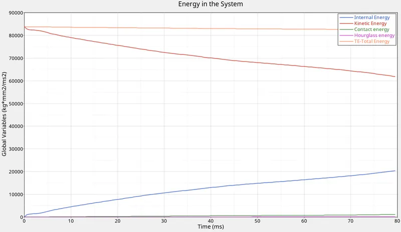 |
i. Ideally, the Total energy (TE) should remain constant, but there are bound to be losses during a contact. The negligible decrease is acceptable. ii. Internal energy, IE (Strain energy due to deformation) increases linearly as the contact increases. iii. The resistance of the Rigid wall causes the vehicle to a standstill. The Kinetic energy (KE) reduces gradually as it is being converted to Strain energy (Internal) and we can visually see that as Deformation in the model. iv. The Contact energy (CE) is very small, but increases very slightly over time as the deformation increases. v. Hourglass Energy (HE) is taken care of and doesn't affect the Timestep and Energy error. The Total Energy in the system remains constant will only -1.4% Energy error (due to small strain formulation). TTE = IE + KE +RKE + CE + HE |
|
Sectional forces at: i. Front Beam (Blue) ii. Middle Beam (Red) [KN/mm] |
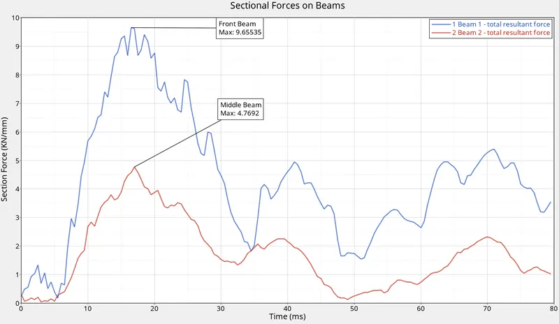 |
As the Impact is directly on the B pillar and it takes most of the force, the Middle Beam takes lesser sectional force as compared to the Front beam, due to the support of the B Pullar. The sectional Force on Front Beam is twice as much as the Middle beam. But the simulation gives a different picture. The deformation is more on the Middle Beam. This is because the structural support member under the Front beam prevents it from deforming a lot. The front passenger sits right above the front beam and lesser deformations on it confirm the safety of the front passenger. The sectional forces are peaking at different periods (40ms and 70ms) and we can see further bending at that instant. This is due to the opposing forces: i. Resistance of the Rigid wall ii. Moment of Inertia due to Initial Velocity |
|
Resultant Forces in Self Contact [KN/mm] |
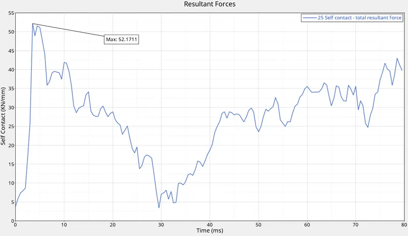 |
Maximum Force is established at the Initial Impact with the Rigid wall (3.5 ms). The Stiffness of the components allowed them to resist the Impact and therefore we see a gradual decline in the Resultant Force. But after 30ms, the deformation begins to increase. The Stiffness of the Beams is gradually decreasing and their resistance to Bending also decreases. The free ends of the beams are still continuing their state of motion due to the Initial Velocity (Law of Moment of Inertia). This causes an increase in Forces on the member, along with the Resistance force by the rigid wall. The Kinetic Energy of the Moving Sidecar is being converted to Internal Energy (adding to the Resultant forces) and trying to resist the bending. |
|
Intrusions on: i. Hinge Pillar (Blue) ii. B Pillar (Red) iii. Fuel Tank (Green) [mm] |
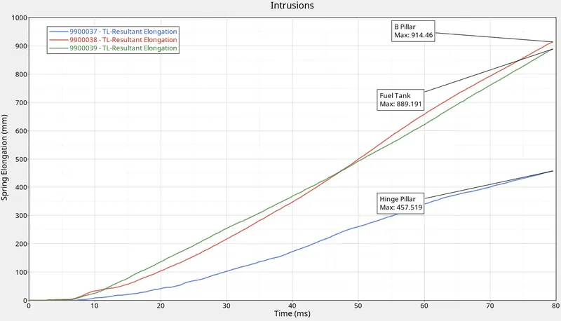 |
Since the Rigidwall is directly in contact with the B Pillar during Impact, the Intrusions on the B Pillar are maximum (914.46 mm) as expected. The second most intrusion occurs on the Fuel tank (889.191 mm), we can see that is almost close to the b Pillar intrusion. That is because it is connected along with the base of the B pillar (Rocker). In the Initial Simulation, we could see the part flying away, we had to give extra connections to keep it intact for the final simulation run. The least intrusion occurs on the Hinge Pillar (457.519 mm), which is half of the intrusions on the B Pillar. This ensures the safety of the front passenger as the front seat is just beside the hinge pillar. |
|
Peak Velocity of Inner Door Panel [mm/ms] |
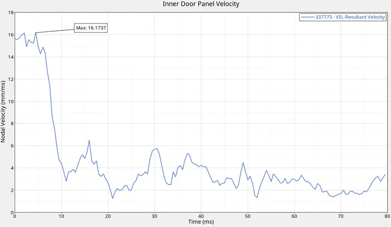 |
Due to the sudden impact, the rate of deformation is so high and it passes through the Outer Door panel, then Middle Panel, and finally the Inner Panel within 4.5 ms. After that, the velocity drops indicating that the rate of deformation on the inner door panel is reduced and reaches almost constant as the Forces are getting distributed to other connected components. But the Velocity is not entirely constant, as there is a frequency caused by the shockwave from the impact. |
Conclusion
From the Simulation Animation and the Plots, we can conclude that:
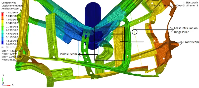
i. The Forces on the Front beam is high, but it offers more resistance due to the structural support member underneath it. This means that the Front beam prevents further intrusions inside the cabin and ensures the safety of the front passenger who is sitting right above the front beam.
ii. The B pillar acts as a perfectly structural member and taking most of the intrusions thereby allowing lesser intrusion on the Hinge pillar which is beside the front passenger seat.
Learning Outcome
i. The minimum conditions required to set up a side crash test.
ii. How the Cylindrical Rigid wall interface works and it can lead to incompatible Kinematic conditions.
iii. How Sectional forces are generated during a Side crash.
iv. How some components are designed to deform in such a way to ensure the safety of the passengers inside the cabin. Such as the Middle Beam undergoes more deformation than the Front beam inorder to keep the passenger safe as the front seat is right above the front beam.
v. Understanding the rate of deformation during Side-impact, from the Peak velocity curve and able to predict the safety of the Passenger.
vi. Check for Energy, mass, and momentum balance
vii. Debugging errors in order to get the right results.