Front Fender Design with Mounting Points
BIW FENDER DESIGN FOR MOUNTING
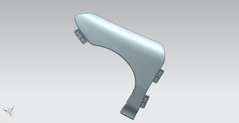
To create a Front Fender, a styling component that covers the Engine compartment from the side.
- Incorporate the right Mounting points.
- Meet the Gap and Flushness requirements.
- Follows Offset Frontal Crash regulations
DESIGN PRINCIPLES
- The Fender is a styling component that acts as a frame for the wheel arch.
- The primary purpose is to prevent sand, mud, rocks, and liquid that gets sprayed from the rotating tyre, into the engine compartment, car body pedestrian.
1. Type of Bumper
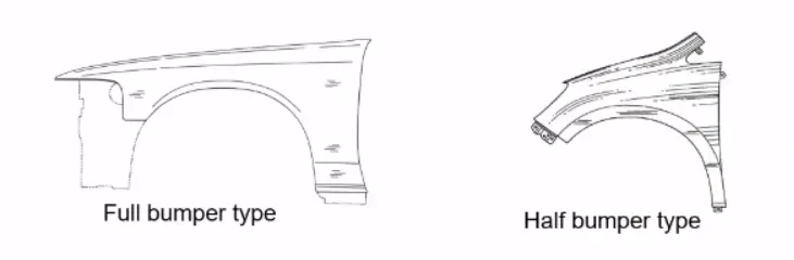
- Full Bumper (Less preferred)
- The Fender extends beyond the Headlight mounting to the Bumper interface.
- The Blank for the Fender is bigger and material is wasted, thereby increasing the cost.
- Half Bumper (Most preferred)
- The Fender is trimmed right before the Headlight mounting.
- It allows the Bumper to extend beyond and thereby increasing Pedestrian Safety.
- 2 Fenders can be produced from a single blank thereby saving material, cost, and production time.
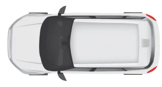
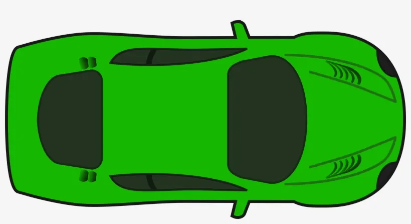
2. Wheel Well
| Narrow Car Body | Wide Car Body |
|
The fender is an exposed curve over the top of the tire
|
The wheel well surrounds the tire and is not visible from the top view.
|
3. Wheel Arch Area
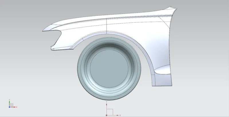
- A semicircular arch that provides clearance for the tire to facilitate:
- Steering of the wheel (sideways)
- Suspension of the wheel (up/down)
- Different regions (US, Europe, Japan, etc.) have different regulations to meet their road requirements.
4. Mounting Points
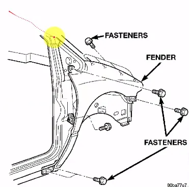
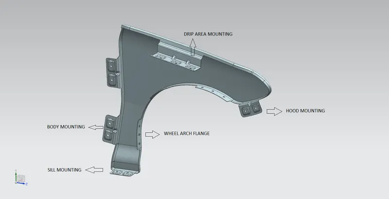
- The Fender is mounted at 5 points:
- Body
- A-Pillar
- Sill
- Cowl
- Drip
PROCEDURE
STEP 1: INPUT
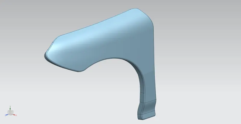
- We get the Class A surface with predefined edges from the Styling Team.
- We get a Master Section as well, which is a predefined sketch that is adaptable to different situations.
- As Design Engineer, we check for the initial feasibility and whether the part has to be raised/lowered.
Note: We don't have reference data like the engine compartment, we can go ahead with designing the engineering features.
STEP 2: DRIP AREA REQUIREMENTS
1. Drip Area Clearance
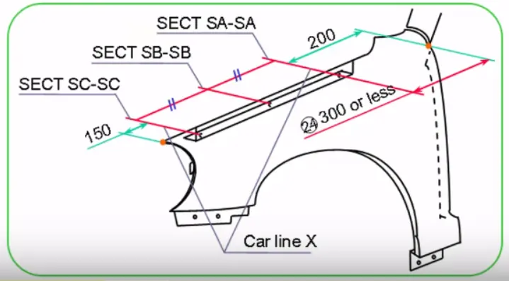
| Wiper Motor Clearance |
200-300 mm clearance should be provided to accommodate the wiper motor which is placed in the Engine compartment. |
| Headlamp Housing Clearance | Exactly 150 mm clearance should be provided for Housing the Headlamp and its electronic accessories. |
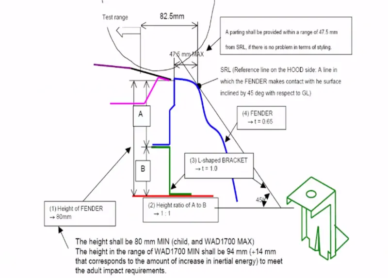
2. Pedestrian Safety
|
47.5 mm parting from the Side reference Line, which makes contact with the surface inclined by 45 degrees with respect to the Ground level. Height of the Fender to meet theHead Impact zone:
|
3. Gap and Flushness
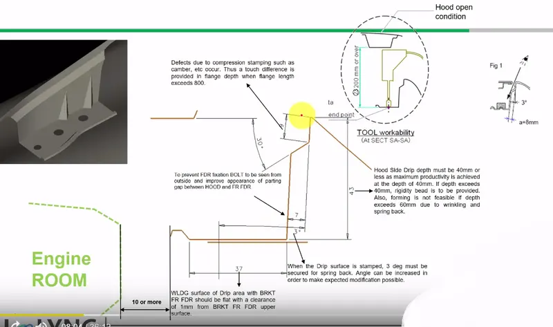
| Drip Depth |
|
| Touch Difference |
|
| Draft |
|
| Parting Gap |
|
| Welding surface |
|
| Engine Room |
|
4. L Shaped Bracket
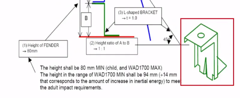
- The Bracket is used to fix the Drip area of the Fender onto the Engine Compartment.
- The Ratio between The Drip Height and the Bracket Height is 1:1.
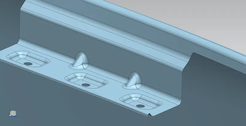
STEP 3: Emboss design for Bolts
The Bolted regions are prone to stress concentration. Therefore, we add reinforcement members like Emboss to add local strength to the mounting region.
The Emboss is provided on the following mounting regions:
- Drip Area
- Body
- A-Pillar
- Sill
- Cowl
Design Rules to be followed to meet Manufacturing standards:
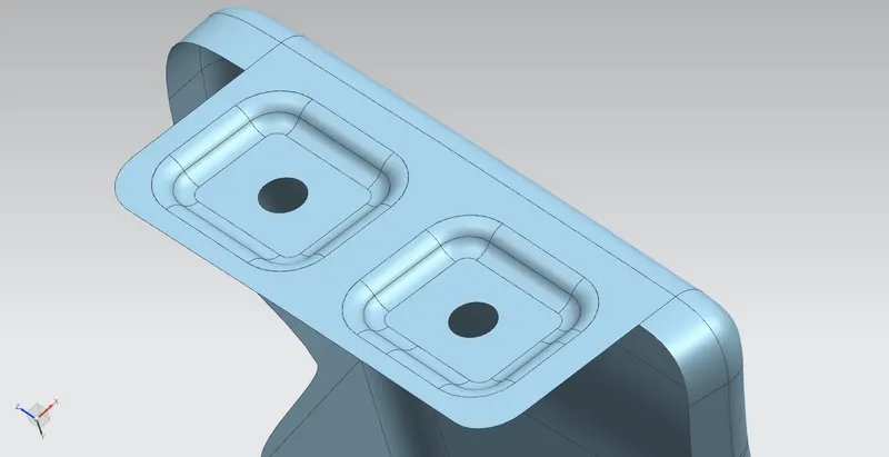
| Draft Angle |
|
| Emboss spacing/clearance |
|
| Clearance for Material removal |
|
| Dart |
|
Functions performed for creating the Emboss:
| Offset surface |
Note: The Offset dimension is limited up to the Radius of the surface (if curved). But if the surface is complex then it gets distorted from a far distance, well within the limit. |
| Offset curve on surface |
Note: Ensure the curve gets,
|
| Trim sheet |
|
| Through curves |
|
| Law extension |
|
| Emboss |
|
| Face blend |
|
| Edge blend |
|
| Sketch Tools |
|
| Project Curve |
Note: We cannot sketch on a curved surface. Therefore, we sketch on a datum plane and project it onto the respective surface to get an accurate section of the sketch. |
Step 4: Wheel Arch Flanges
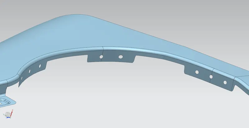
- The Wheel arch acts as a frame for the Baffle plate which is a plastic sheet that prevents the spreading of mud, sand, etc.
- It is fixed using plastic fixtures and locators therefore, it doesn't require any emboss reinforcements.
- The Flanges are provided with well-spaced 5mm holes.
Step 5: Corner Reliefs
- To avoid stress concentration at sharp edges and corners, we provide relief.
- The CAE team studies the stress concentrated region, which is indicated as Red/Dark zone
Step 6: Thicken
- Once we have generated the required geometric features with blends and sews generating a single surface sheet, we give a uniform thickness of 0.65 mm.
RESULT
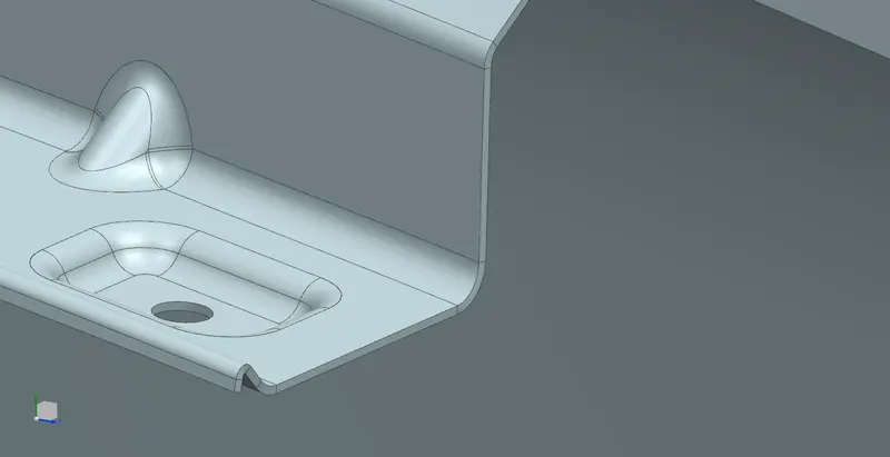
We have attained the Front Fender part with the respective design standards.
| Drip Area Requirements |
Wiper Motor Clearance Headlamp Housing Clearance Pedestrian Safety Gap and Flushness |
| Emboss design for Bolts |
The Emboss is provided on the following mounting regions:
|
| Wheel Arch Holes | Baffle plate mounting holes |