Preprocessing of Hood Model using Hypermesh
Preprocessing of Hood Model using Hypermesh
Objective
- Generate a good Mid surface.
- Manual clean up on the surface and mesh.
- Learning how to mesh on the Hood model by using clean up tools.
- Making sure the quality criteria is maintained and free of errors.
- Maintaining Tria percentage.
Procedure
Step 1 : Importing
Since we are importing a CAD geometry, the format will be either of the 2:
- STEP (STandard for the Exchange of Product data).
- IGES (Initial Graphics exchange specification).
These 2 are Industrial accepted standards.
When selecting the file for import, be sure to check if it is .stp or .IGES.
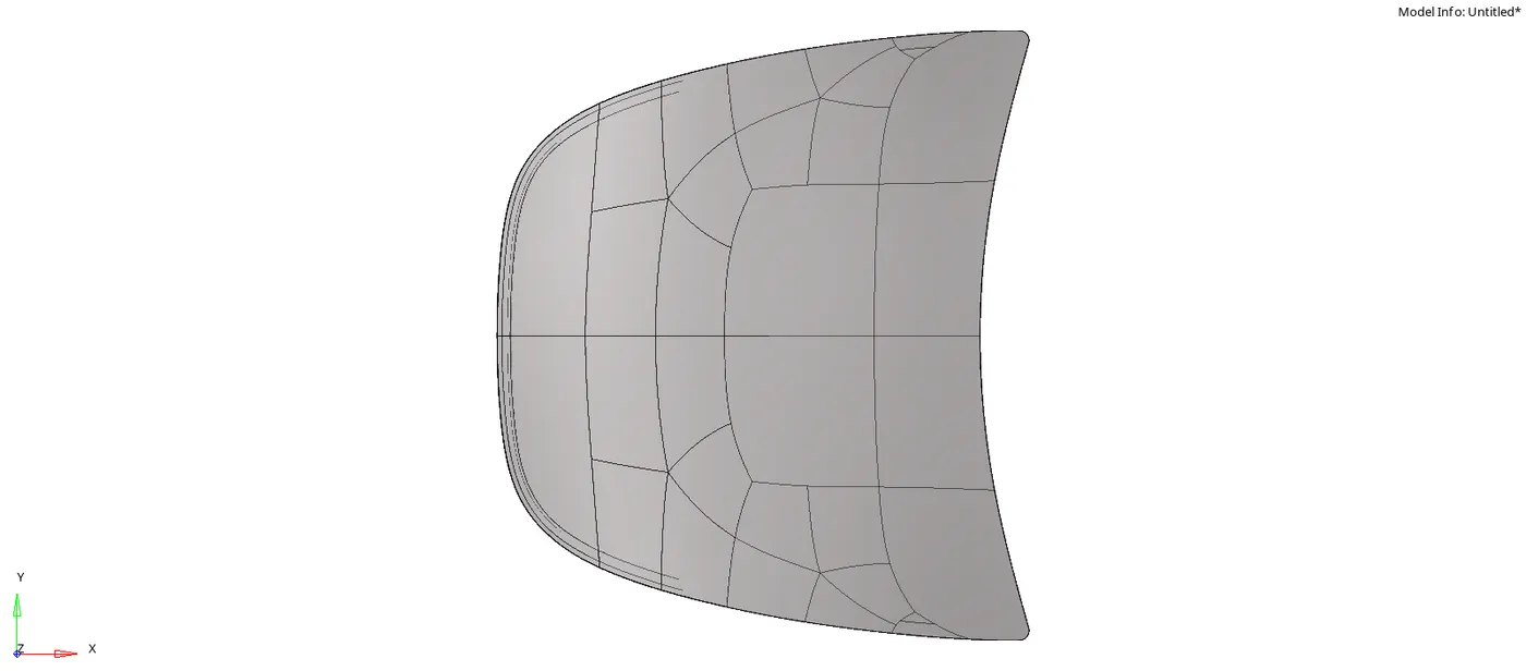
Step 2 : Inspection
- Due to the complexity of the design, some features might not be captured well.
- It is the duty of the CAE engineer to fix these errors by Manual cleanup and generate a clean geometry free of errors, so that good meshing can be performed.
- Before working on the model, we have to first check for the type of errors that we have to fix, such as :
- Surface deformations
- Free edges
- Unnecessary Connections (Extra points and lines)
- Connectivity error
- Upon inspection, we can see that there are 5 Components :
- Latch
- Left Hinge
- Right Hinge
- Inner Panel
- Outer Panel
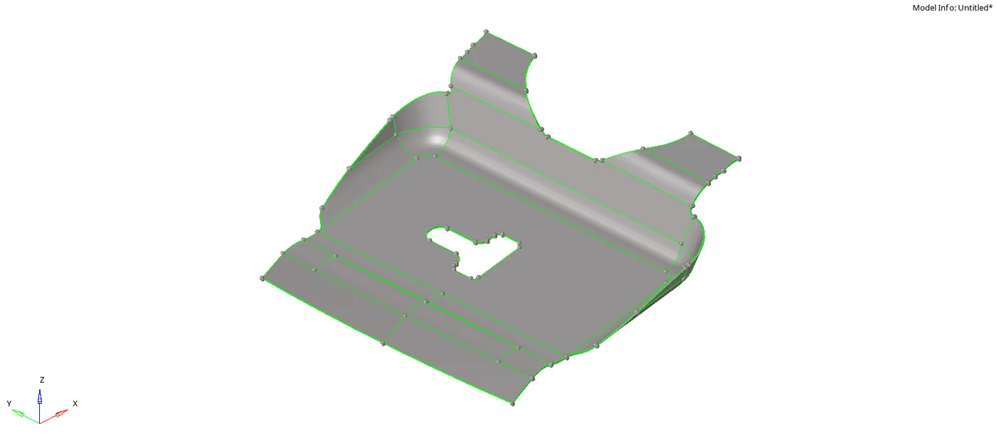
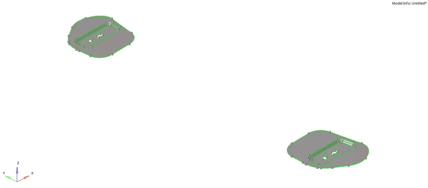
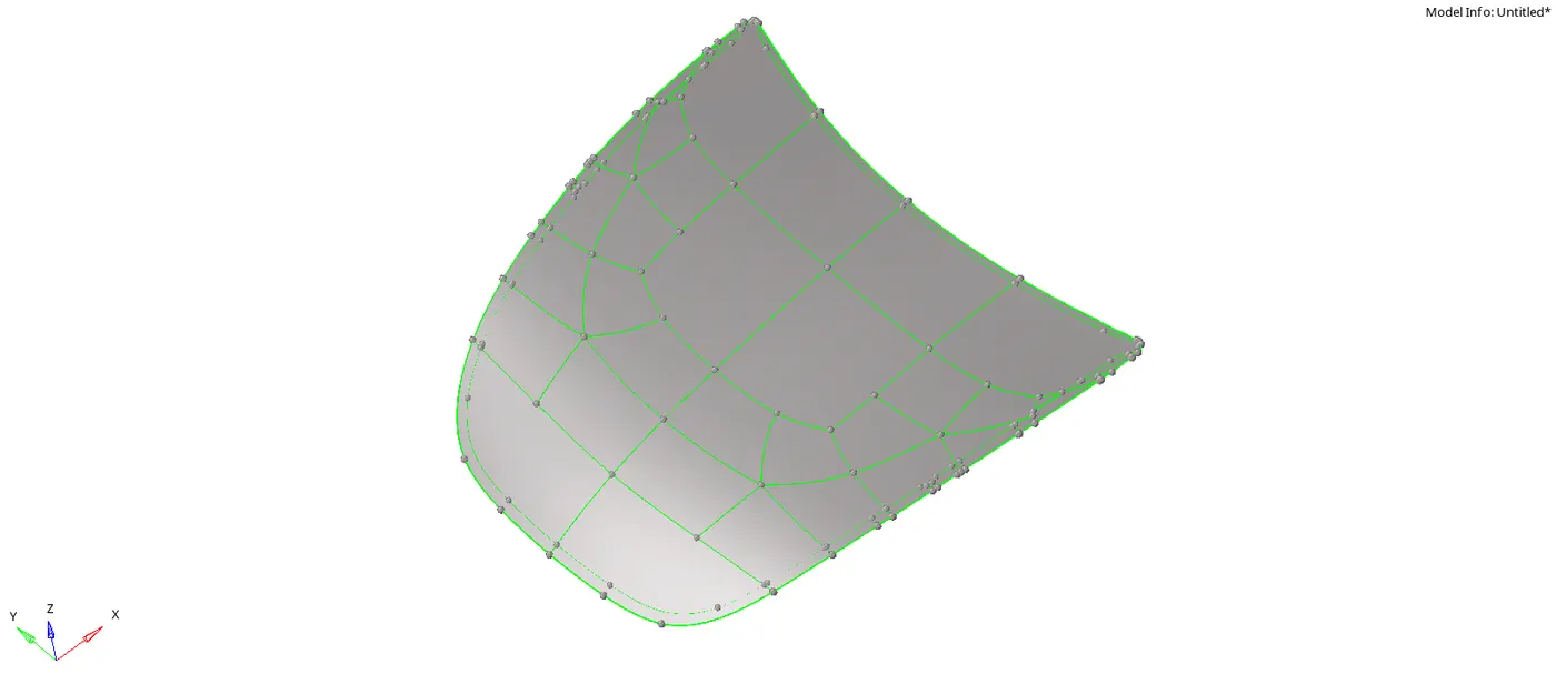
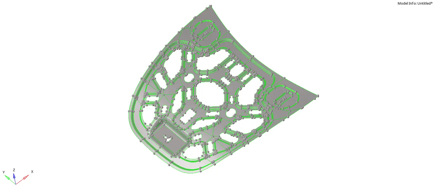
- It becomes easier to check for dimensions when we enable Display Fixed points.
- Upon checking for dimensions, we can see that the thickness is less than 6mm. Therefore, it is considered as a Sheet metal.
Step 3 : Extract the Mid surface
- Use Skin Offset as it allows the user to capture most of the featurings on the mid surface.
- Upon creating Mid surface, it is saved automatically as a new PSHELL component.
- Rename the component.
3.1. Assign Component
- Create a New Component before extracting the mid for the next component.
- If we skip this step, then the new component will be saved to the previous one. An empty component will be created.
- Assign the Mid surface created, to the new component.
- Change the New Component as Current Component.
- Now, transfer the Mid to the Current Component (Eg. Hinge).
- Tools > Organize > Current Component > Move
3.2. Assign property and Material
3.3. Check for Symmetry
- From inspection, we observe that:
- There are 2 symmetric parts:
- Inner Extract
- Outer Extract
- There are 2 identical parts, but reflected about an axis
- Left Hinge
- Right Hinge
- There are 2 symmetric parts:
- For the Inner and Outer extract, we can delete one half of the surface along the symmetric axis (X Axis in this case).
- Delete > Surfs > Select > Delete Entity
- For the Hinges, we can just work on any one and reflect the mesh and surfaces later.
[Note : This is a very crucial step as it saves half the time and effort.]
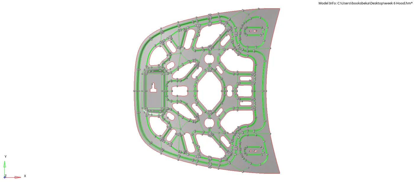
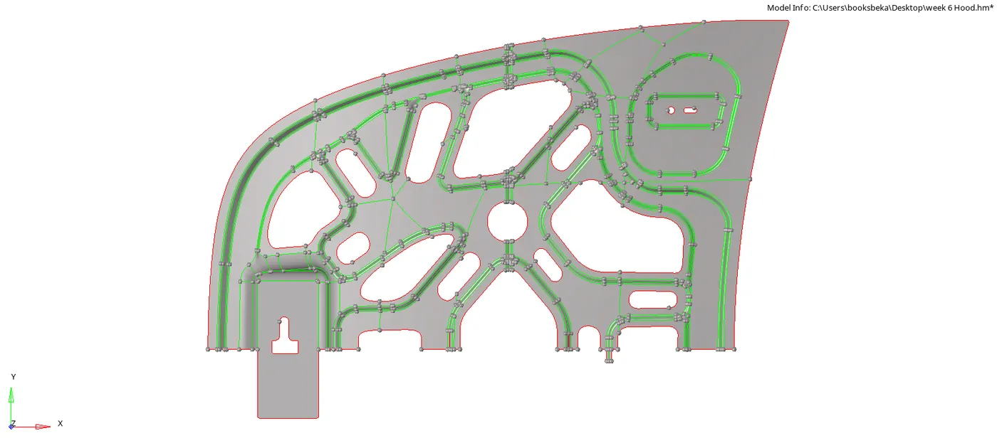
Step 4 : Manual Clean Up
- Manual Clean up is done for the following reasons:
- Generate a good mesh flow.
- Making sure it doesn't fail for Minimum length.
- Surface deformations.0
- Connectivity errors.
- Making sure the features are captured properly.
4.1. Perform Defeaturing if needed
- In some surfaces, the feature might be curved (inwards) and will affect the mesh flow.
- Defeaturing changes the inward curve to a corner , making it easy to mesh on the particular surface.
- If the feature is not so important (Eg. Key Slot), then we can go ahead and defeature it.
- Geom > Defeature > Edge Fillets > Select surfs > Find Fillets > Remove
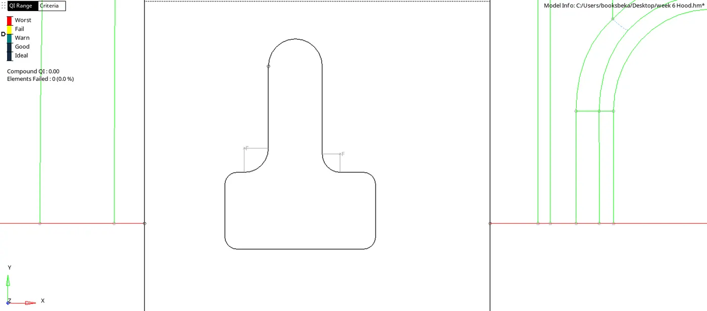
4.2. Fix for Minimum Lenth and Toggle Extra lines
- we have to make sure that the length of any line or distance between any points is above the Minimum length (2mm).
- The fastest option for this fix is the toggle edge which is a tool under quick Edit [F11]
- quick Edit > Toggle Edge > Left click to Toggle
- There will be extra lines on the flat surfaces, we can toggle them by using the same option.
- Incase, we need to untoggle a line back:
- Quick Edit > Toggle edge > Right click to Untoggle
- Even Replace points works for correcting minimum length error, but it takes extra few seconds to select the Replace point and Retained point.
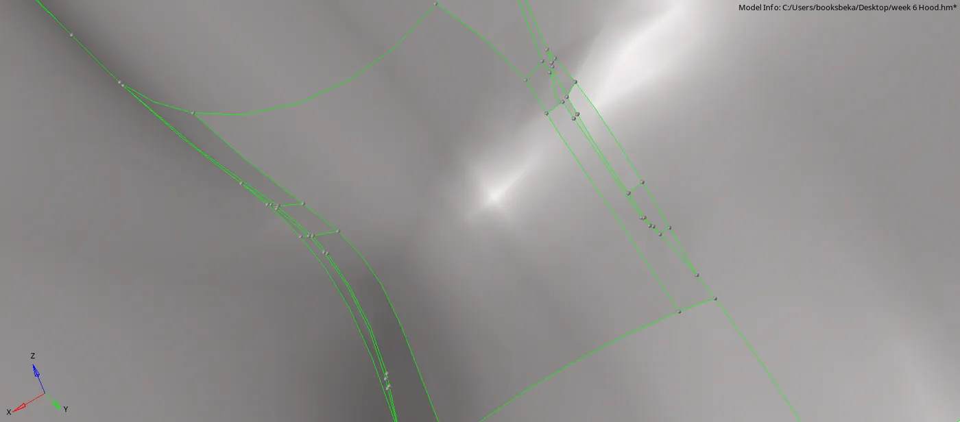
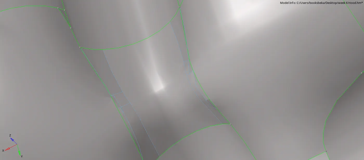
4.3. Fix Deformed surfaces
- Deformed surfaces occur due to the following reasons :
- Overlapping surfaces
- Connectivity issues
- The error can be best rectified using the combination options :
- Release point & Toggle edge
- Add/Remove point & Replace point
- Release point
- This allows the user to release the point causing a complex connectivity
- Once the point is released the green lines turn to red, which means the lines pertaining to that point are disconnected from the geometry.
- Geom > Quick Edit > Release points > Select the points to be released.
- Toggle option
- Toggle Edge > Right Click on the line
- Upon releasing the points, we can rectify the lines.
- If we want to Toggle a particular line :
- If we want to untoggle a line :
- Toggle Edge > Left click on the line
- It is better to not rely on deleting a surface and creating a new one as it is a complex part, the features might not get captured properly.
4.4. Split the mid into parts
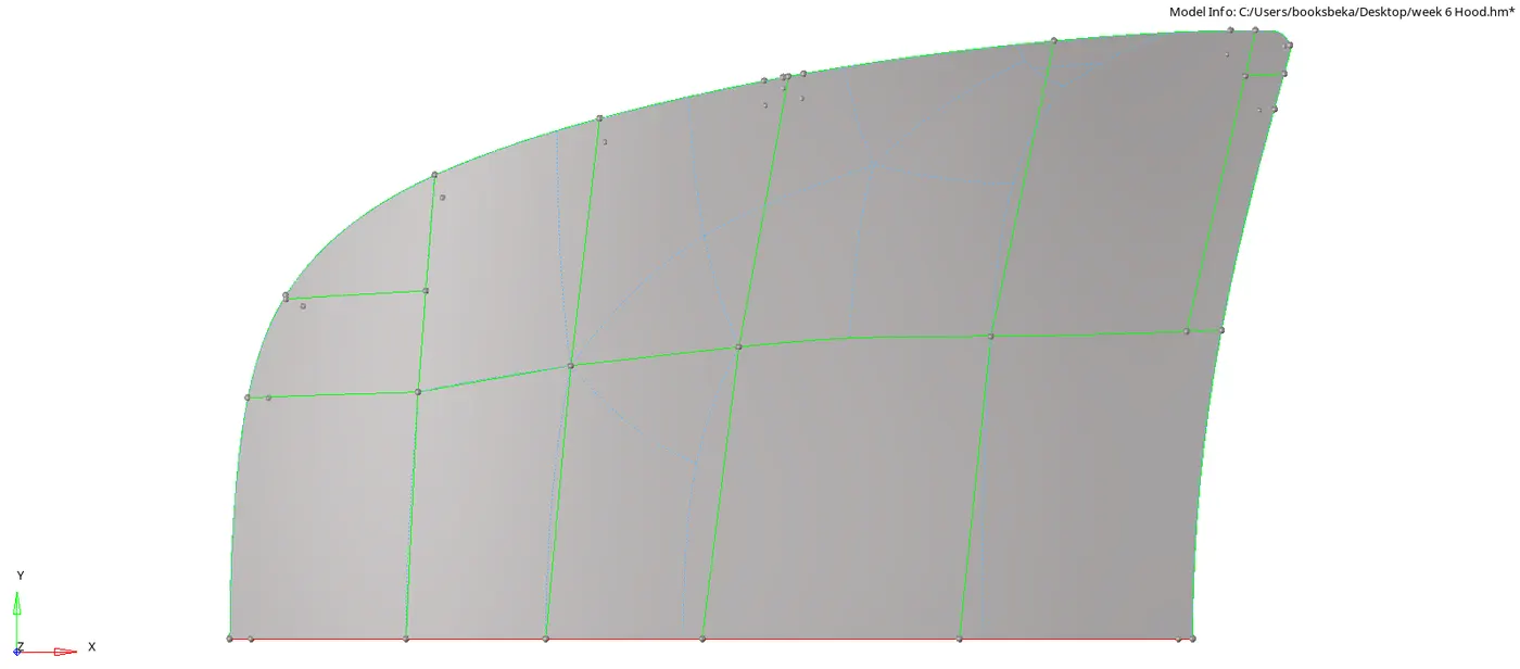
- If we directly give automesh on the entire part, we have to spend more time on fixing the quality errors afterwards.
- Therefore, split the respective surfaces in an apprpriate manner that would give us a good mesh flow.
- For Splitting a surface with Quick edit tools [F11] :
- Split surf-node (By selecting nodes)
- Allows us to cut on any complex feature without causing any surface deformation.
- Only limitation is that, nodes should be present. If there aren't any thn we have to add one.
- In some cases, we can make a cut without the help of nodes but the line may not be perfect.
- Quick Edit > Split surf-line > Select 1st Node > Select 2nd Node
- Split surf-line (By selecting Lines)
- This option allows us to cut perpendicular lines.
- It is limited to only staright surfaces.
- If we use this for fillets or curved features, it will create a staright line between the selected point and line and leads to surface deformation.
- Quick Edit > Split surf-line > Select Node > Select Line
- Split surf-node (By selecting nodes)
- Another option for making big splits/cuts on large flat surfaces:
- Trim with lines
- This option allows us to cut any flat surface across any cross section quickly.
- Geom > Surface Edit > Trim with Lines > With Cut Lines > Select surface > Drag a Cut Line > Middle Click
- We can use With Offset Line and create an offset line too. This option is available in the same command window under Trim with Lines.
- To know the magnitude of the offset, press F4 to check for distance.
- Trim with lines
Note : Try completing this operation throughout the entire part so that we can completely focus on only Meshing afterwards.
If we make a mistake during meshing and wish to make changes to the surface geometry, follow the steps below :
- Go to Call Options Panel [O] and set to Keep Mesh so that the mesh doesn't change.
- Call options Panel (Press O) > Mesh > Keep Mesh
- Once, we are done with making changes on the geometry we can change it back to Advanced Mesh and work on Meshing.
- Call options Panel (Press O) > Mesh > Advanced Mesh

Step 5 : Perform Meshing
5.1 Enter the Quality Criteria
- Tool Bar > Preferences > Criteria file settings > Check for the criterias > Enter Value > Apply > OK
Before Meshing, we have to first input the quality criteria:
| Sl. No. | Quality Criteria | Value | |
| 1. | Aspect Ratio | Ratio of Max. Length by Min. Length | 5 |
| 2. | Skewness | Deviation from the ideal shape | 45 |
| 3. | Warping | Angle between the 2 planes of the same element(Quad) | 15 |
| 4. | Taper | Convergence of a Quad element | 0.5 |
| 5. | Min. Length | Shortest length of any given element | 2mm |
| 6. | Max. Length | Longest length of any given element | 8mm |
| 7. | Min angle Quad | Minimum angle in any given Quad element | 45 |
| 8. | Max angle Quad | Maximum angle in any given Quad element | 135 |
| 9. | Min angle Tria | Minimum angle in any given Tria element | 20 |
| 10. | Max angle Tria | Maximum angle in any given Tria element | 120 |
| 11. | Tria % | Percentage of Tria on any meshed surface | 10 |
5.2. Rules to be followed while meshing
Before begining to Mesh, there are some certain rules to be followed regarding Tria Management, in order to generate a good mesh flow:
- No Opposite Trias
- No Trias on edges (Especially Free Edges)
- No Trias on Corners
- Avoid Trias on Fillets
- Avoid Rotating Quads
[Note : Trias are mush stiffer elements than Quads and therefore, if they are in the regions as mentioned above, the part is most likely to fail in those regions. Therefore, it is best to perform meshing by keeping those rules in mind.]
While Meshing we have to select the right type of Mesh to get a good mesh flow :
- Quads : For Rectangular/Square surfaces
- Mixed : For Irregular surfaces
[Note : Begin meshing from the regions of : Least Free Edges (or) More Features.]
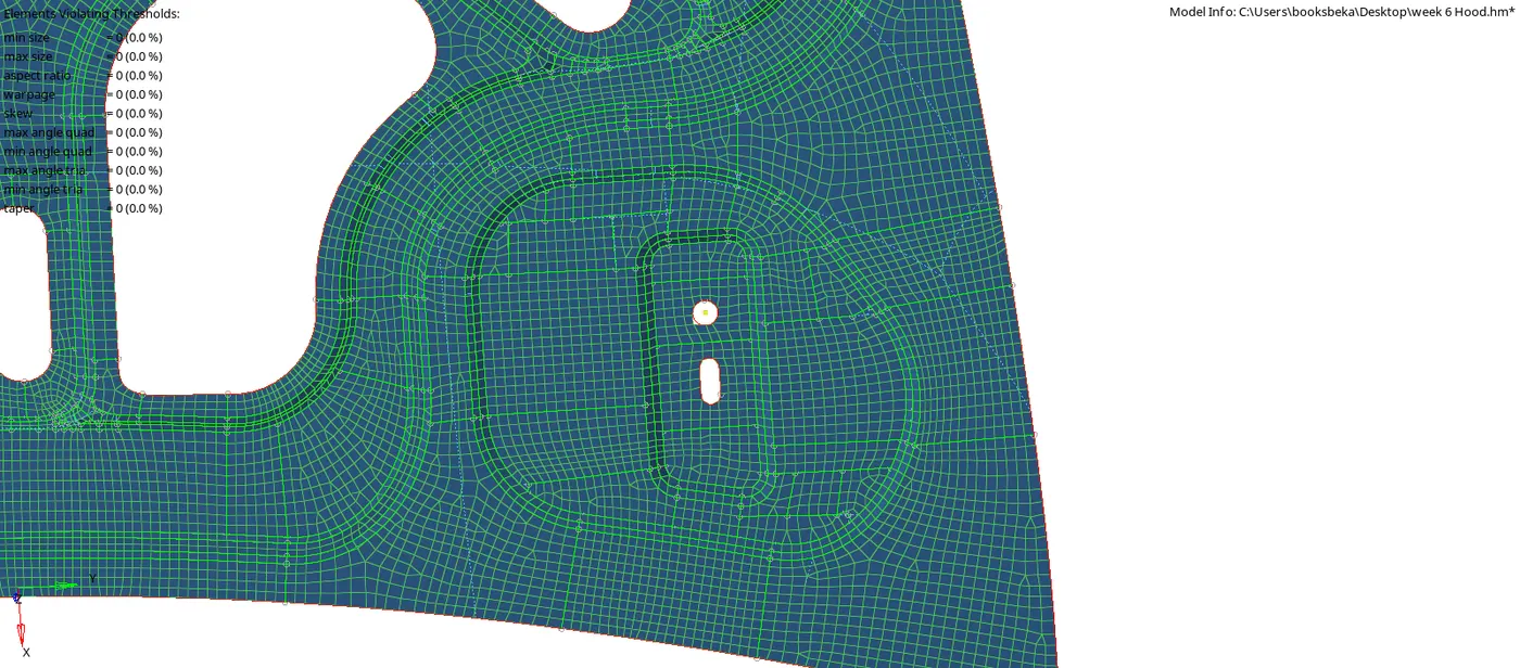
Start meshing from the following regions:
- Least Free edges
- Ideally from the centre (depends on the part) and working our way towards the edges.
- Reason : It becomes easier to clean up and requires less fixing/changes.
- Mesh density plays a big role in starting with meshing.
- If we start from the edges and work our way towards the centre, we might face erros as we might've been wrong in selecting the appropriate mesh density.
- More Features
- Since it takes more effort to get a good feature capturing, it is advisable to start from there.
- Reason :Less time consuming and less prone to errors.
- It is easier to clean up on flat surfaces. Therefore, if we start from there and get the Mesh density wrong we have to start all over.
5.3. Begin Meshing [F12]
- Select the appropriate mesh based on the shape of the surface.
- 2D > Auto Mesh > Surfs > Element size > Mesh Type > Mesh
- Once we give for mesh, we can edit the mesh density by changing the number of nodes.
- After trial and error, select the best combination of density by following the Tria Management rules.

5.4. Give for Remesh [F12]
- If required, give for remesh by selecting the surfaces.
- 2D > Auto Mesh > Elems > Mesh Type > Mesh
- If we wish to remesh the entire surface:
- Elems (Right Click) > By Geoms
- If we wish to only remesh a certain region of the surface :
- Box select [Shift + Drag].
- To get better results, box selecting a square/rectangle or even till the edges if you can.

Reasons for following this step :
- Almost half the clean up gets done by selecting the appropriate elements.
- Saves half the time and effort spent on Clean Up (Quality Index).
- Generates a much better mesh flow with most of the qualirt criterias.
5.5. Using Clean Up tools [Q]
- 2D > Quality Index > Clean Up Tools
This option allows us to make any changes to the elements on the mesh. the tools are listed below:
| Sl. No. | Tool | Function | Advantages | Limitations |
| 1. | Smooth | Clears the quality directly by just box selecting the elements | Instantly clear for quality criteria. | Overdoing affects feature capturing |
| 2. | Drag Tria Element | Drag any tria across the mesh flow | Easily Join 2 opposite Tria elements | |
| 3. | Swap Edge | Swag edge from one element to the next | Individually fixing elements | |
| 4. | Split Quad Element | Splits a quad into 2 Trias | ||
| 5. | Combine Tria Elements | Combines 2 Tria elements into 1 Quad | Reduce Tria percentage | |
| 6. | Element Optimize | Smooths the quality by just clicking on the element | Clear for quality | Affects feature capturing |
| 7. | Place Node | Allows the user to manually change the position of a single node | Manually work on the individual element and fix for the quality | Accuracy |
| 8. | Split /Collapse edge | Split the edge of the element that is along the free edge (red line) |
- Even though the clean up tools are user friendly and saves time, some elements have to be individually fixed when smooth operation couldn't.
- Smooth operation near the edges causes Misallignment:
- Edge of the element might cross the shared edge and enter into the neighbouring surface.
- To fix this, use Project [Shit + F7] :
- This allows us to align the nodes along the edges.
- Tools > Project > To Line > Select Nodes > Normal Lines
- Element Optimize is excellent for clearing quality but can affect feature capturing. Therefore, it is advised to not use this option in features.
5.6. Manually Cleaning up
The Tools used to manually fix quality Criteria are :
- Distance
- Translate
- Place Node
- Move Node
5.6.1. Distance [F4]
- Geom > Distance > 2 Nodes > Green (Retain) > Blue (Change position) > Distance > Middle click
- Using this option we can fix any element that fails for the errors listed below:
- Min Length
- Max Length
- Min Angle Quad
- Max Angle Quad
- Min Angle Tria
- Max Angle Tria
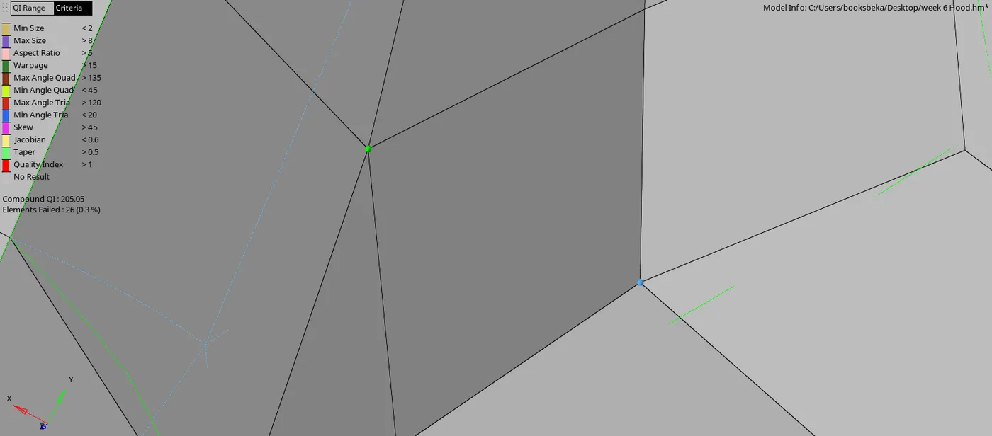
- Using F10,check for the node at which it is failing and use the Distance option.
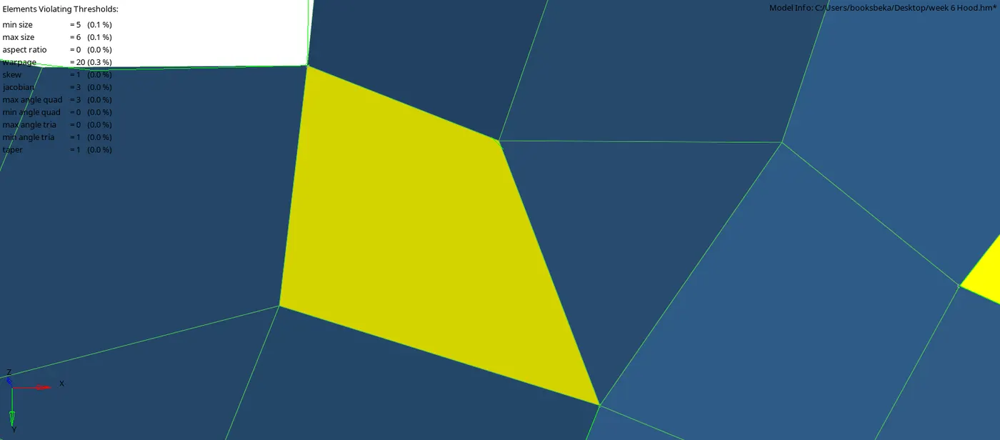
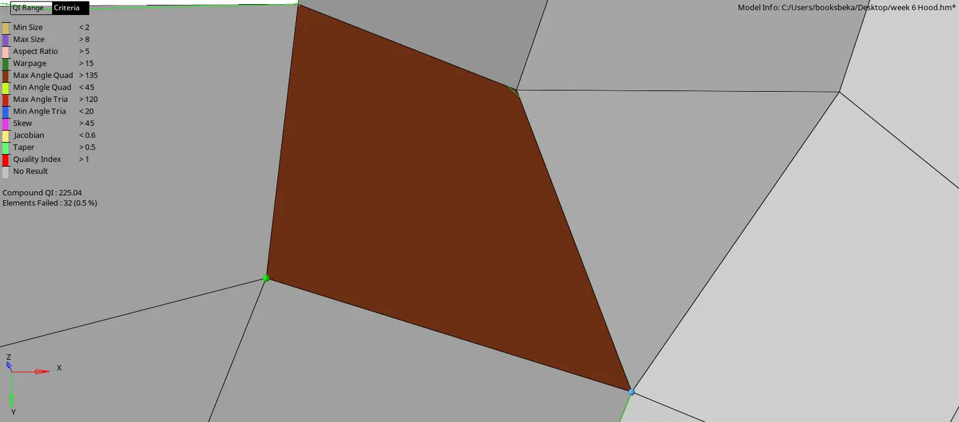
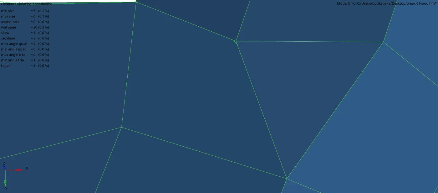
5.6.2. Translate [Shift + F4]
- Tool > Translate > Node > N1, N2 & N3 > Magnitude > Translate +/-
- This option allows us to fix warpages.
- Using F10, check for the node at which we can use the translate option.
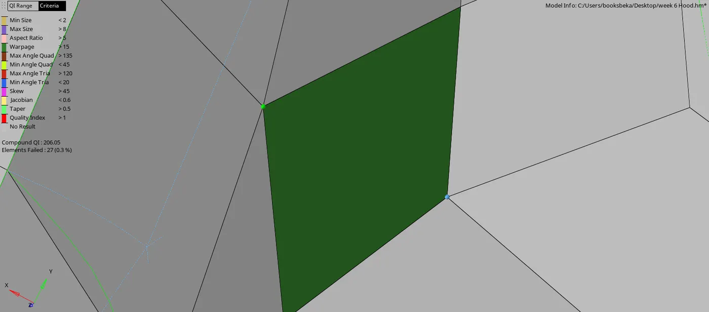
5.6.3. Node Alignement
- In some cases, some nodes may not be aligned with the mesh due to manual clean up operation.
- Inorder to align them, we use Align Node [F7] :
- F7 > Align Node > Select 1st Node > Select 2nd Node > Nodes >Align
- The 1st and 2nd nodes are the source nodes.
Step 6 : Reflect the components
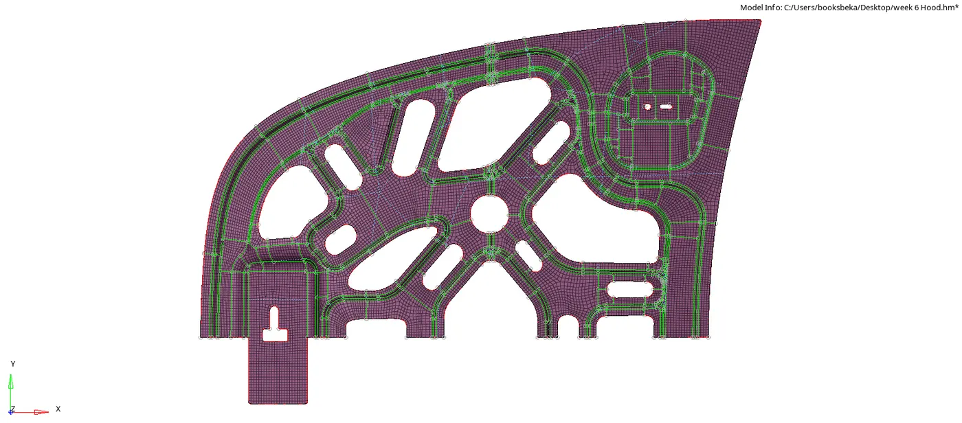
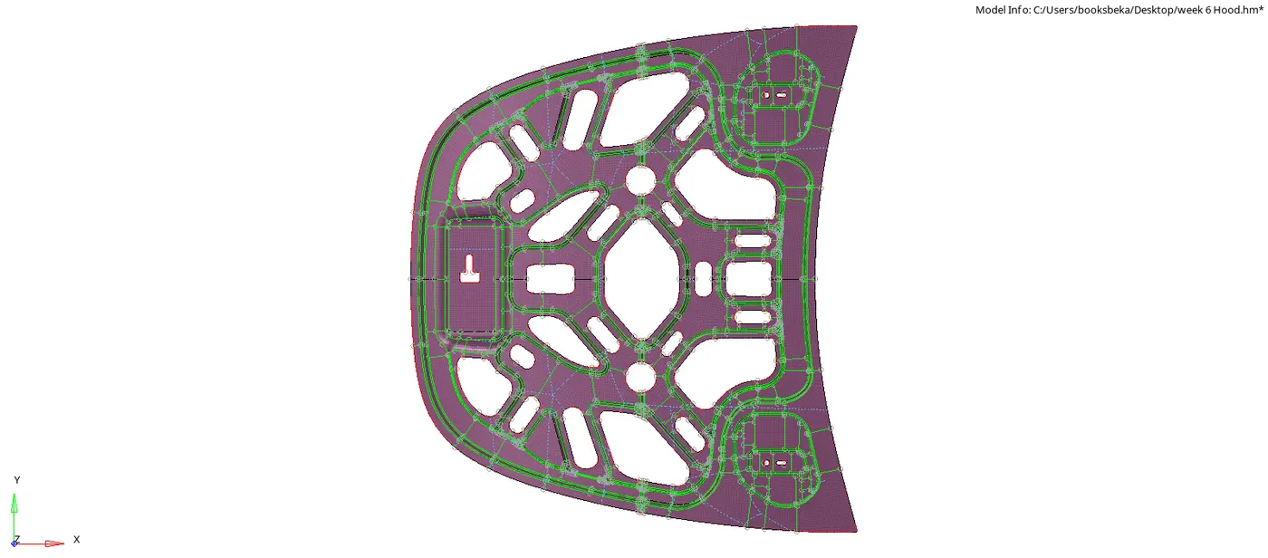
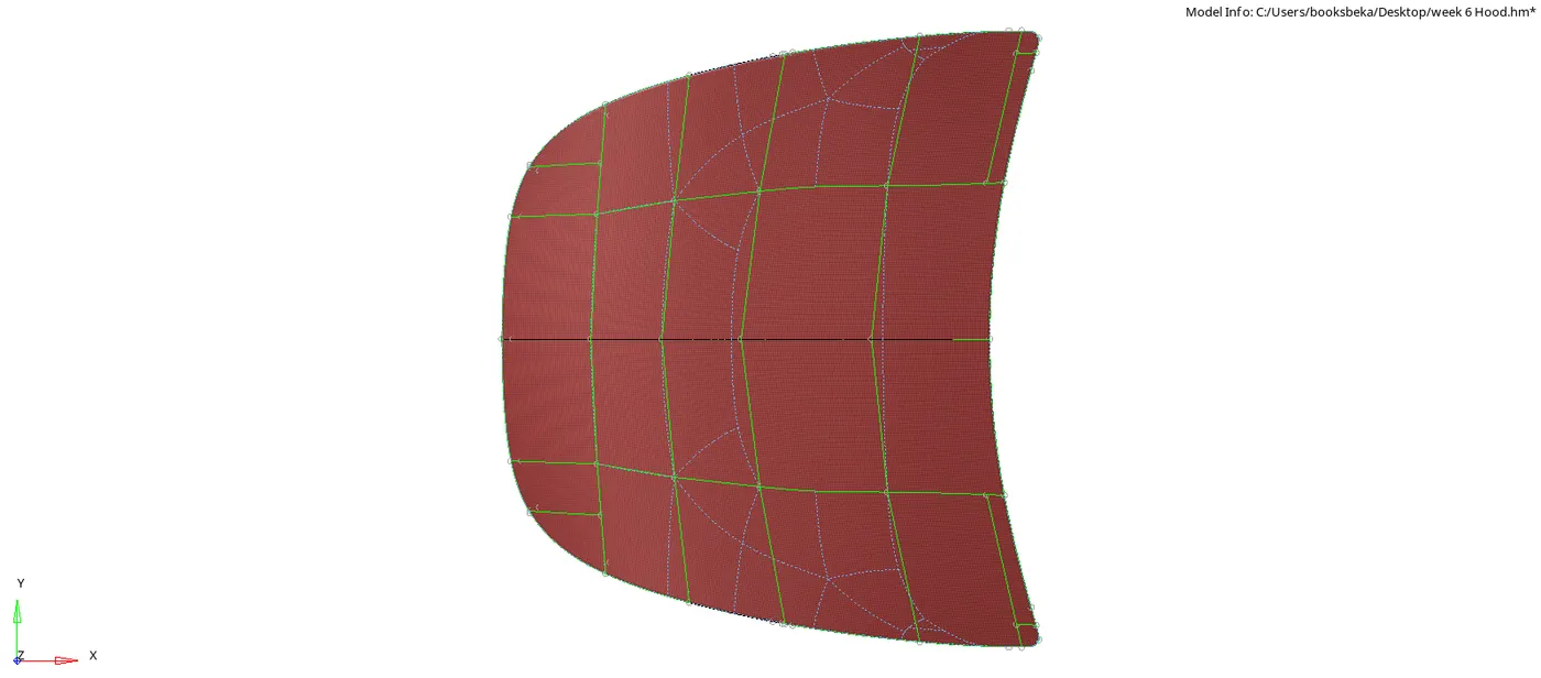
- Reflect the symmetric components (Inner and outer extract)
- Tools >Reflect > Select Elems > Axis of symmetry > Base Node > Reflect
- Once we have reflected for Elements, we can do the same for surfaces.
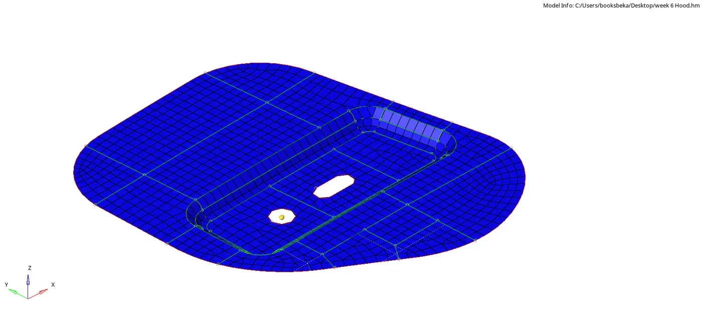
- Reflect the Identical components (Hinges)
- To reflect a component itself along an axis, we need a temporary node as a mid point.
- Geom > Distance > 2 Nodes > Centre distance
- Reflect the component
- Tools > Reflect > Surf (Duplicate > Current Component) > Axis > Base Node
- Target component should be the current component.
- Switch on the surface for both the components.
- To reflect a component itself along an axis, we need a temporary node as a mid point.
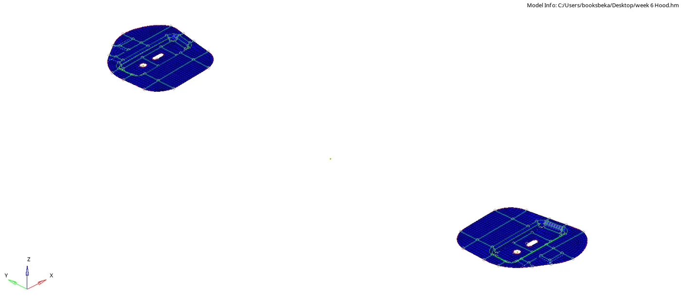
- Once we have reflected, we get the whole finished component.
Result
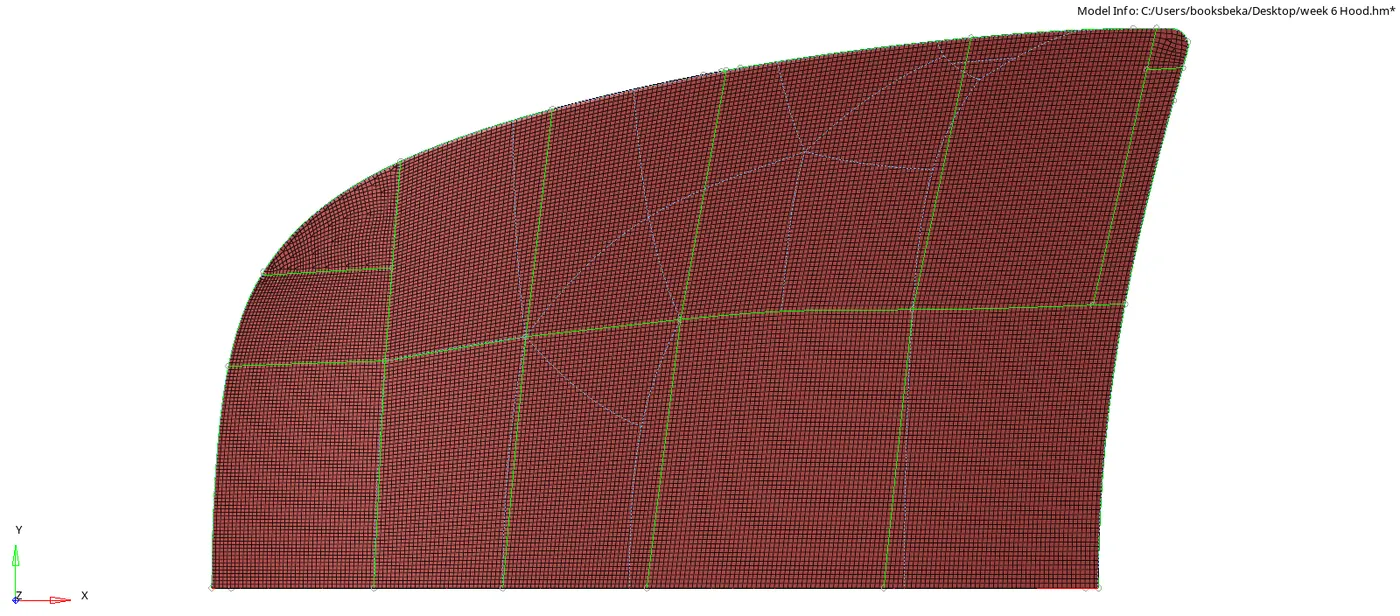
- For the following Parts:
- Latch
- Left Hinge
- Right Hinge
- Inner Extract
- Outer extract
- We have attained :
- Mid surface
- Manual Clean up in mid surface
- Mesh flow maintaining the quality index with zero errors and Tria % under 1 %.
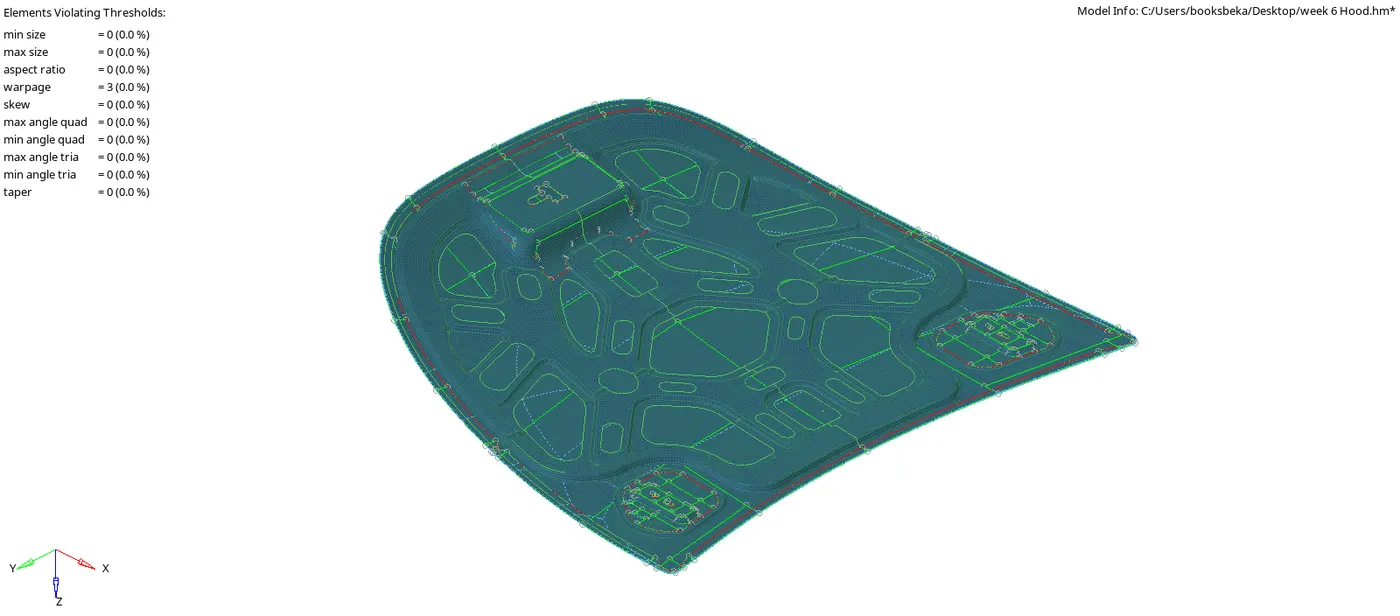

Conclusion with Learning Outcome
I learnt :
- Performing good manual clean up in order to get a good mesh flow.
- How features get captured.
- The Rules for generating a good mesh flow.
- How to generate a good mesh flow using the clean up tools.
- The various shortcuts inorder to save time.
- The importance of performing meshing operation very efficiently to save time.
- Cross check at every stage in order to avoid any mistakes.