Door Applique Design with Engineering Features
OBJECTIVE
Design the Driver Door Right Hand Applique with Locators and Fixtures to assemble it onto the main inner door panel.
LOCATION PRINCIPLE
- The 3-2-1 or 6 Point Location principle is used to constrain the movement of the workpiece (to be machined/fixed) along the 3 axes XX, YY, and ZZ.
- It is achieved by providing 6 pin locations:
- 3 on Base plane.
- 2 on Vertical plane.
- 1 on the plane perpendicular to the first two planes.
- Every object has 12 DOFs and a minimum of 11 should be fixed/arrested.
HEAT STAKING
It is a plastic welding process that joins 2 dissimilar materials (Plastic-Plastic/Plastic-Metal) by controlled melting and reforming.
- The plastic stud protrudes through the hole of the parent that is to be locked with.
- The heated thermal tip contacts the top of the stud at constant pressure and melts it.
- The melted stud fills the volume of the tip cavity to produce the head for locking.
Note: The right combination of Heat and Pressure is required.
Advantages
- Simplification of Machinery.
- Reduces cost of Machinery.
- Multiple fastening points.
- Higher weld density, compared to Hot air Cold form welding or Ultrasonic welding.
PROCEDURE
STEP 1: CHECK CONNECTIVITY
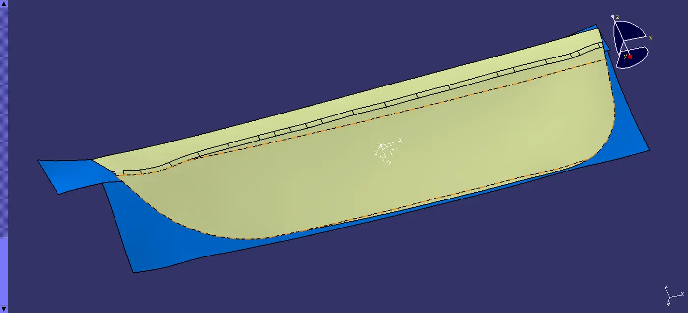
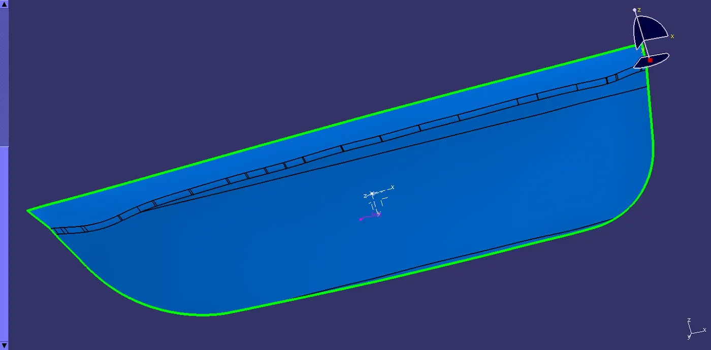
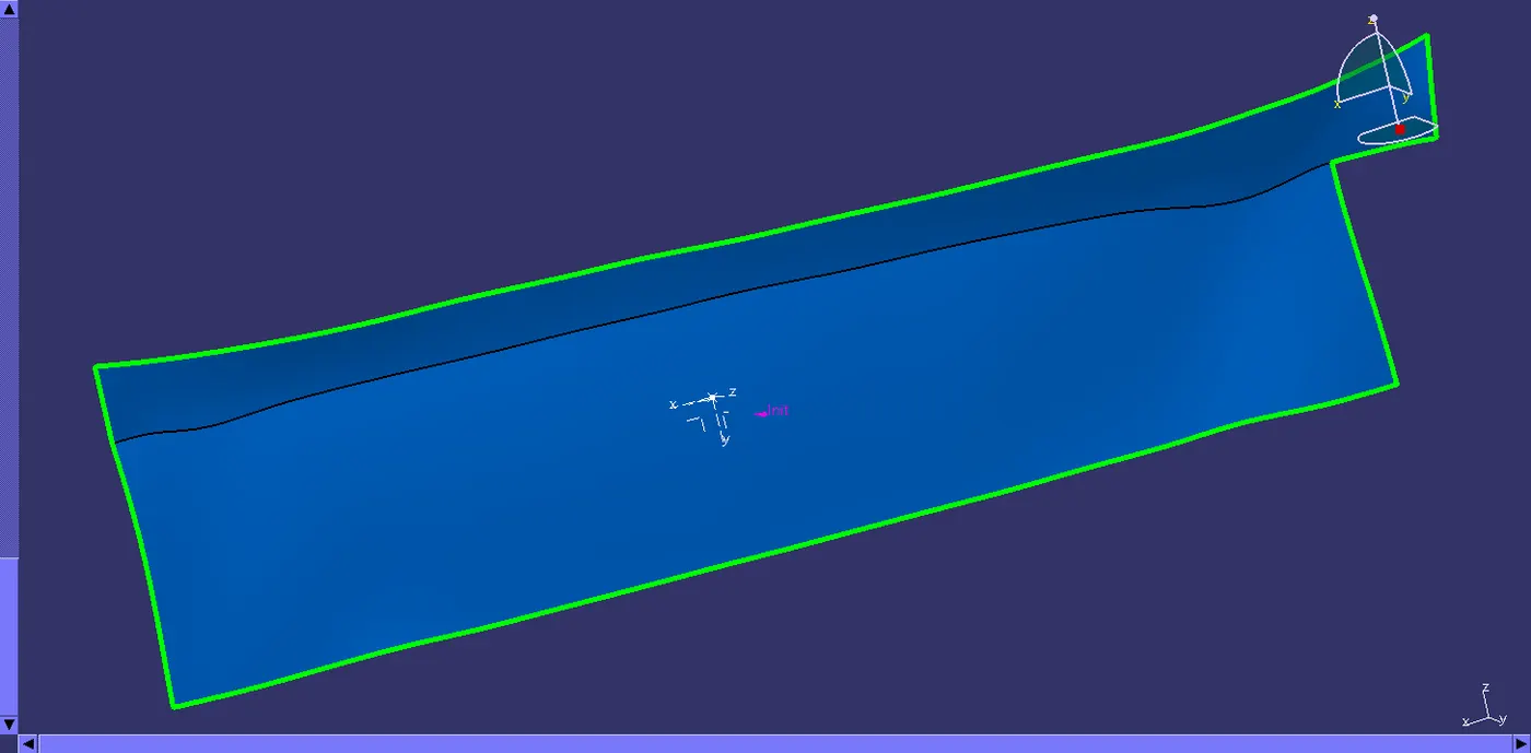
We have to ensure that the Class A Surface is connected as one single profile. We can do that with 2 options:
| Visually | Using the Join option. This option is efficient but not effective. |
| Manually | Extracting the Boundary of the Class A surface. This option confirms better. |
| APPLIQUE | COUNTERPART |
 |
 |
STEP 2: FIND THE TOOLING AXIS
- Tooling Axis is the direction in which the Mold(Core-Cavity) Perpendicular lines always.
- Place the component on each plane (XY/YZ/ZX) and find the desirable tooling direction.
[Note: The plausible tooling axis is perpendicular to a Hole or large flat surface so look for those features when selecting.]
- So we need to create a midpoint on the plane perpendicular to the tooling axis.
| Holes | Use Multiple extracts to get the Boundary and define a midpoint using the "Curve/Circle" option. |
| Flat Surfaces | Extract the surface and then create a mid-point using the "On Surface" option. |
- Now, introduce an Axis system at the Midpoint. This will act as a reference coordinate system.
STEP 4: DRAW THE TOOLING/DRAFTING AXIS
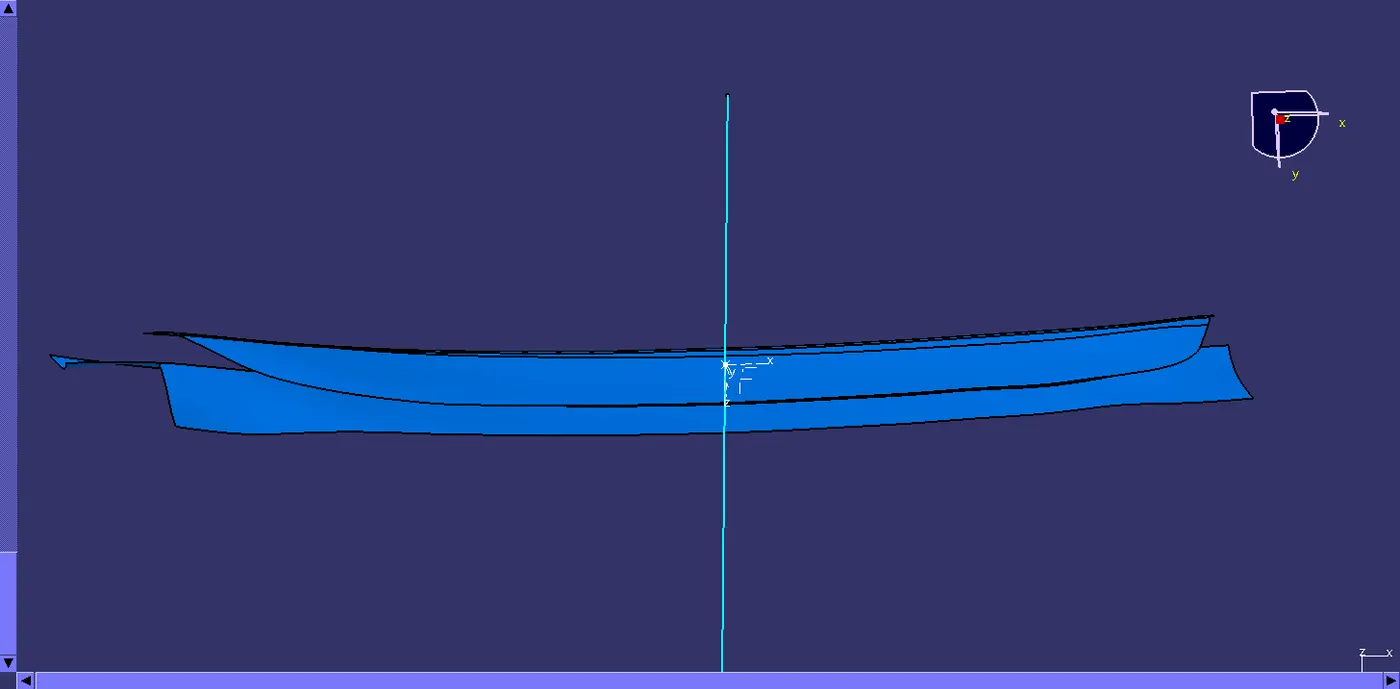
- We employ the Compass method to determine the Tooling axis as it serves to the the most efficient, by saving us time and effort.
- Use the "Measure Inertia" tool to get the Centre of gravity and the co-ordinate system of the selected surface.
- Extend a Line along the Axis that is perpendicular to the surface, that will be our Tooling axis.
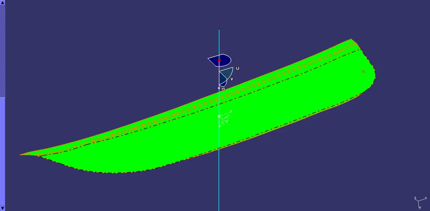
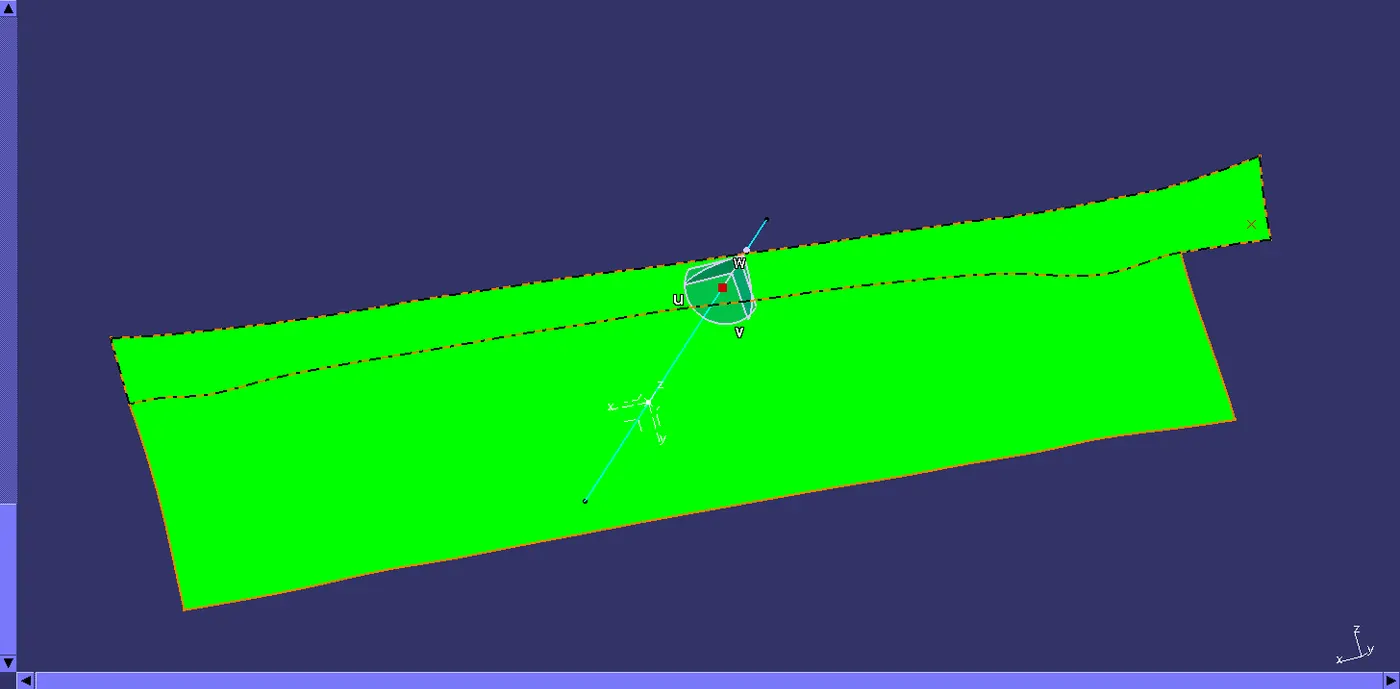
STEP 5: DRAFT ANALYSIS FOR CLASS A
Insert > Analysis > Feature Draft Analysis
Note: Ensure you have the Material view mode ON.
- Define the Draft direction using the "Compass" option.
- Drag the Axis system representation close to the model and align it along the tooling axis.
- "Lock" the Draft direction.
- Set the Colour scale
| Colour | Description | Value |
| Green | Core Side | Above 3 degrees |
| Blue | Parting Line | 0 degrees |
| Red | Cavity Side | Below 0 degrees |
| APPLIQUE | COUNTERPART |
 |
 |
| Method 1: Manual Selection | Method 2: Visual Selection |
|
|
Method 2 is more efficient as it gives us an overall result of the draft analysis without manually picking any feature.
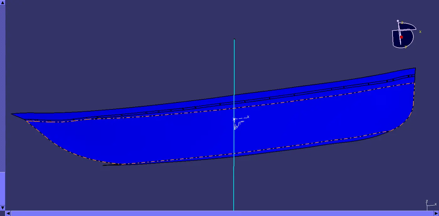
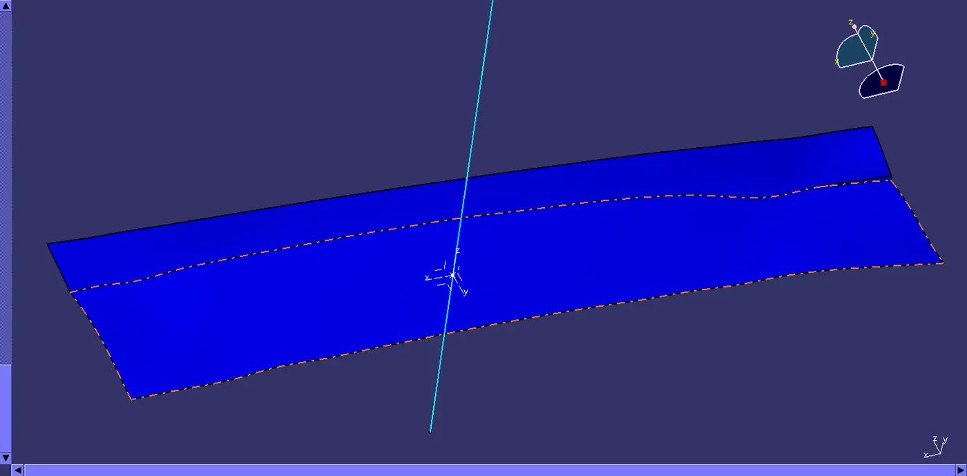
STEP 6: B SURFACE CREATION
Note: Depending on the geometry, the extraction and offset of the fillets might generate non-uniform thickness. So it is advisable to extract only the flat surfaces and then apply fillets at the end of Class B formation.
Perform the following operations in the order:
| EXTRACT | Choose the respective A surface and extract with no propagation option. |
| UNTRIM | The extracted surface will possess the specific trimmed. Untrim to get the basic geometry. |
| EXTRAPOLATE | The surfaces have to overlap each other in order to facilitate trimming therefore extrapolate it up to the required dimension. |
| TRIM | Trim the surfaces according to the required geometry. |
| OFFSET | Now, Offset the Trimmed geometry by the value of the thickness of the component. This Offset is our B Surface. |
| FILLET |
|
Note: The fillet radius of the Class B offset is altered to maintain the uniform thickness throughout the geometry.
| Offset direction | Fillet Radius |
| Inward | Initial Radius - Thickness |
| Outward | initial Radius + Thickness |
| APPLIQUE | COUNTERPART |
 |
 |
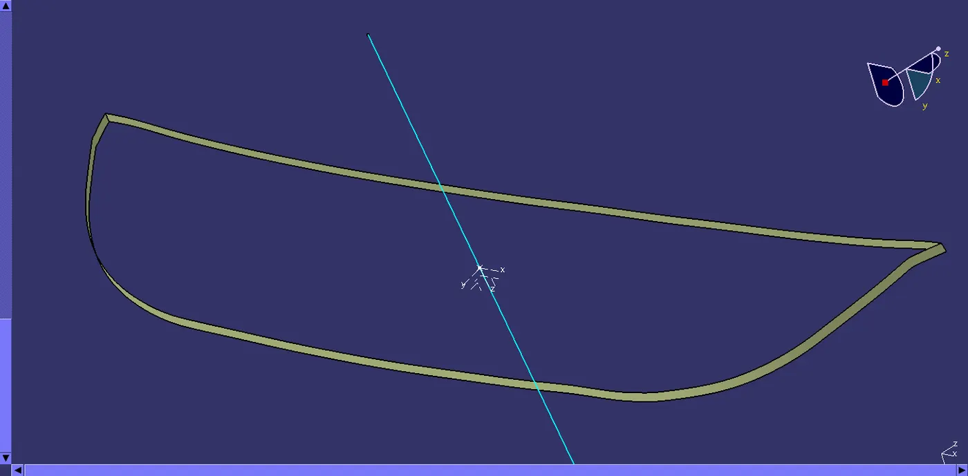
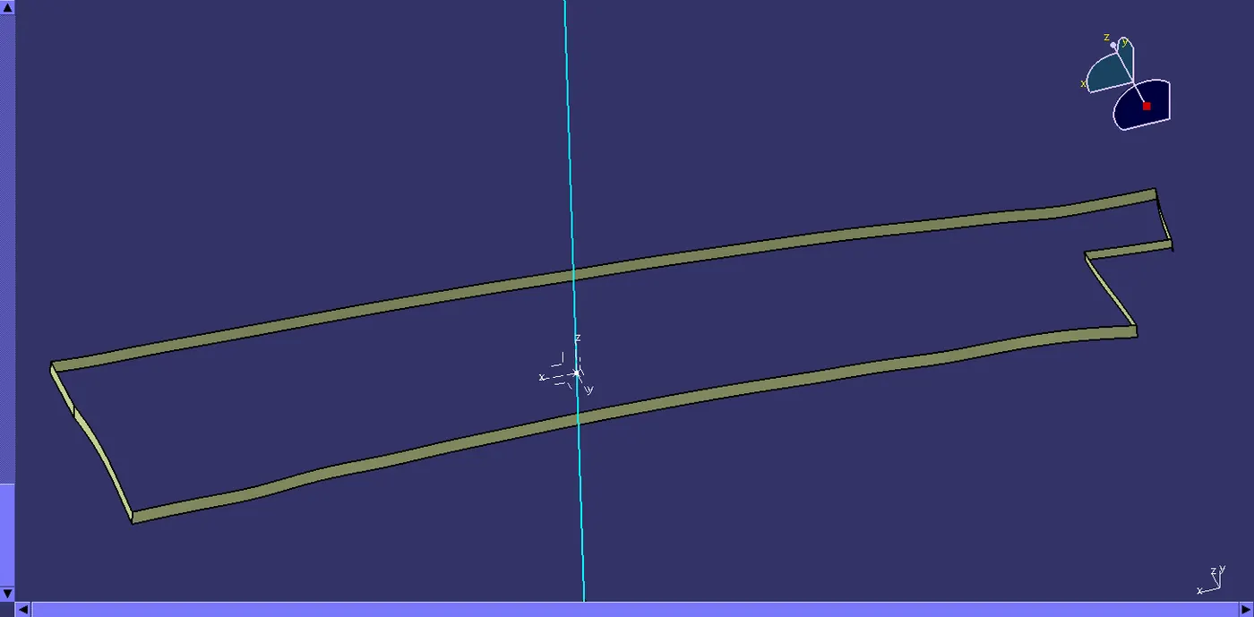
STEP 7: C SURFACE CREATION
C surface is the part of the geometry that connects Class A with B surface.
Rules to be followed. for C surface creation:
- A minimum draft of 3 degrees should be provided to facilitate the Ejection of the Molded component.
- The parting line should be on the B surface. This means that the draft should sweep outwards, from the C surface.
Perform the following operations in the order:
| MULTIPLE EXTRACT | Extract only the Boundary by Tangential selection. |
| CURVE SMOOTH | We need minimum Parting lines as possibles, so smoothen the extracted boundary. |
| SWEEP |
Based on the Geometry of the Coin Holder, the C surface is perpendicular to the tooling axis. Therefore, we Sweep with Reference Surface:
|
| MULTI-SECTIONS SURFACE |
In places like Fillets where the Sweep option doesn't work, we can fill in the gap using MSS.
|
| EXTRAPOLATE |
|
| TRIM |
To get a clean edge/corner we have to Trim the overlapping edges. |
| JOIN | For our future reference, we can Join all the C surface sweeps as one single entity. |
| APPLIQUE | COUNTERPART |
 |
 |
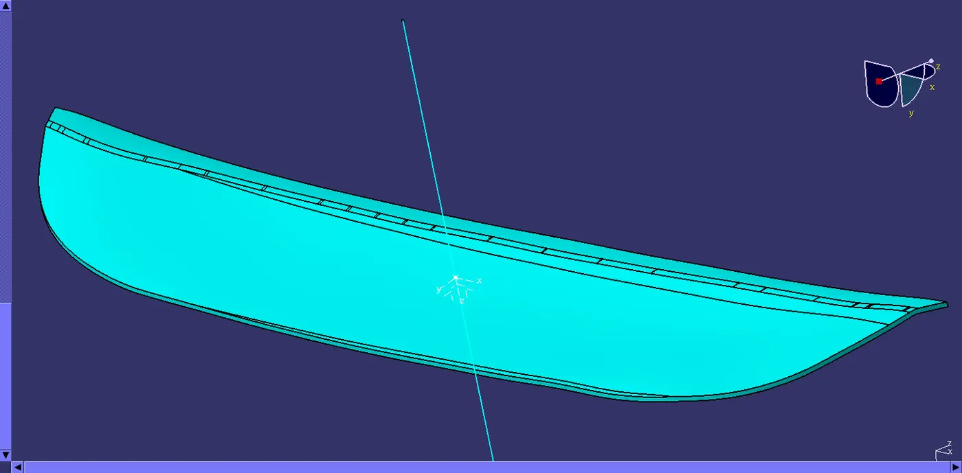
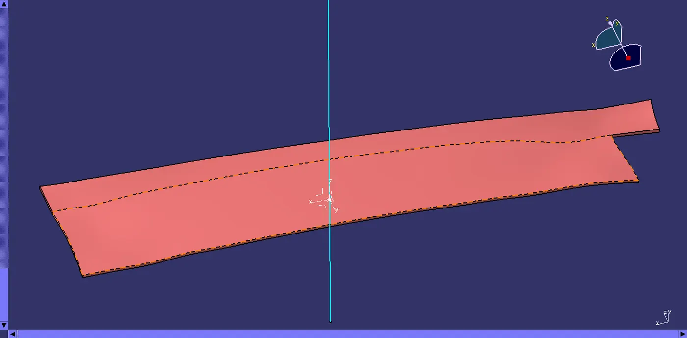
STEP 8: TRIM THE SURFACES A, B & C
- First Trim/Join Class A with Class C.
- Then Trim with Class B and keep the respective surfaces.
| APPLIQUE | COUNTERPART |
 |
 |
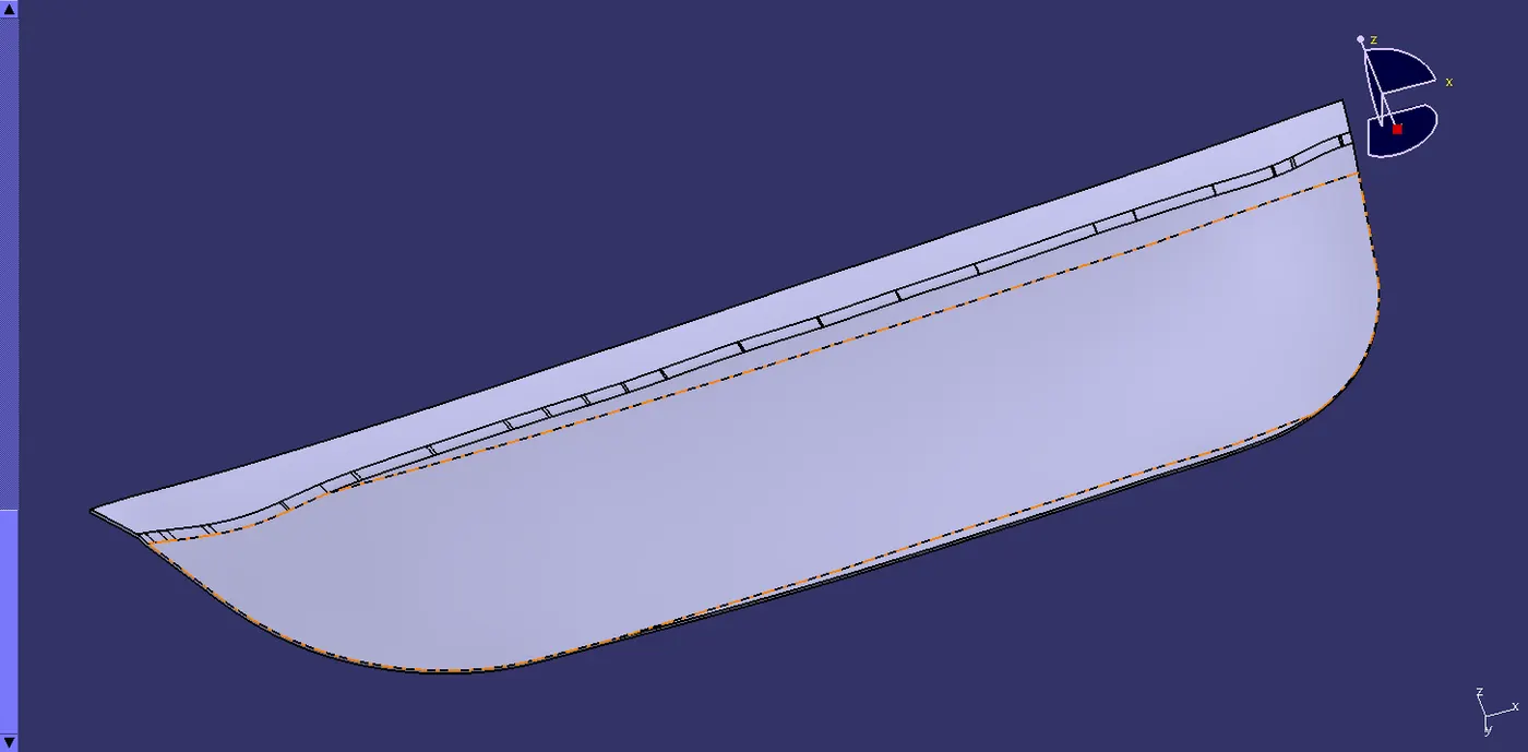
STEP 9: CLOSED BODY
- Switch to Part Workbench.
- Define the part body.
- Select the closed surface trim to fill it with volume.
- Now we have a solid body with a certain volume and density (depending on the material we give).
STEP 10: CLOSED BODY DRAFT ANALYSIS
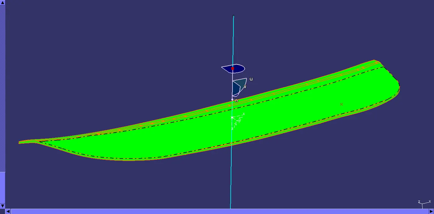
All the 3 class surfaces must pass in this analysis.
Insert > Analysis > Feature Draft Analysis
Note: Ensure you have the Material view mode ON.
- Define the Draft direction using the "Compass" option.
- Drag the Axis system representation close to the model and align it along the tooling axis.
- "Lock" the Draft direction.
- Set the Colour scale
| Colour | Description | Value |
| Green | Core Side | Above 3 degrees |
| Blue | Parting Line | 0 degrees |
| Red | Cavity Side | Below 0 degrees |
| APPLIQUE | COUNTERPART |
 |
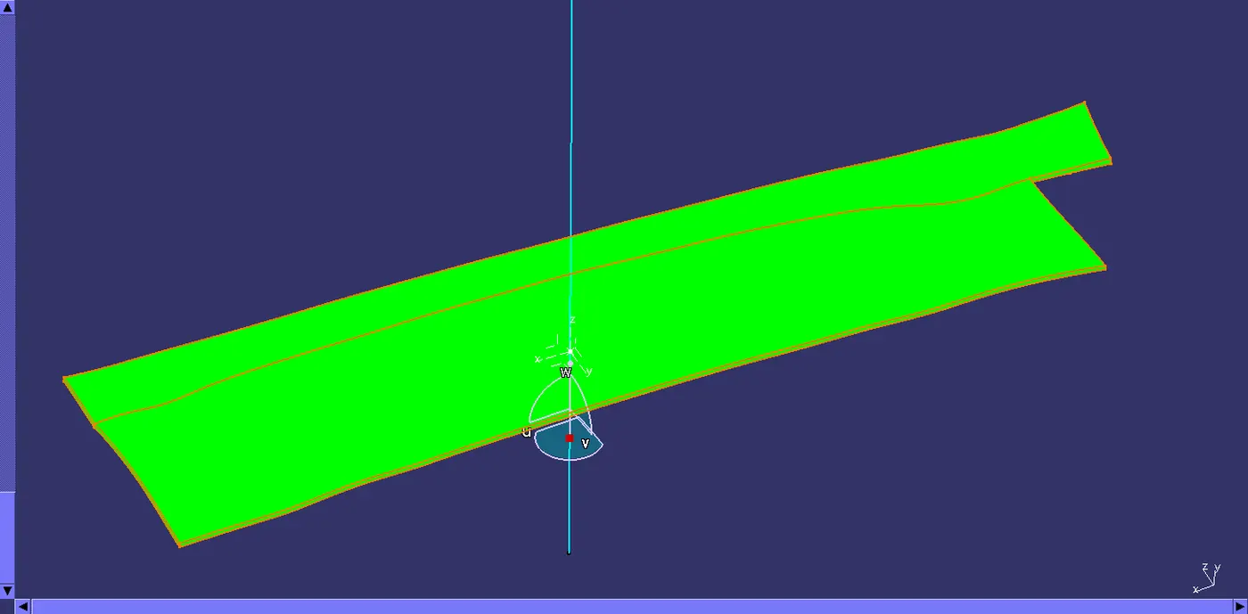 |
- Place the Analysis Tool (Arrow Icon) anywhere on the model and review the colours on the feature.
- If any feature (especially C surface) is showing Blue/Red then choose the same option again (It will switch to Analysis under Running point) and place on the respective feature to review the deviation of the sweep angle from the Tooling Axis.
STEP 11: OPERATIONS PERFORMED
| Extrude |
|
| Thickness |
|
| Draft |
|
| Boolean |
|
| Fillet |
|
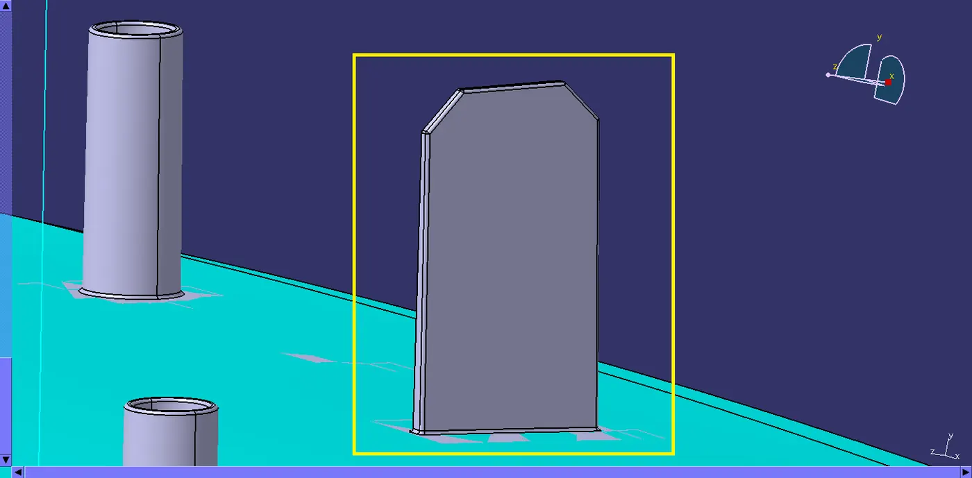
11.1 LOCATORS
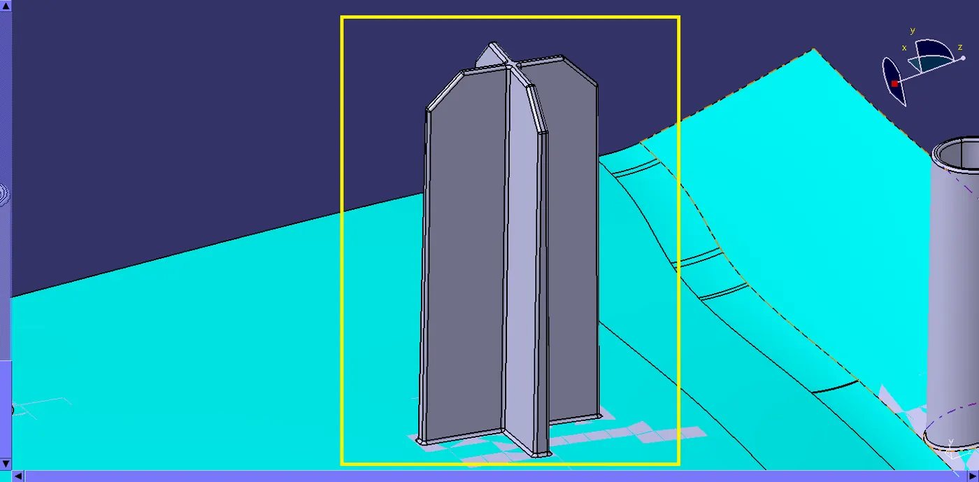
- We have to design the 3-2-1 location principle to arrest the applique onto the inner door panel.
- Therefore, we employ:
| Type of Locator | Quantity |
| 4 Way Pin | 2 |
| 2 way Pin | 1 |
- No. of DOFs arrested = 11.
11.1.1 DESIGN GUIDELINES FOR 4 WAY AND 2 WAY LOCATORS
| Draft |
|
| Thickness |
|
| Fillet |
|
| Height |
|
| Base Rib Root Dia |
|
| Spacing between Ribs |
|
| 4 WAY LOCATOR | 2 WAY LOCATOR |
 |
 |
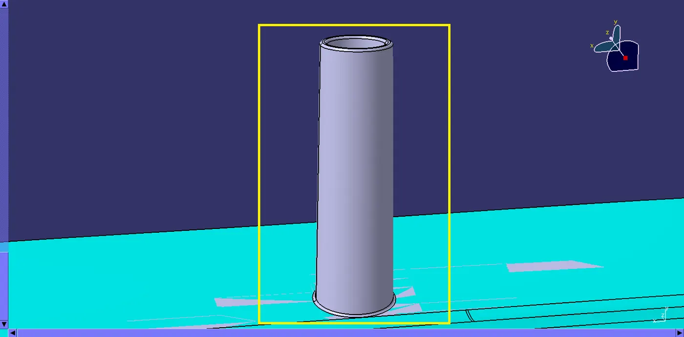
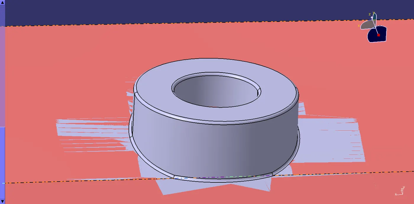
11.2 HEAT STAKES
The guidelines for Heat stakes are given below:
| Diameter |
|
| Thickness |
|
| Height |
|
| Draft |
|
| Flat plate |
|
| Clearance |
|
| Spacing |
|
| HEAT STAKE | FLAT PLATE |
 |
 |
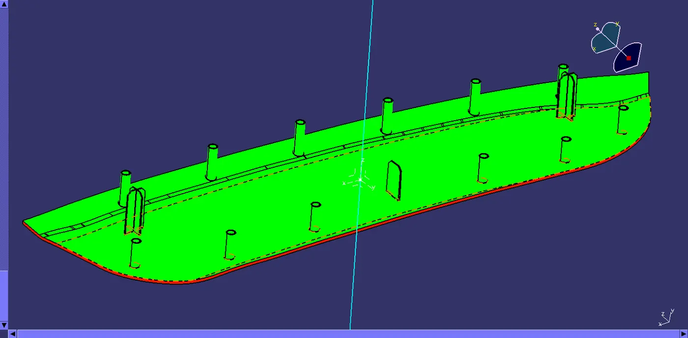
STEP 12: FINAL DRAFT ANALYSIS
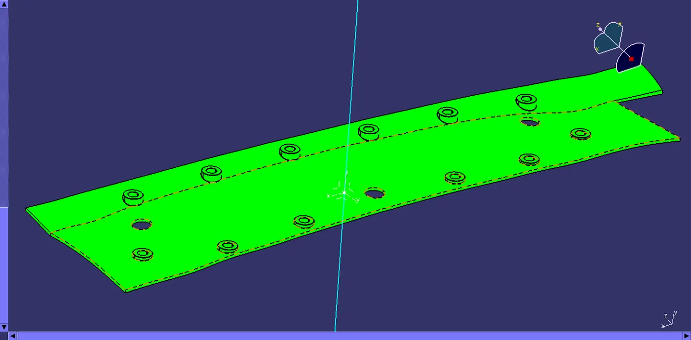
All the Heatstakes, 2 way and 4 way pins must pass the draft analysis.
Insert > Analysis > Feature Draft Analysis
Note: Ensure you have the Material view mode ON.
- Define the Draft direction using the "Compass" option.
- Drag the Axis system representation close to the model and align it along the tooling axis.
- "Lock" the Draft direction.
- Set the Colour scale
| Colour | Description | Value |
| Green | Core Side | Above 0.5 degrees |
| Blue | Parting Line | 0 degrees |
| Red | Cavity Side | Below 0 degrees |
- Place the Analysis Tool (Arrow Icon) anywhere on the model and review the colours on the feature.
- If any feature is showing Blue/Red then choose the same option again (It will switch to Analysis under Running point) and place on the respective feature to review the deviation of the sweep angle from the Tooling Axis.
| APPLIQUE | COUNTERPART |
 |
 |
RESULT
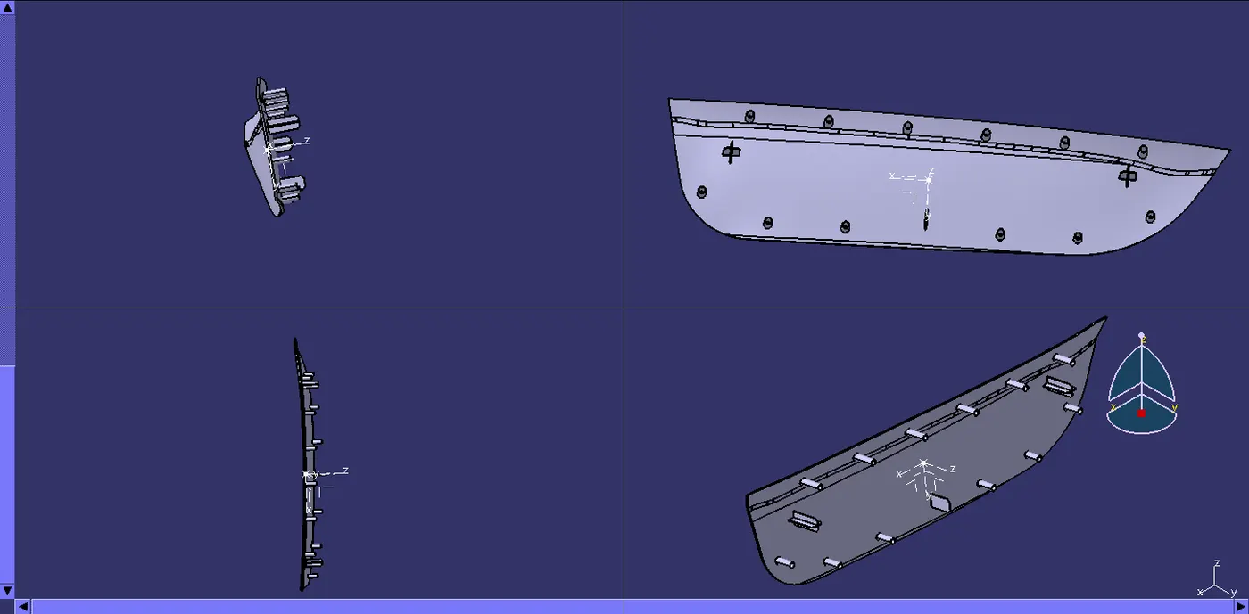
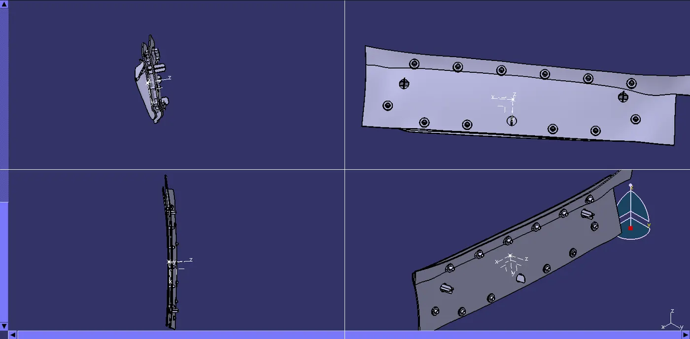
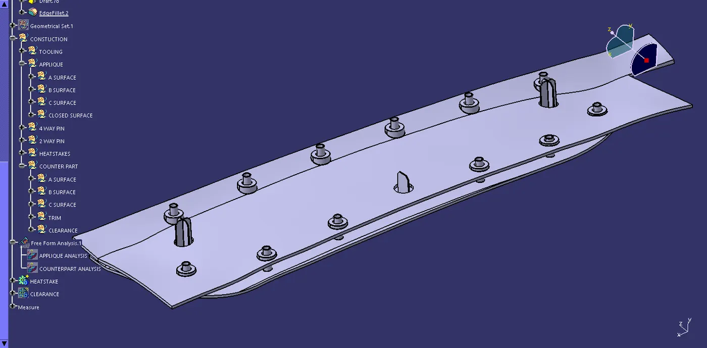
- The Driver Door Right Hand Applique is designed with the features listed below, following the design guidelines:
- 4 way locators
- 2 way locator
- Heatstakes
- The DOFs are arrested in 11 directions, allowing the applique to assemble onto the inner door panel.
|
APPLIQUE: FIRST ANGLE PROJECTION |
 |
|
COUNTERPART: FIRST ANGLE PROJECTION |
 |
|
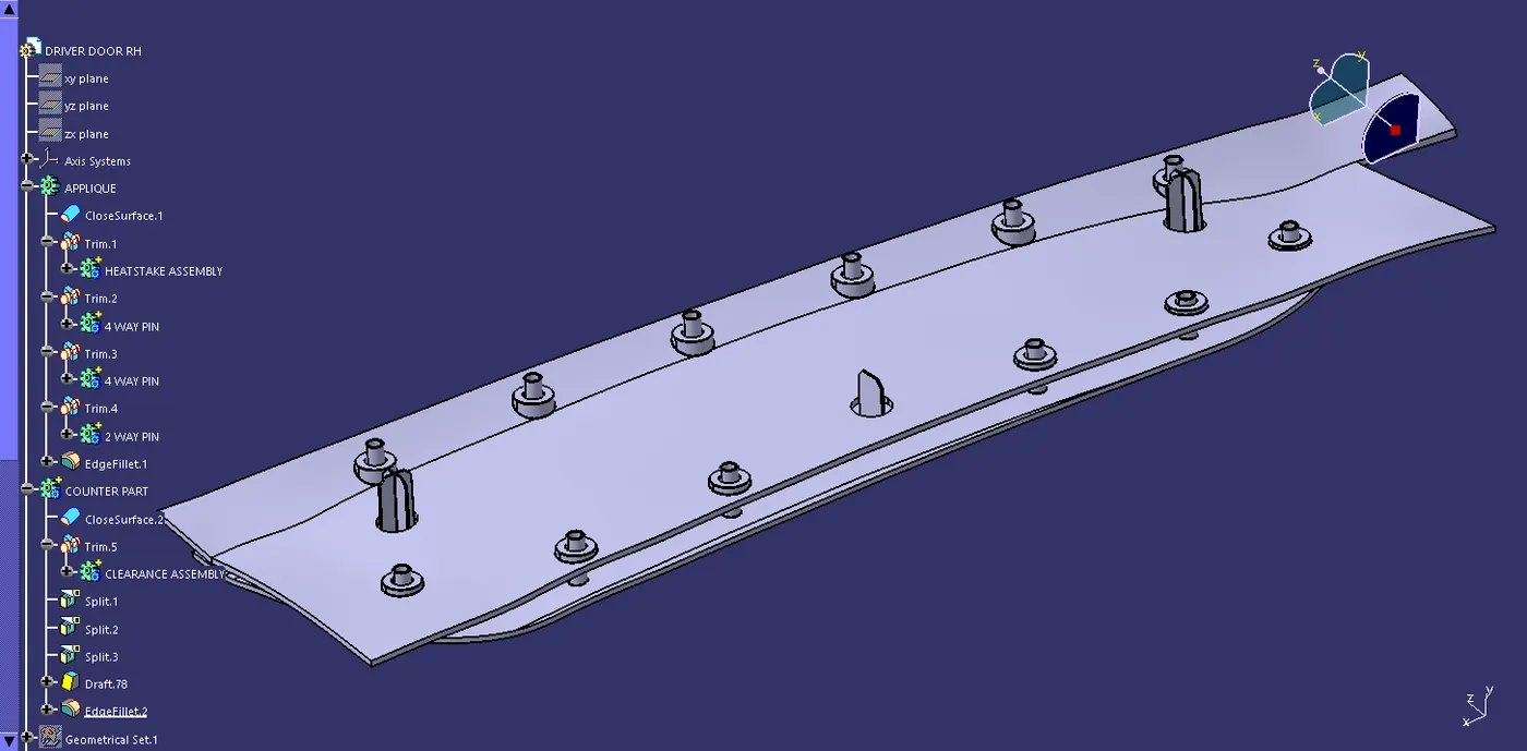
TREE STRUCTURE: PART WORKBENCH OPERATIONS |
 |
|
TREE STRUCTURE: SURFACE WORKBENCH OPERATIONS |
 |