Assembling, Connecting and Debugging of Rail Components using Hypermesh
Objective
- To assemble the components with the respective connectors.
- All the connectors should get realized.
- Perform debugging if required.
- After connecting, the mesh flow should be free of distortions.
Procedure
Step 1: Importing
Since we are importing a CAD geometry, the format will be either of the 2 industrial accepted standards:
- STEP (Standard for the Exchange of Product data).
- IGES (Initial Graphics exchange specification).
- When selecting the file for import, be sure to check if it is .stp or .igs.
- File > Import > Import Model > File type > Open File > Import File
- We only have to work on the geometry, so before inspection check for solids and delete if there are any.
- Delete [F2] > Solids > Displayed > Delete Entity
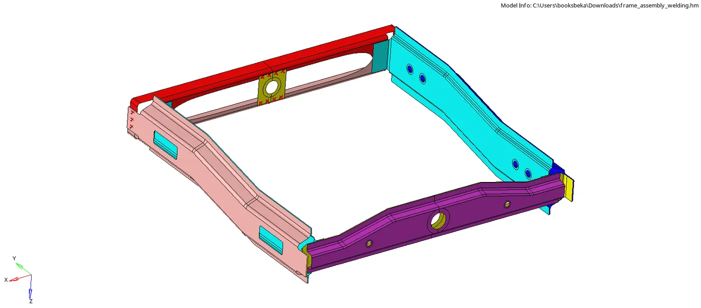
Step 2: Inspection
2.1. Check for the number of components
Upon initial inspection, we can see that there are 9 geometries :
- Front Truss 1
- Front Truss 2
- Right Rail 1
- Right Rail 2
- Left Rail 1
- Left Rail 2
- Rear Truss 1
- Rear Truss 2
- Reinforcement plate
2.2. Organize the components
- It is not possible to learn which component is which in the short time that we have to create connections.
- Also, it is not efficient to look for the desired component by checking the surfaces on/off in the tab bar for all the components one by one.
- There are 2 ways to isolate a model and work on it:
- Isolate shown
- Selector
2.2.1. Isolate shown
- Why we use Isolate shown?
- When we want to directly access the component from the tab bar without selecting and deselecting all the components.
- When we know the name of the component to work on but not the geometry.
- The option is present in the Tab bar right below the search Menu.
- Isolate shown > Click on the Component ID > Component is displayed on the GUI
- Upon following the above step, only the selected component will be shown and the rest will be hidden.
2.2.2. Selector
- We use Selector for:
- When we want to directly access the component from the GUI.
- When we know the geometry to work on but not the component ID.
- The option is present in the Tab bar right below the search Menu:
- Selector > Click on the Component in the GUI > Component is displayed on the GUI
- Upon following the above step. only the selected component will be shown and the rest will be hidden.
2.2. Check for Geometric Errors
- We just have to check for surface deformations if any.
Step 3: Create Assemblies
[Note: This step is optional]
- As we are working on different connections with different combinations of components, it is time-consuming to go back and forth and select the components individually.
- We can create assemblies based on the connectors used between the components.
- For example, in the challenge, the first connector is Seam-Quad(angled+capped+L) between Right Rail 2 & Front Truss 1.
- We create an assembly and assign the above components to it.
- Steps to be followed to create an assembly:
- Tool > Assemblies > Create > Assem name = ______ > Card Image = 1 > Comps (Select) > Create
- In future, it will be easier to access the components and the respective connector by just clicking at the assembly.
Step4: Manual Cleanup
- Not much manual cleaning up is actually required for this model.
- But some of the components have holes, in order to get a good mesh flow we have to create washer splits around them.
- Washer split allows us to create a shared edge (green line) around the hole (a free edge - red line) by a certain offset value.
- We create washer split to avoid any trias at free edges and to maintain a good mesh flow around the holes.
- Step to follow to create washer splits is mentioned below:
- Geom > Quick edit [F11] > Washer split > Give Offset value > Middle Click
- From inspection, we can observe that washer splits are already present. Hence, we don't skip to the next step.
Step 5: Meshing
- Mesh size = 6 mm
- We are not worried about any element quality so we can directly mesh the component.
- 2D > Automesh > Surfs > Elem size = 6mm > Mesh Type : Mixed
- Check the tick boxes for Flow and size to get a good flow.
- Upon giving for mesh, we have an option to alter the mesh density if needed.
Step 6: Establishing Connections
6.1. Right_Rail_2 & Front_truss_1:- Seam-Quad(angled+capped+L)
- We can select the components using either of the 3 steps:
- Isolate shown (refer 2.2.1)
- Selector (refer 2.2.2)
- Select Assembly_1 from tab bar (refer step 3)
- Steps to perfrom Seam weld:
- 2D > Connectors > Seam > Location : NodeList (Select by Node path) > Connect what : Comps (select) > Tolerance = 10mm Type: "Seam-Quad(angled+capped+L)" > Quad Transition > Imprint > Create
- Loaction spefies the nodes at which the seam welding is done.
- Connect what specifies the components that we have to seam weld.
- When we give a Tolerance value, Hypermesh will search for any neighbouring nodes within the circular radius of that tolerance limit.
- Quad transition depicts the type of mesh flow we wish to follow, in our case quads.
- Imprint is used for simple components

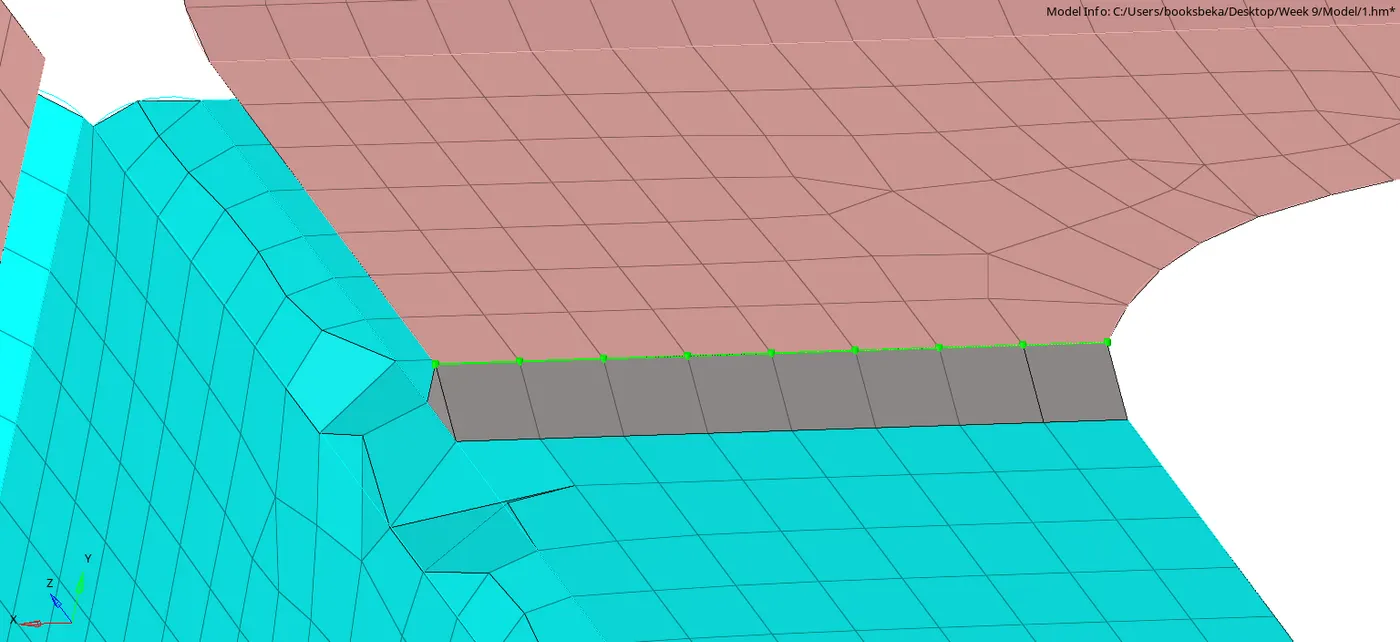
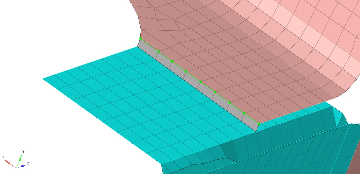
6.2. Left_Rail_2 & Front_truss_1:- Quad elements
- The steps are very similar to seam welding:
2D > Connectors > Seam > Location : NodeList (Select by Node path) > Connect what : Comps (select) > Tolerance = 10mm Type: "Quads" > Quad Transition > Imprint > Create

6.3. Front_truss_2, Front_truss_1 & Right_Rail_1:- Spot weld with 3 Layers and 5 mm Diameter
2D > Connectors > Spot > Location : NodeList (Select by Node path) > Connect what : Comps (select) > Tolerance > 10 > Type: Weld > Number of layers = 3 > Diameter =5mm
> Create
- Number of Layers depicts the number of surfaces to be spot weld, in our case it is 3.
- No Property means that a flat element (2D) will be used. There won't be any load transfer.

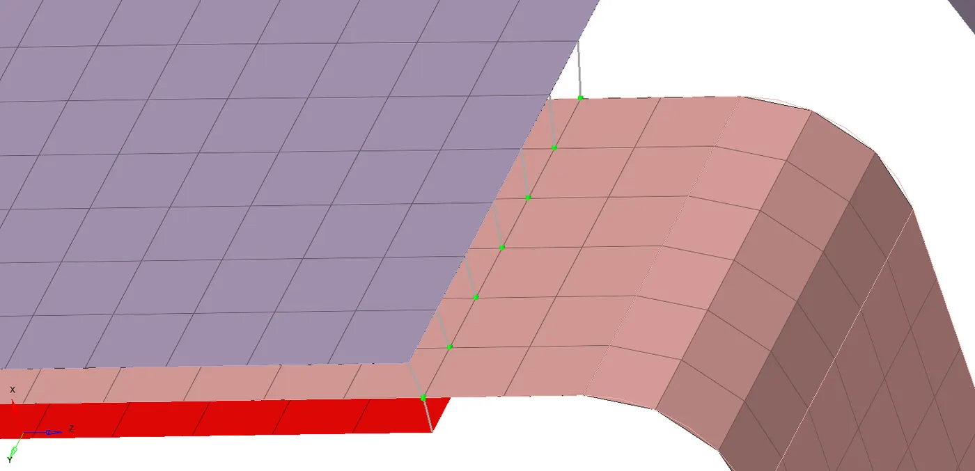
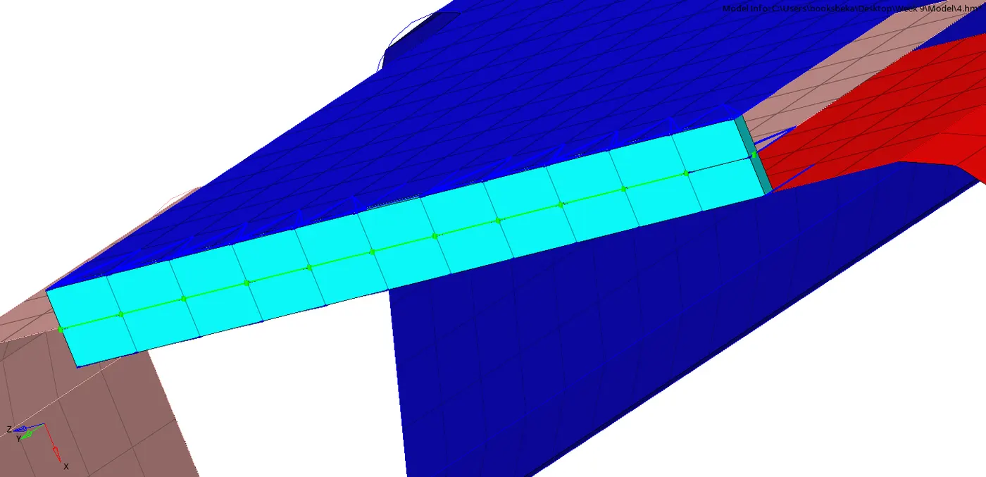
6.4. Front_truss_2, Front_truss_1 & Left_Rail_1:- Hexa (Adhesive)
- Hexa (Adhesive) is available under seam panel.
- 2D > Connectors > Seam > Location : NodeList (Select by Node path) > Connect what : Comps (select) > Tolerance = 10mm > Type: Hexa (Adhesive) > Strips = 1 > Coats = 1 > Width =1 > Create
- Adhesive uses RBE3 elements as RBE2 is infinitely stiff.
- Strips depict the Thickness.
- Coats depict the Width.

6.5. Rear_truss_2 & Right_Rail_2:- Bolt Connector
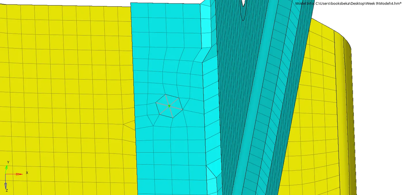
- 2D > Connectors > Bolt > Location : NodeList (Select by Node path) > Connect what : Comps (select) > Tolerance = 10mm > Create
- Before creating bolt, enter the following parameters from within the spot weld module:
-
- Tolerance = 10mm
- Type: Bolt (general)
- Create hole, if none > Create
- Since there are no holes to make a bolt connection we have to create a hole using "Create Hole, if none option"

6.6. Rear_truss_2 & Left_Rail_2:- Bolt Connector
The procedure is the same as the previous step (6.5).
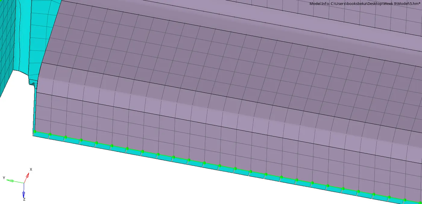
6.7. Right_Rail_1 & Right_Rail_2:- Spot-weld with Rigid Elements
- 2D > Connectors > Spot > Location : NodeList (Select by Node path) > Connect what : Comps (select) > Type: Weld > Create
- Before creating weld, enter the following parameters from within the spot weld module.
- Tolerance = 10mm
- Number of layers = 2

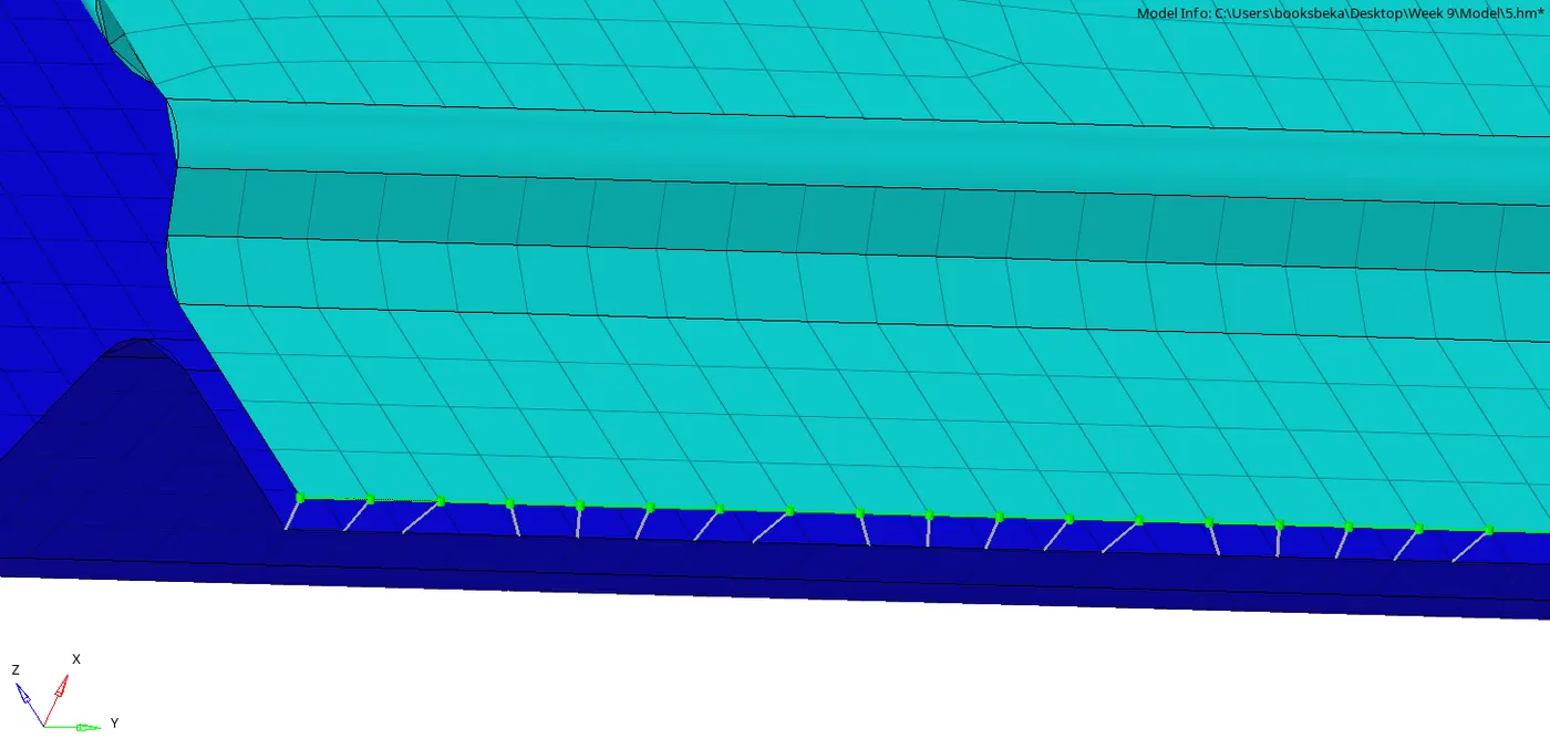
6.8. Left_Rail_1 & Left_Rail_2:- Spot-weld with Spring Elements
- 2D > Connectors > Spot > Location : NodeList (Select by Node path) > Connect what : Comps (select) > Type: Spring > Create
- Before creating spring, enter the following parameters from within the spot weld module.:
- Tolerance = 10mm
- Number of layers = 2

Result
The Components are joined using the respective connectors:
1. Right_Rail_2 & Front_truss_1: Seam-Quad(angled+capped+L)
2. Left_Rail_2 & Front_truss_1: Quad elements
3. Front_truss_2, Front_truss_1 & Right_Rail_1: Spot weld with 3 Layers and 5 mm Diameter
4. Front_truss_2, Front_truss_1 & Left_Rail_1: Hexa (Adhesive)
5. Rear_truss_2 & Right_Rail_2: Bolt Connector
6. Rear_truss_2 & Left_Rail_2: Bolt Connector
7. Right_Rail_1 & Right_Rail_2: Spot-weld with Rigid Elements
8. Left_Rail_1 & Left_Rail_2: Spot-weld with Spring Elements
9. Remaining components are joined with suitable connectors.
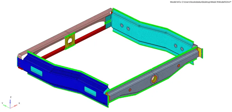
- The Mesh flow remains free of any distortions after connecting.
- The Railed connectors (Red) were fixed.
- All the connectors are Realized (Green). We can view them in the Tab bar.
Conclusion with Learning Outcome
I learnt :
- The significance of using connectors in Pre-processing.
- How to join components using Connectors.
- How to debug Connectors.
- How to choose the appropriate connector for different geometries and conditions.
- To work on different types of connectors, such as:
- Welds
- Bolts
- Adhesives, etc.
- Physical characteristics for seam welding, such as:
- Weld angle
- Height
- Cap Angle
- Runoff angle