Week 8 - Challenge 2 - Base Bracket Design
CREATION OF TOOLING AXIS AND DRAFT ANALYSIS FOR PLASTIC BASE BRACKET
Objective:
The main objective of this project is to create the tooling axis and the draft analysis for the Plastic base bracket using Catia V5.
Introduction:
The tooling axis is very important for the component to be manufactured, keeping that tooling axis as reference the part can be manufactured without any congestion and will ease the way in manufacturing the part. The draft analysis will show the important angles of the body, it is very important to maintain positive draft angle.
Methodology/approach:
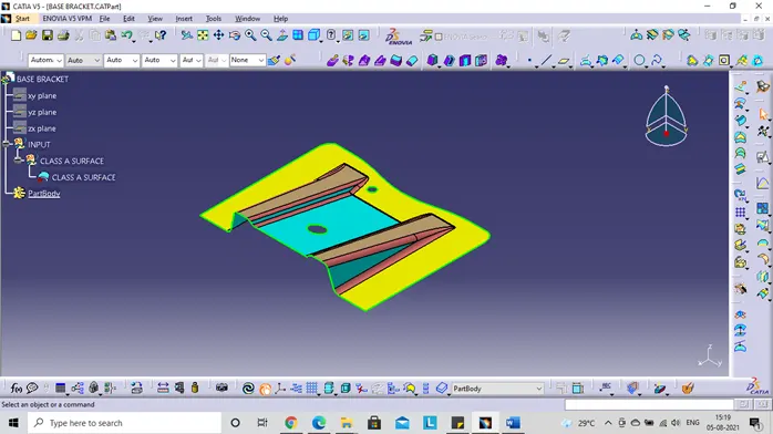
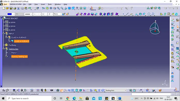
- For the creation of tooling axis and draft analysis, the first important input is the class A surface, then further using Catia V5, create the tooling axis and draft analysis, first, check the best direction (X, Y, Z) and select the direction at which is very easy to manufacture. Z direction is selected for the Tooling axis. Create the dummy tooling axis in Z direction keeping the point as reference.
- Create a plane in ZY direction on the reference point and then create an intersection curve of ZY plane of the base bracket. To get the bisecting line of the two line at an angle, create two lines and bisect them to get the tooling axis.
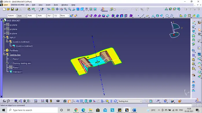
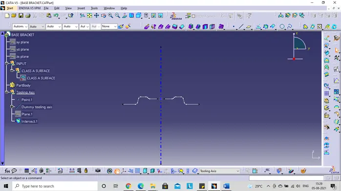
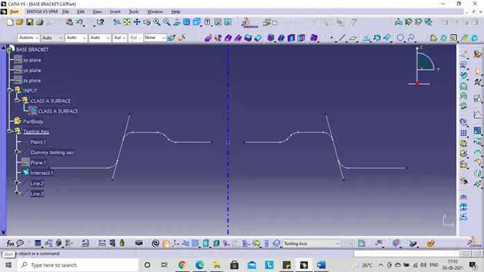
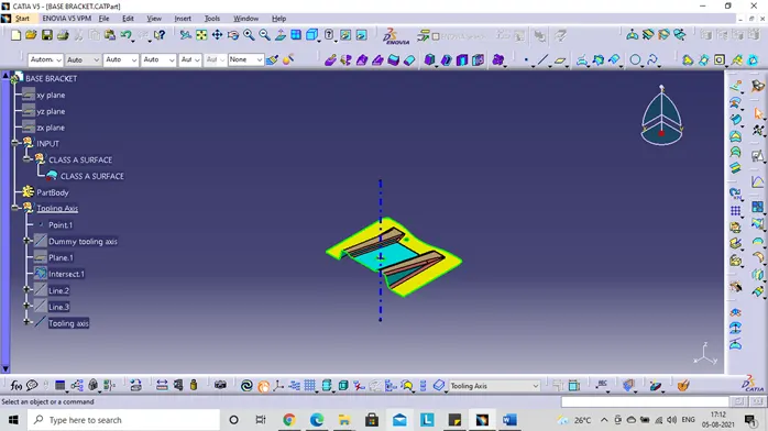
- Then, use the feature draft analysis to check the draft analysis of the base bracket using the tooling axis
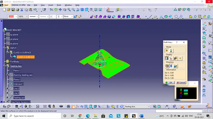
- Use the analysis>Feature draft analysis toolbar to check the draft analysis, Use the compass and place in the Z direction line being upwards and lock it.
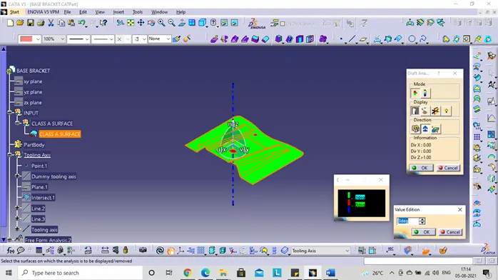
- Select the axis and the part so that the color changes according keeping the reference as tooling axis.
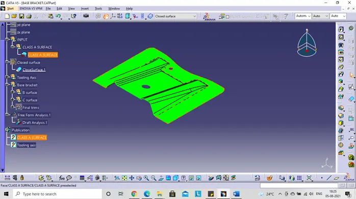
- On the quick analysis mode there are 3 colors green, red and blue. We can change the values as per our standards, it is good to main standard drafting angles 0 to 3 degrees
- Analysis on running point - with the help of this option, the angles at every point can be checked easily.
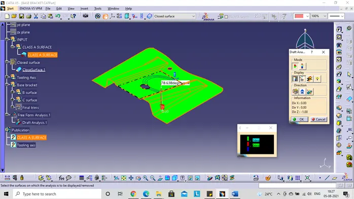
- Publishing – Use the publish option to publish the Fan cover and the tooling axis, so to obtain the draft analysis of the part.
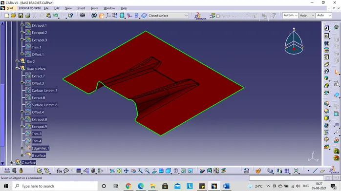
- Thicken the base bracket using some of the surface features, since the edge fillet has to be at equal distance on the offset surface, we add the thickness for the edge fillet, the final offset will be the B surface
- The C surface is the surface which gives the draft angle to the thickened body, using the tooling axis we can obtain the C surface
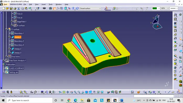
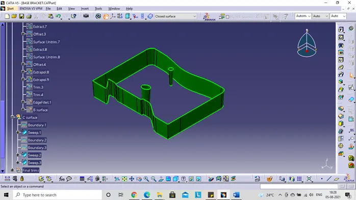
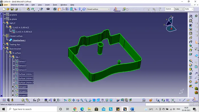
- Then join and trim them to obtain the thickened part surface
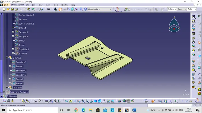
- Using part design create a solid body from the closed body feature
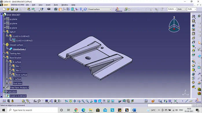
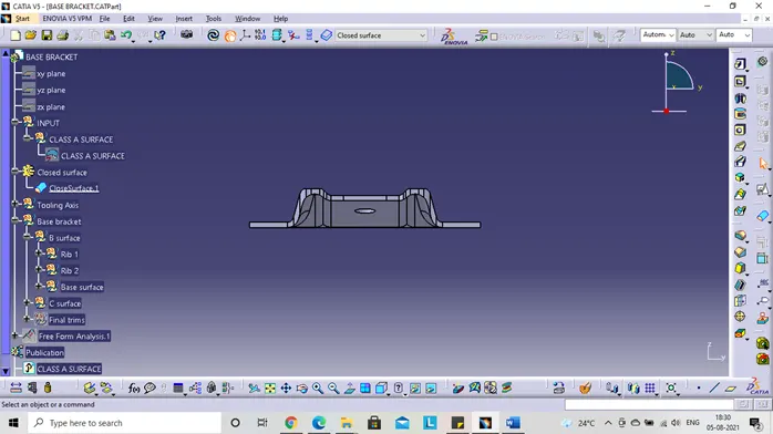
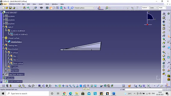
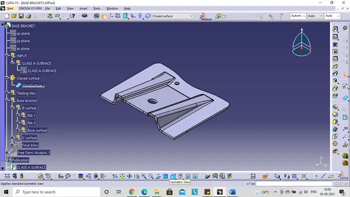
Different views of the Base bracket:
- Front view
- Left side view
- Isometric view
- Top view

Conclusion:
The draft analysis, tooling axis, B surface and C surface are created for the class A surface of the base bracket.