Week 9 - Attachment Feature Creation - Challenge 2
CREATION OF SCREW BOSE, DOGHOUSE AND DRAFT ANALYSIS FOR COIN HOLDER
Objective:
The main objective of this project is to create screw Bose, doghouse and the draft analysis for the Coin holder using Catia V5.
Introduction:
The screw Bose is used as a feature in this coin holder to fix it to the mating component by a screw. The screw Bose has its own design dimensions, and to support the screw Bose, the ribs are used at the sides of the screw Bose. The dog house is also a feature used in plastic product, in this component, this feature is used to avoid sink marks on the component and even it is used at the places, where there are perpendicular screw Bose directions and even at the more heights to the mating component.
Methodology/approach:
- For the creation of tooling axis and draft analysis, the first important input is the class A surface, then further using Catia V5, create the tooling axis and draft analysis, first, check the best direction (X, Y, Z) and select the direction at which the part will easy to remove from the mold. Y direction is selected for the Tooling axis. Create a dummy tooling axis for reference.
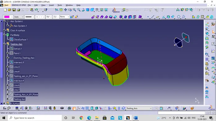
- For creating the tooling axis use the Y direction, use the bisecting method for creating the tooling axis, first draw a intersection curve in ZY plane and then use the vertical line and draw a bisecting lines for both of them to get a centre axis line so we can have the centre for the tooling axis.
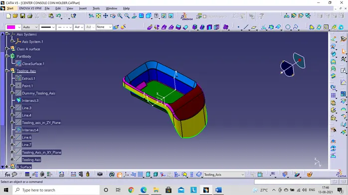
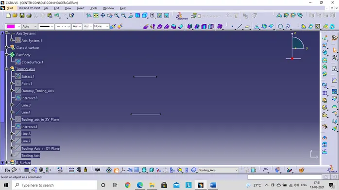
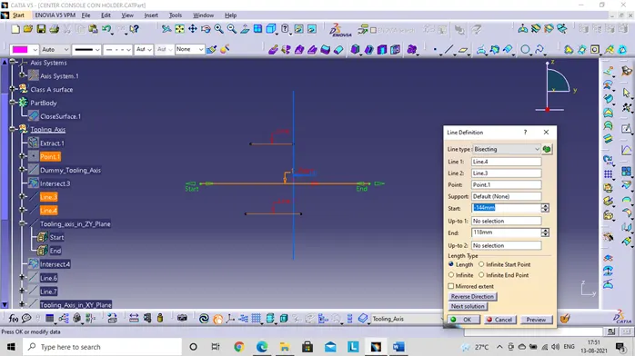
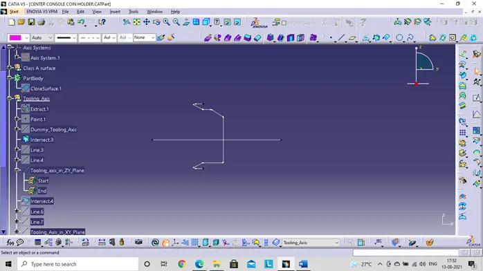
- Then perform the same in the other XY plane and get the bisecting lines for the tooling axis. Then use both the tooling axis in XY and ZY plane and get the bisecting line for them to produce the main tooling axis.
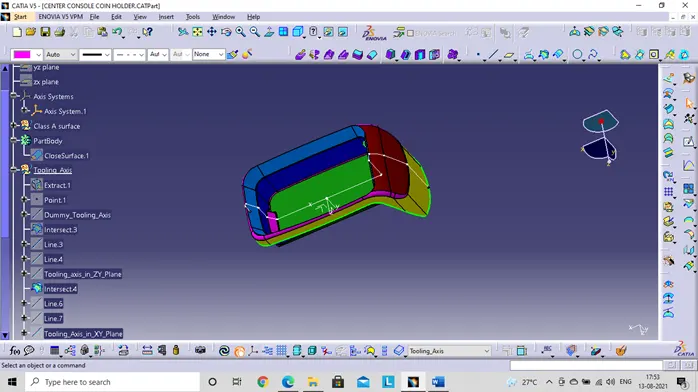
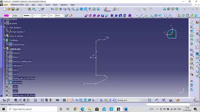
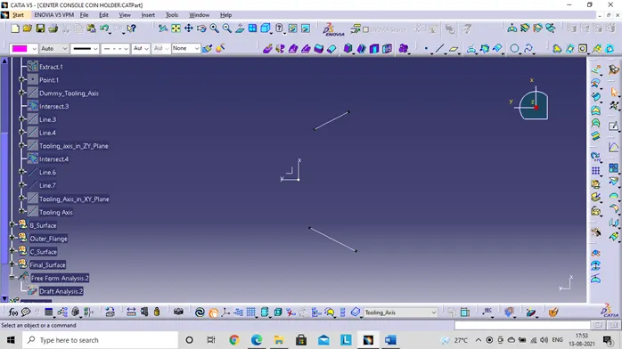
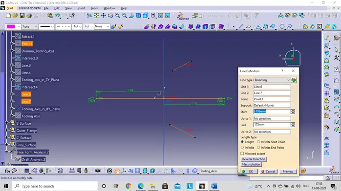
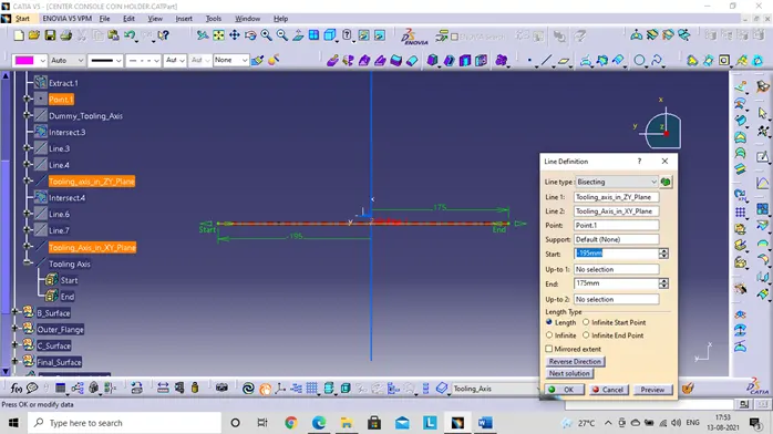
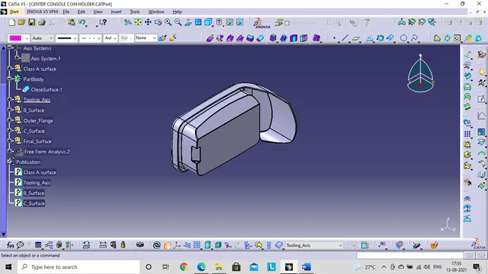
- Publishing – Use the publish option to publish the Class A surface and the tooling axis, so it is easy for using it for other features.
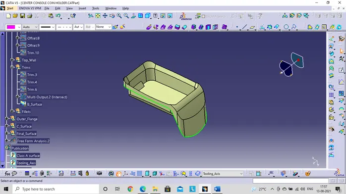
- Thicken the coin holder using some of the surface features, since the edge fillet has to be at equal distance on the offset surface, we add the thickness to the edge fillet, the final offset will be the B surface.
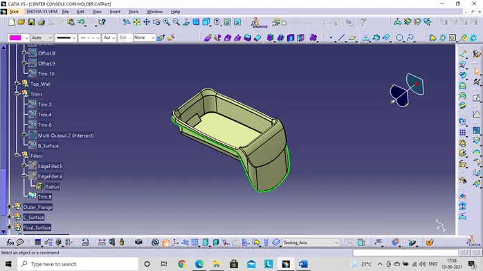
- The C surface is the surface which give the thickened body surface. This is made using the sweep surface option with the reference as outer surfaces of class A surface.
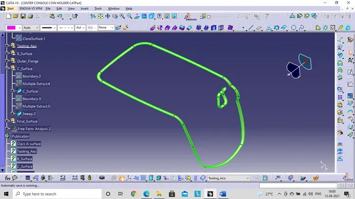
- Then join and trim them to obtain the thickened part surface.
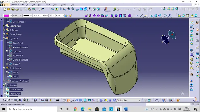
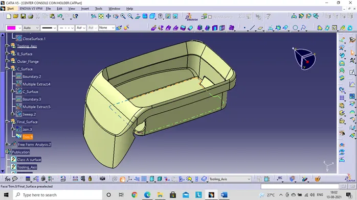
- Using part design create a solid body from the closed body feature.
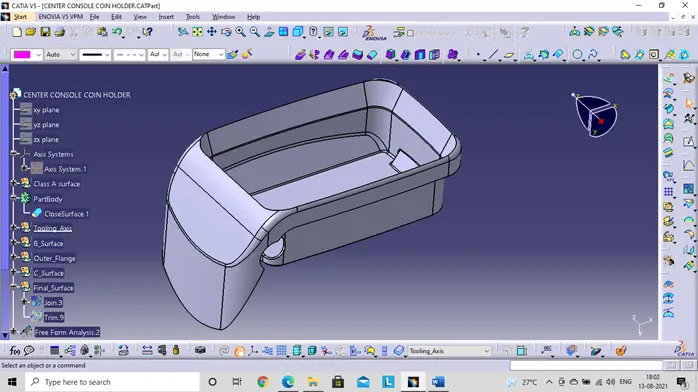
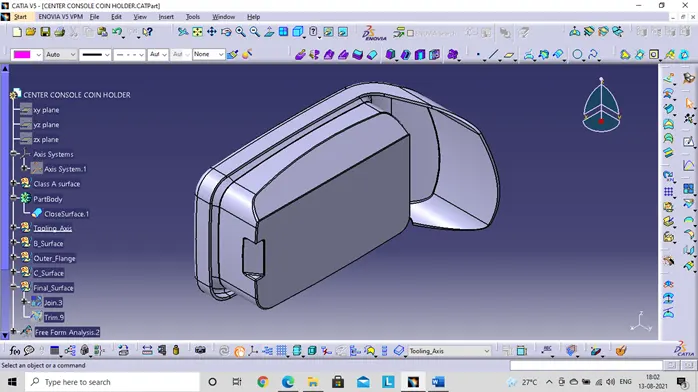
Now let’s move on to the Rib design & analysis for this component:
Some of the important design aspects are:
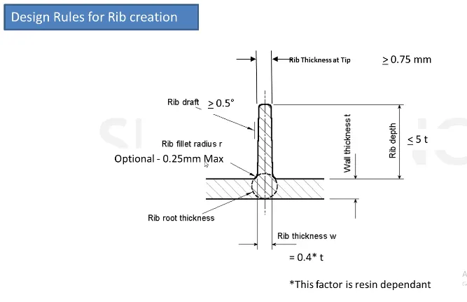
For the coin holder design the Thickness(t) is 2.5 mm
So Here are some calculations for the Coin holder ribs:
- Rib thickness at tip = should not be less than 75 mm
- Rib draft angle = Should not be less than 5 degree
- Edge fillet = Should not be less than 25 mm
- Rib depth or height = Should be greater than 5t, for this design 5*2.5=5 mm
- Rib root thickness = This should be 30% less or more than the thickness(t).
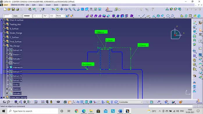
- The spacing between ribs = There are two considerations which is 3:1 and 2:1, in this design I have considered 2:1, which is Y is the depth 12.5mm and X is unknown, which is equals to 2, so Y/X=2
- X will be 5 mm
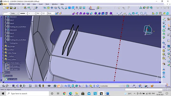
Let us now see the designed values:
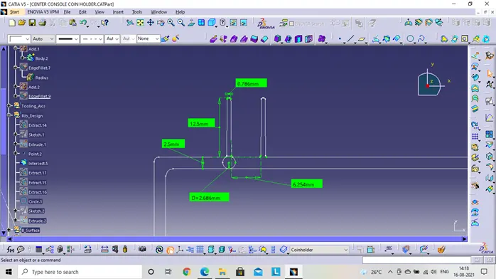
The root design is suitable for this component thickness; hence the design can be used for manufacturing.
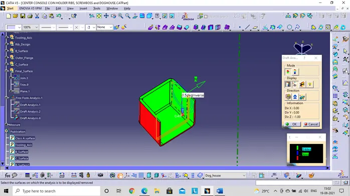
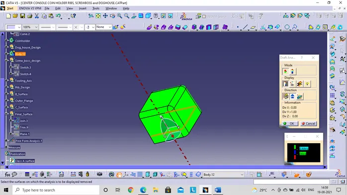
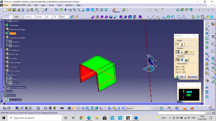
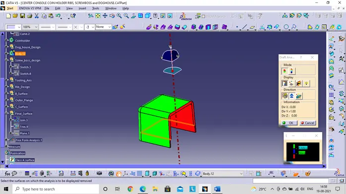
- Then, use the feature draft analysis to check the draft analysis of the coin holder using the tooling axis.
- Use the analysis>Feature draft analysis toolbar to check the draft analysis, Use the compass and place in the main tooling axis direction line being upwards and lock it.
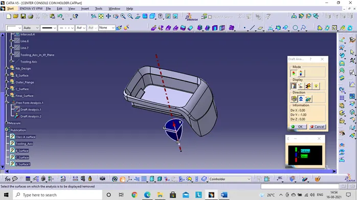
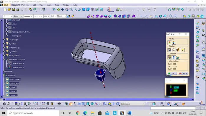
- Select the axis and the part so that the color changes according keeping the reference as tooling axis.
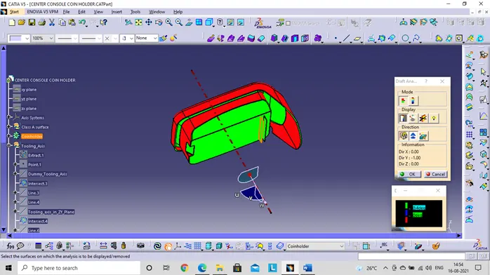
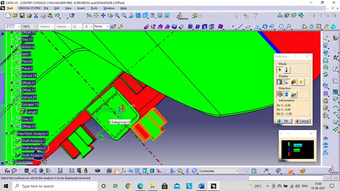
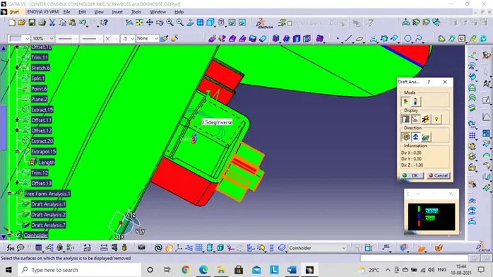
- On the quick analysis mode there are 3 colors green, red and blue. We can change the values as per our standards, in this coin holder part the class A surface has most of the sides with 0-degree draft which is very difficult to manufacture, it is recommended for the class A surface to be improved with minimum draft angle at the 0-degree walls. The ribs can be seen having a draft angle of 0.5 degree do by this the draft analysis is good for the ribs designed.
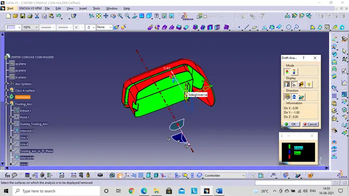
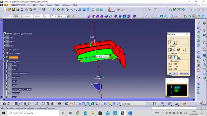
- Analysis on running point - with the help of this option, the angles at every point can be checked easily. The area with green color can be suitable for the present tooling axis.
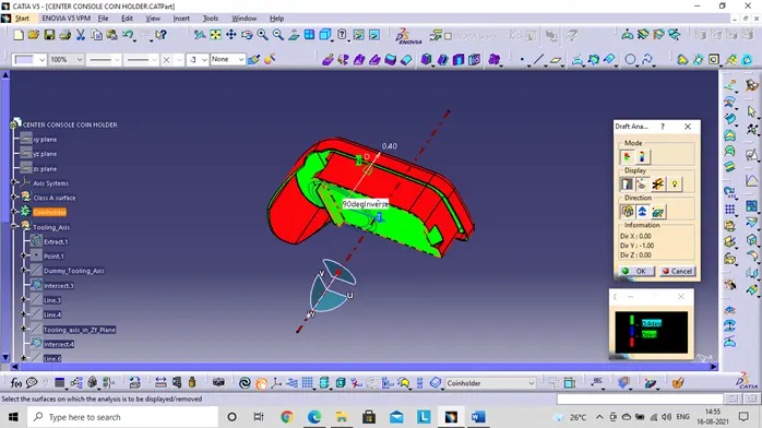
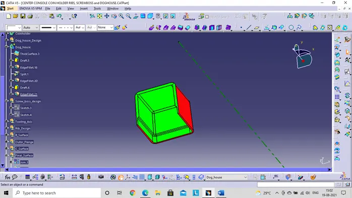
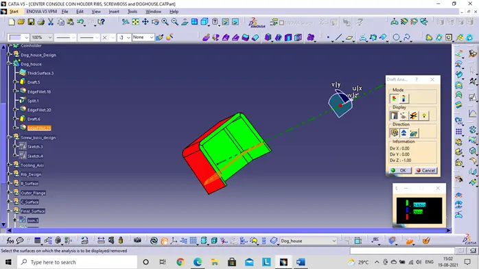
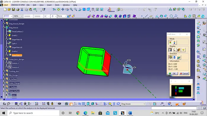
The draft analysis is obtained for the closed surface of coin holder with ribs.
Now let’s go for the design of Screw Bose and the dog house
There are some of the design dimensions for the creation of these two they are:
- Draft - 0.5 degrees on walls of bose.
- Thickness - Typically 40%* of the nominal wall at the base.
- Height to Diameter Ratio - 3:1
- Radii - 0.25mm maximum radii.
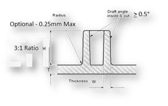
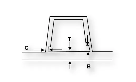
For the dog house:
- "C" is where the doghouse contacts the backside of the surface
- Doghouse wall thickness at the intersection of the part wall (C) should be 40% or less than the main wall stock (T).
- Height of (B) should be between 3.0 – 6.0 mm
So, the designed dog house and screw Bose are shown below using these dimensions
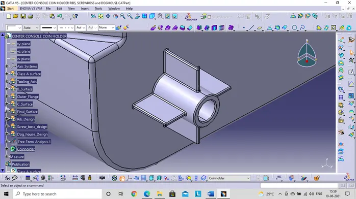
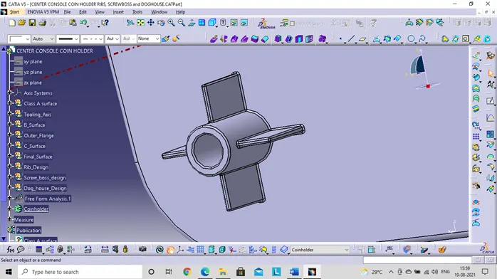
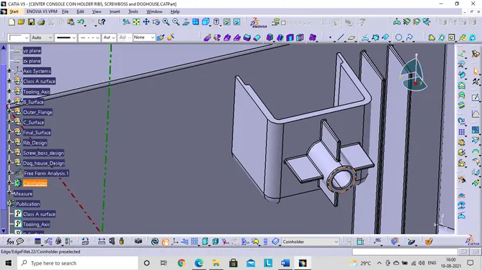
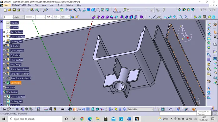
The draft analysis is performed on the screw boss and the dog house with main tooling axis and sliding tooling axis. Draft angle here is 0.5 degree.
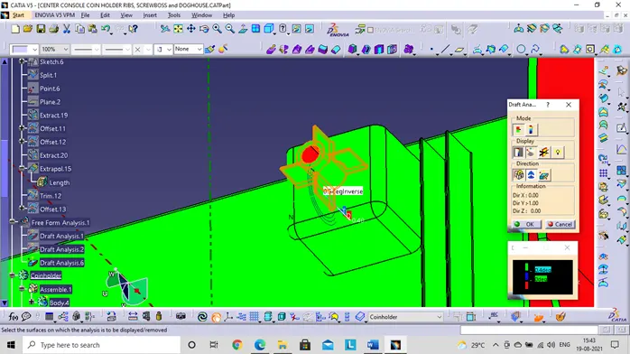
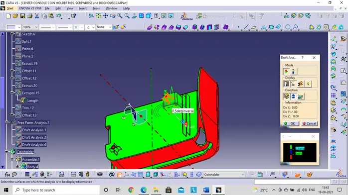
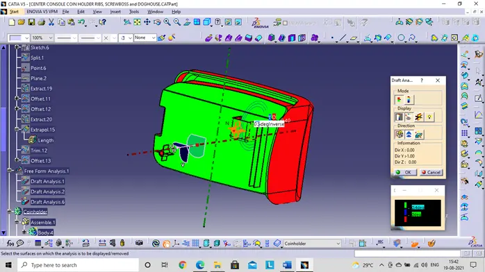
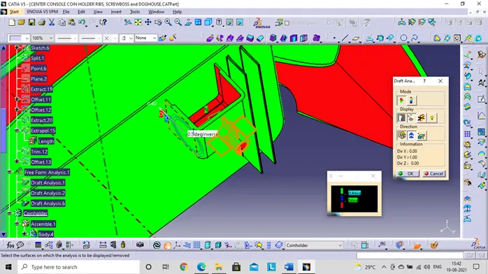
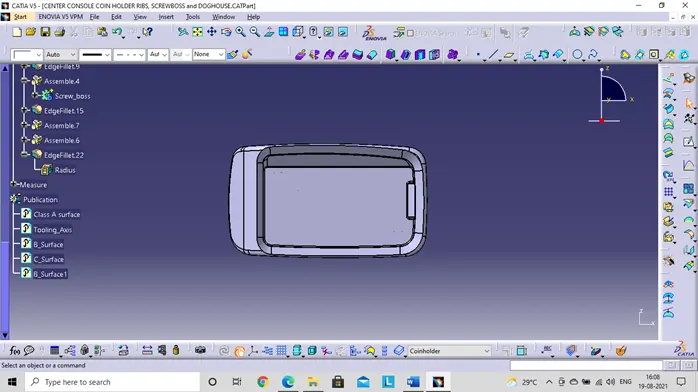
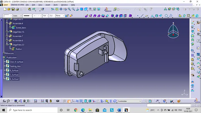
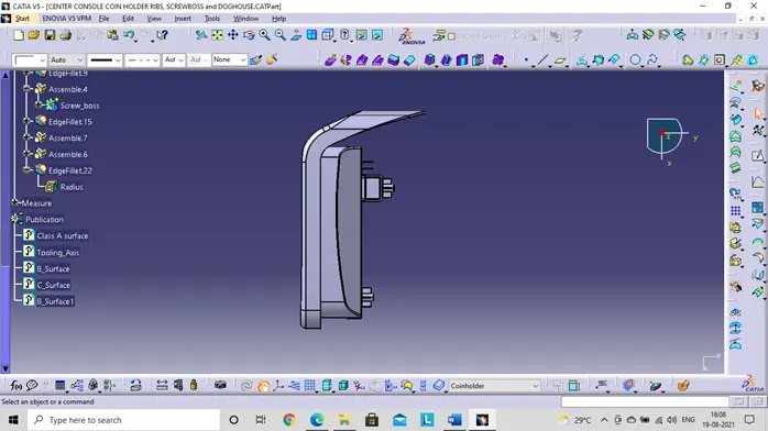
Different views of the coin holder with Ribs:
- Front view
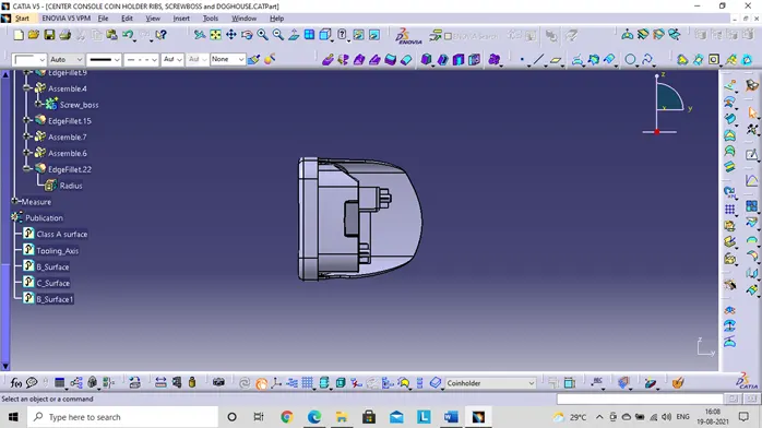
- Left side view
- Isometric view
- Top view
Conclusion:
The screw bose, dog house and draft analysis is carried out for the coin holder.