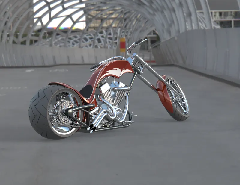
Photo Realistic Rendering
MODELLING AND VISUALIZATION OF AN AMERICAN CHOPPER USING SOLIDWORKS
Objective:
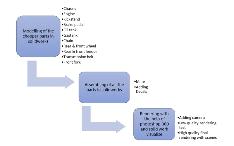
The main objective of this project is to model the required parts for the American Chopper, assemble all the parts and render the assembled chopper with the help of solidworks visualize.
Introduction:
Solidworks is a software which is used for planning, grabbing in visual ideas, modelling, feasibility, assessment, prototyping, and project management. This software is used in designing and building of mechanical, software and electrical elements. This gives us more efficiency in building any part and brief idea of how the final element will be the end product. We use solidworks software to design each part required for the American chopper, then the assembly is made simple using the same solid works software, for rendering purpose, the solidworks visualize software is used where it helps in rendering the assembled American chopper in a smooth way.
Design methodology/approach:
Description:
Chassis:
It forms the main skeleton of the chopper, all the components are mounted to the chassis
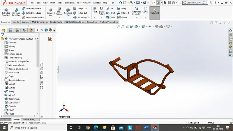
Features and tools used while designing chassis:
- Sketch
- Offset entities
- Convert entities
- Projected curve
- Create plane
- Extruded boss
- Revolved boss
- Swept boss
- Extruded cut
- Fillet
- Chamfer
- Combine
- Trim entities
- Mirror
- Composite curve
- Split tool
Sketch:
It gives us a 2D representation of the part to be built in different planes with the help of different sketch tools like lines, circle rectangle, spline, arc, straight slots and so on. Later the sketch will be taken out to build a 3D part
Offset entities:
It adds sketch entities by offsetting faces, edges, curves or sketch entities at a specified distance
Convert entities:
It converts selected model edges or sketch entities into sketch segments.
Projected curve:
It is used to project a curve in case of a complicated curve which cannot be created using single plane, it can only be created with the help of multiple planes, and finally the required curve can be projected.
Create plane:
This feature helps us to create a new plane at the required position with the help of some options and dimensions.
Extruded boss:
This feature is used to produce a 3D structure with the 2D sketch, this can be changed to required direction and dimensions also.
Revolved boss:
This feature is used to produce a revolved body to the part by the available 2D sketch, it can also be restricted to some required angles.
Swept boss:
This feature sweeps a closed profile along an open or closed path to create a solid feature.
Extruded cut:
This feature cuts the solid model by extruding a sketched profile in one or two directions.
Fillet:
This feature creates a rounded internal or external face along one or more edges in solid or surface feature.
Chamfer:
This feature is also as same as fillet but here there are options to create angle and distance as required at the edges:
Combine:
This feature is used to combine the body’s all together so the design gets smooth view and it can also be differentiated for some specified parts
Trim entities:
This feature is used to trim of the portion which is not required in the sketch.
Mirror:
This feature is used to get the same surface or body on the other side, the reference can used as a plane or line, the modelling is made easier with help of this option.
Composite curve:
This feature helps us to attach the two broken curves together so that the part is made easier to design.
Split tool:
This feature is used to split the unnecessary portion from the solid body and cut them out, so that we can get a good shape of the part.
Engine:
In simple it is the heart of the chopper, which functions to give the drive to the rear wheel of the chopper.
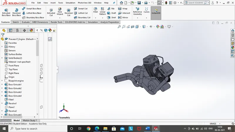
Features and tools used while designing engine:
- Sketch
- Offset entities
- Convert entities
- Projected curve
- Create plane
- Extruded boss
- Revolved boss
- Swept boss
- Extruded cut
- Fillet
- Chamfer
- Combine
- Trim entities
- Mirror
- Composite curve
- Split tool
- Linear pattern
- Circular pattern
- Dome
Linear pattern:
This feature is used to create more number of instances to the same body with some distance between them and number of instances can also be selected.
Circular pattern:
This feature is as same as linear pattern but here this is restricted to the circular path.
Dome:
This feature is used to produce a smooth round finish at the end of the part surface.
Front fork:
It consists of handle, telescopic fork, and some of the front-end accessories, its purpose is to hold different parts in the front of the motorcycle.
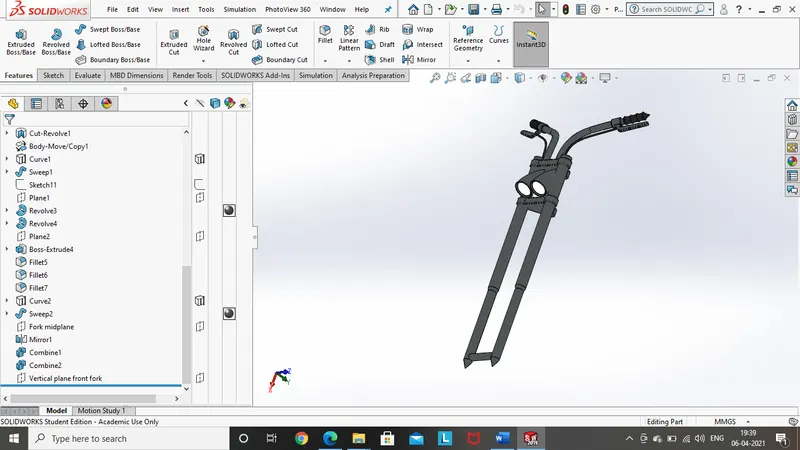
Features and tools used while designing front fork:
- Sketch
- Offset entities
- Convert entities
- Projected curve
- Create plane
- Extruded boss
- Revolved boss
- Swept boss
- Extruded cut
- Fillet
- Chamfer
- Combine
- Trim entities
- Mirror
- Composite curve
- Split tool
- Dome
Front wheel:
It consists of tire, rim, caliper and disc plate, its mounted to the front wheel.
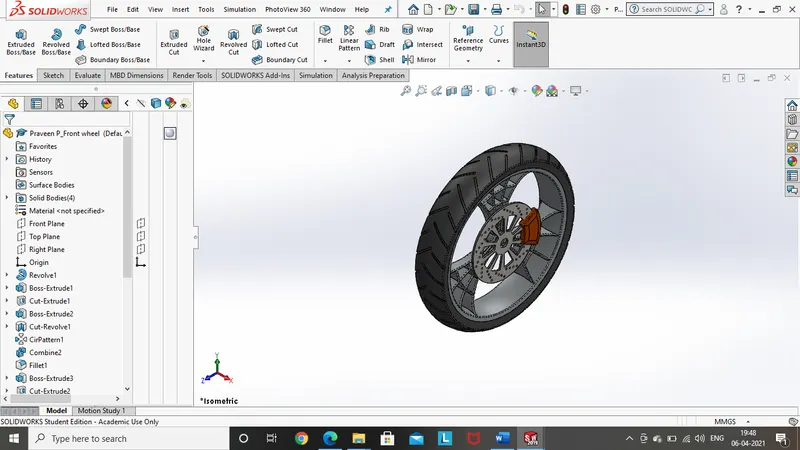
Features and tools used while designing front wheel:
- Sketch
- Offset entities
- Convert entities
- Create plane
- Extruded boss
- Revolved boss
- Extruded cut
- Fillet
- Chamfer
- Combine
- Trim entities
- Mirror
- Split tool
- Circular pattern
- Revolved cut
Revolved cut:
This feature is used to produce a revolved cut on the part with the help of sketch.
Rear wheel:
It is mounted on the rear side of the chassis, its function is to rotate on its shaft or axis, which keeps the motorcycle moving front and back, and the brakes plays its role in terms of braking.
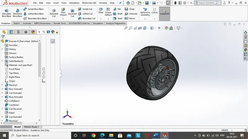
Features and tools used while designing rear wheel:
- Sketch
- Offset entities
- Convert entities
- Create plane
- Extruded boss
- Revolved boss
- Extruded cut
- Fillet
- Chamfer
- Combine
- Trim entities
- Mirror
- Split tool
- Circular pattern
- Revolved cut
Rear fender:
This rear fender is used to keep the closure for the rotating wheel, this helps in keeping the direct contact to the wheel away.
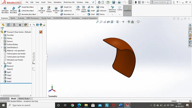
Features and tools used while designing rear fender:
- Sketch
- Offset entities
- Convert entities
- Extruded boss
- Revolved boss
- Fillet
- Trim entities
- Split tool
- Revolved cut
- Shell
Shell:
This feature removes material from a solid body to create a thin-walled feature..
Front fender:
Its function is as same as the rear fender but is on the front side of the chopper on the front wheel.
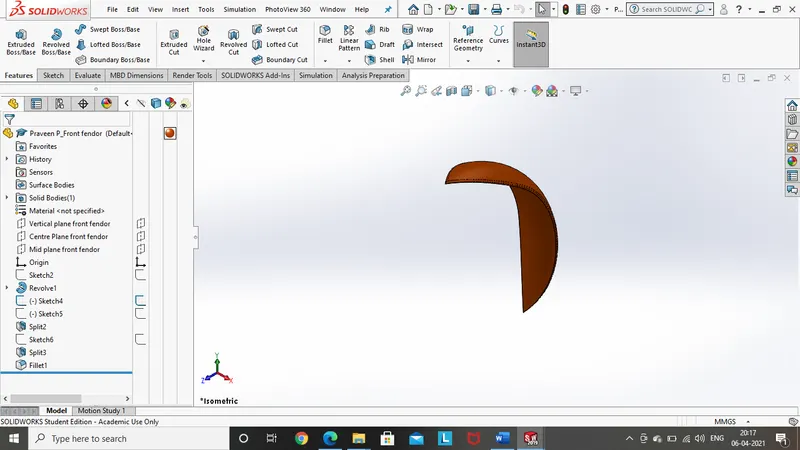
Features and tools used while designing front fender:
- Sketch
- Offset entities
- Convert entities
- Extruded boss
- Revolved boss
- Fillet
- Trim entities
- Split tool
- Revolved cut
- Shell
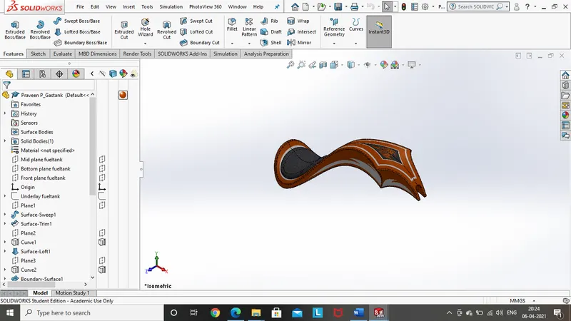
Gas tank:
It is mounted in the top of the chassis which contains gas to run the engine.
Features and tools used while designing gas tank:
- Sketch
- Offset entities
- Convert entities
- Projected curve
- Create plane
- Extruded boss
- Revolved boss
- Swept boss
- Extruded cut
- Fillet
- Chamfer
- Combine
- Trim entities
- Mirror
- Composite curve
- Split tool
- Dome
- Surface knit
- Cut sweep
- Surface loft
- Boundary surface
- Surface sweep
Surface knit:
This feature is used to combine two or more adjacent, non-intersecting surfaces together.
Cut sweep:
This feature cuts a solid model by sweeping a closed profile along an open or closed path.
Surface loft:
This feature creates a lofted surface between two or more profiles.
Boundary surface:
This feature creates a boundary surface between profiles in two directions.
Surface sweep:
This feature creates a surface feature by sweeping than open or closed profile along an open or closed path.
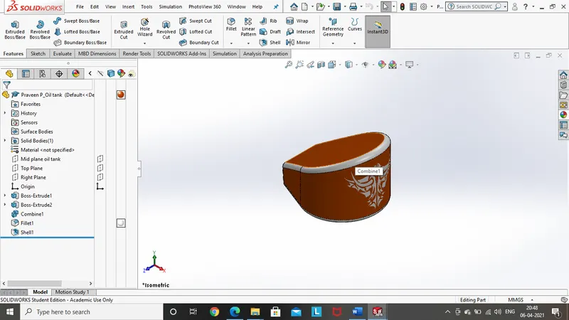
Oil tank:
This tank is used to store the oil, required to provide the lubrication for the engine parts.
Features and tools used while designing oil tank:
- Sketch
- Offset entities
- Convert entities
- Extruded boss
- Fillet
- Combine
- Trim entities
- Mirror
- Combine
- Shell
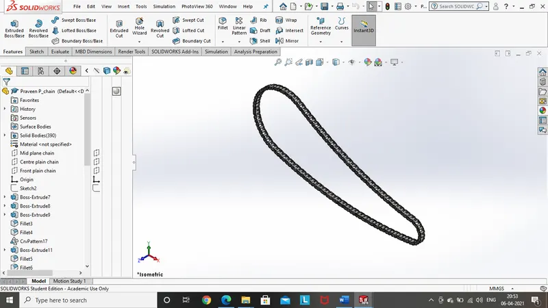
Chain:
This Component is used to transmit the drive from the transmission to the rear wheel.
Features and tools used while designing chain:
- Sketch
- Offset entities
- Convert entities
- Extruded boss
- Fillet
- Trim entities
- Mirror
- Circular pattern
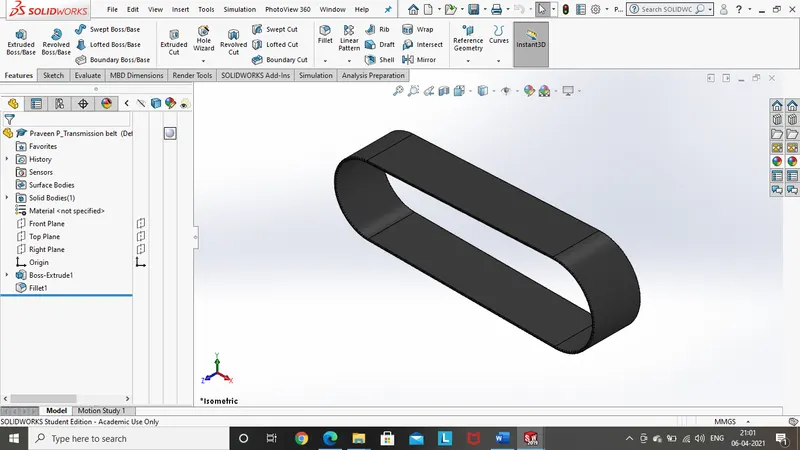
Transmission belt:
Its function is to transmit the drive from the engine to the transmission/gearbox.
Features and tools used while designing Transmission belt:
- Sketch
- Extruded boss
- Fillet
- Trim entities
Pedal:
This component is mounted to the chassis on both the sides to place the leg on it.
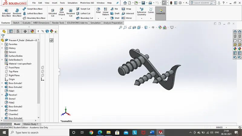
Features and tools used while designing pedal:
- Sketch
- Offset entities
- Convert entities
- Extruded boss
- Revolved boss
- Extruded cut
- Fillet
- Chamfer
- Combine
- Trim entities
- Mirror
- Split tool
- Dome
- Linear pattern
Kickstand:
This part is used to rest the motorcycle when it is in a stationary position, its design and strength is to be built such that it can withstand the whole weight of the motorcycle.
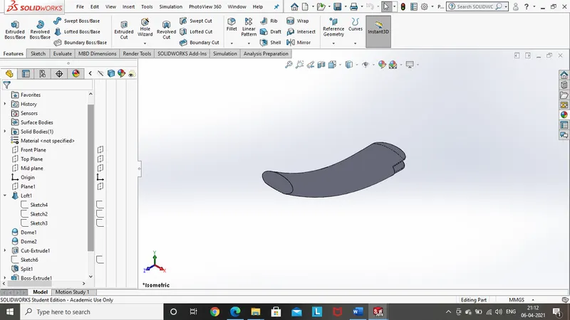
Features and tools used while designing kickstand:
- Sketch
- Extruded boss
- loft
- Fillet
- Chamfer
- Trim entities
- Split tool
- Dome
- Extruded cut
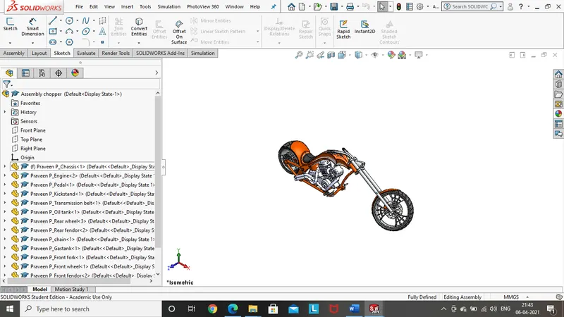
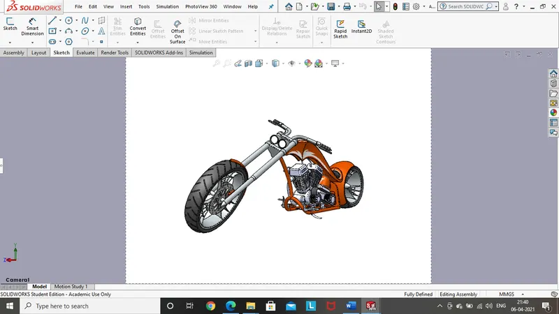
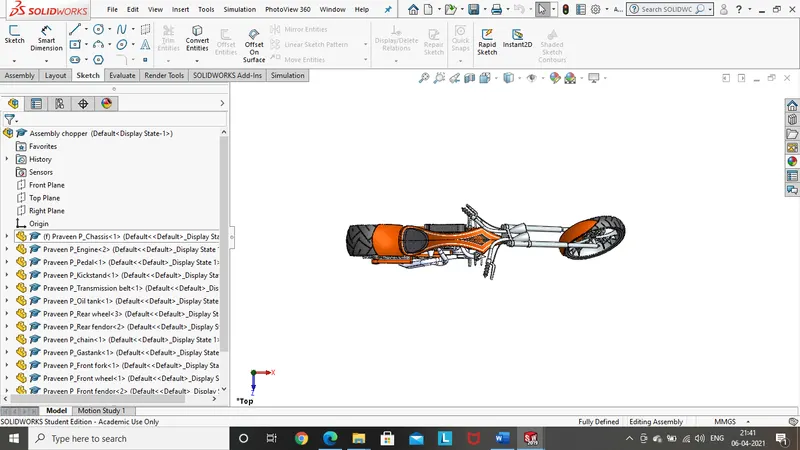
Assembly model of the chopper:
Front view:
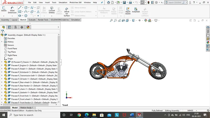
Left side view:
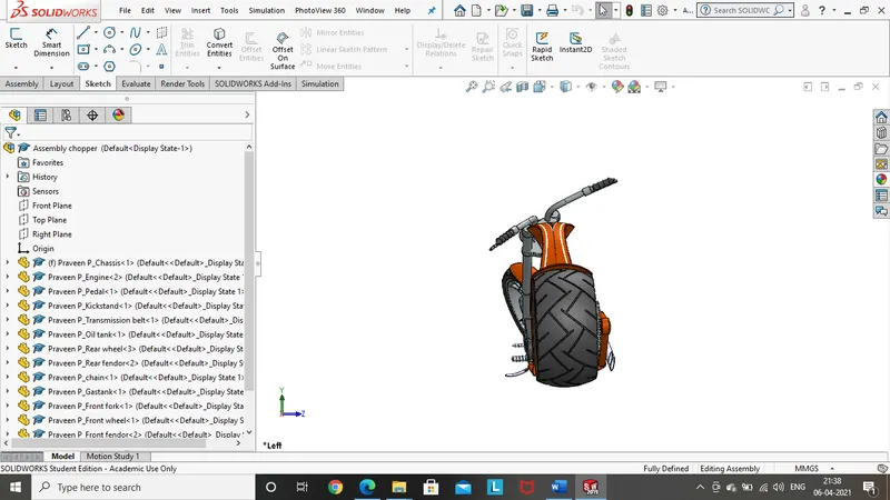
Right side view:
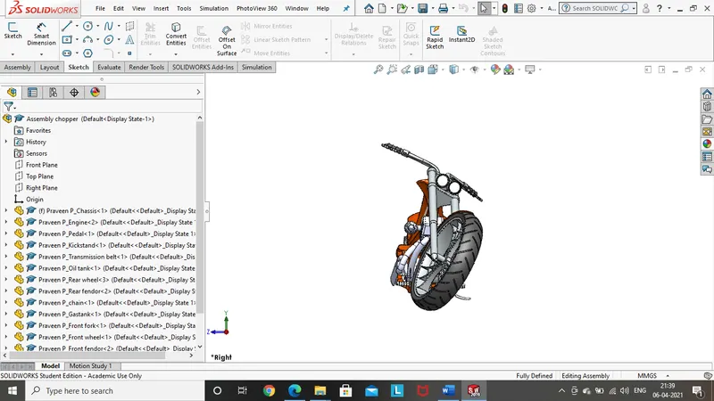
Isometric view:
Camera view:
Top plane:
Front of chopper:
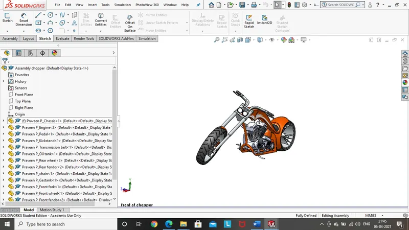
Rendering:
Solidworks rendering:
- camera setup view:
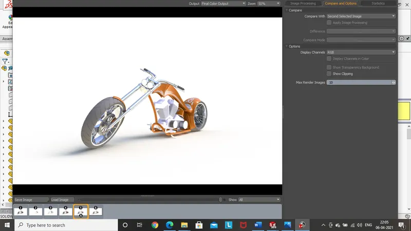
- Front view:
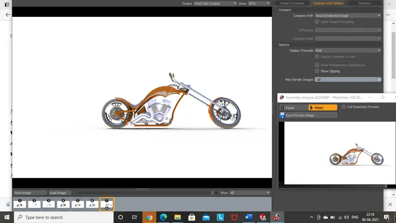
- Right side view:
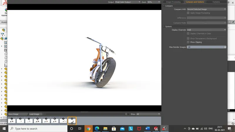
- Isometric view:
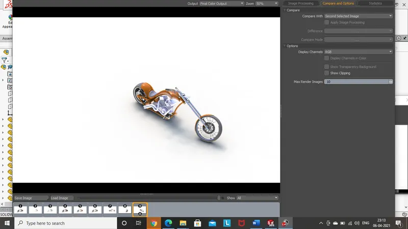
- Top view:
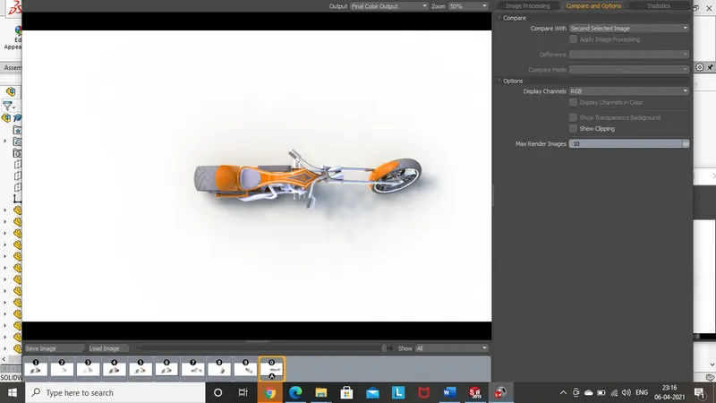
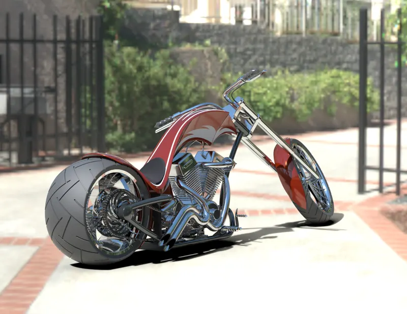
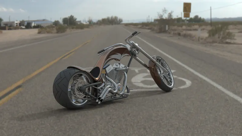
Solidworks visualize:
Conclusion:
- Each part has been built separately, to learn the complete procedure of creating a part.
- Assembly is also learnt by assembling all the parts together with some assembly tools.
- This model is built to learn the standard tools used in solidworks and solidworks visualize.
The final rendering is executed to get the final camera view and other standard views of the American chopper in various scenes.