Fender Design Challenge
DESIGN OF FRONT FENDER USING NX CAD
Objective:
The main objective of this project is to design the front fender using the engineering parameters and dimensions for the fender design.
Introduction:
Fender is the sheet metal part which is used at the front and back sides of the car, there are two fender’s at the front and two at the back, these fenders are used to cover the throwing obstacles from the wheel and safegaurd the pedestrians, and even its one surface is the style finish surface which is the outer most surface of the car side, which can be considered for good surface finishing.

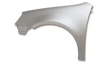
Front fender specially has some mountings to get bolted or locked to the BIW component, they are
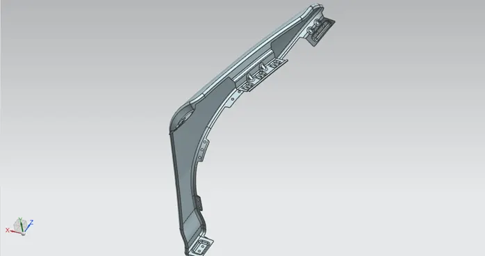
- Drip area: This is the area where the front fender is mounted to the engine compartment.
- Bumper mounting area: This is the region where the fender has a clamp to get mounted with the front bumper.
- A- pillar mounting area: This is the place where the A-pillar of the car gets mounted to the front fender.
- Sill mounting area: At this region, the fender gets a flange to mount at the bottom floor of the BIW component.
- liner mounting area: The semi-circular region below the fender is the region to mount the liner which is usually clipping type and made up of plastic materials.
Design methodology/approach:
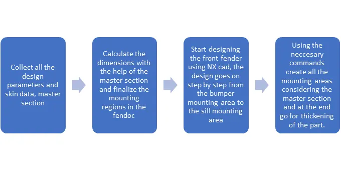
Description:
Some of the calculations and design parameters used to create each mounting in the front fender
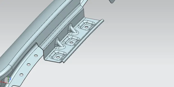
- Drip area:
For this area the master section is considered, taking this master section the drip area is designed by calculating the dimensions for modelling.
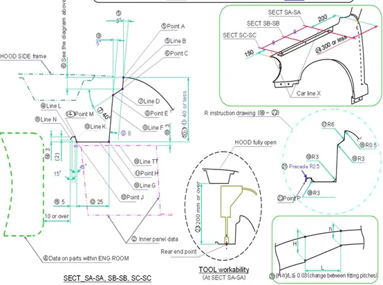
The main features used to stiffen the drip area are the dart and emboss, here dart stiffens the area by providing a bridge like structure in between so that there is no deformation of the part, emboss is used to get the flat surface on one side for the mounting and even that provides some strength to that region. The holes are created with 5 mm diameter and flat surface is maintained for 10 mm diameter from the center point of the hole for the perfect mounting.
- Bumper mounting area:
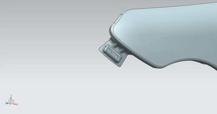
For this region the dimensions are taken into consideration with the bumper clamp design, usually it varies for different bumpers. In this design we have created two holes with 5 mm diameter, with the emboss and dart to strengthen the region and give the flat surface on one side for the mounting.
- A-Pillar mounting area:
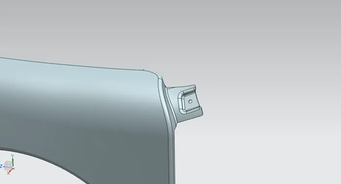
This region has an emboss and a hole of 5mm diameter which gets mounted to the A-Pillar, the design is simple here, the length varies depending on the A-pillar.
- Sill mounting area:
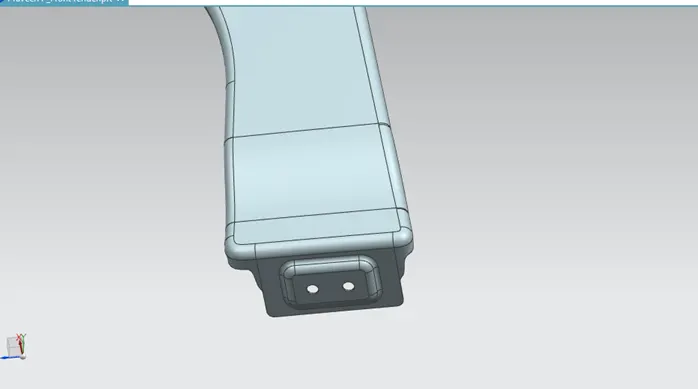
Since there is no side door mount, there are two holes provided so the mounting to the bottom floor is strong enough, again here we have an emboss with one side flat surface for the mounting.
- Front fender liner mounting area:
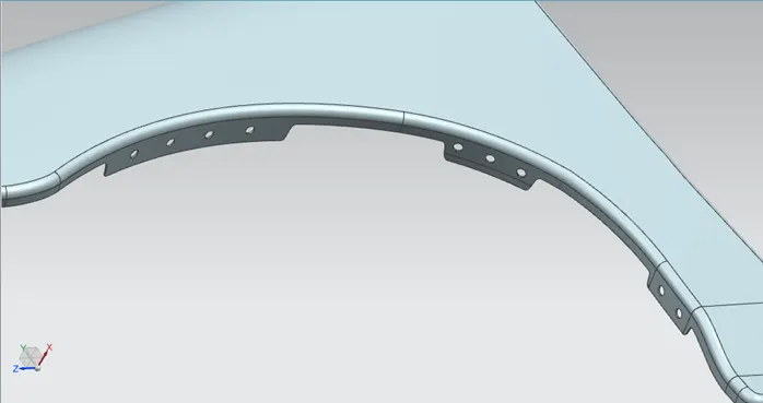
This region is clipped to the liner cover, we have provided holes for the clip mounting, more number of holes to hold the liner stiff enough, there is no emboss here since we don’t have mounting with the sheet metal component, the material which it gets mounted will be plastic.
Reliefs are provided at the sharp corners to get the smooth edges which can avoid more stress at that particular edge or corner while manufacturing the part and for the final thickening, the thickness is 0.75 mm for the part.
Views of the front fender:
Front view:
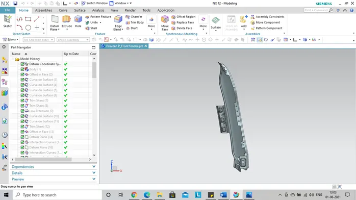
Left side view:
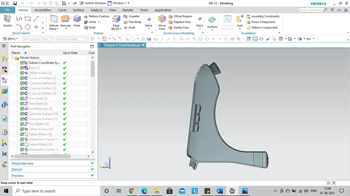
Right side view:
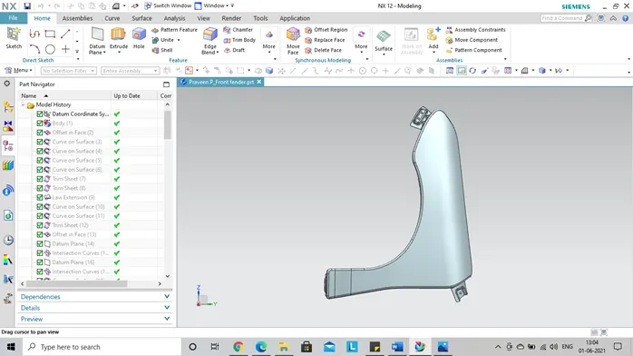
Isometric view:
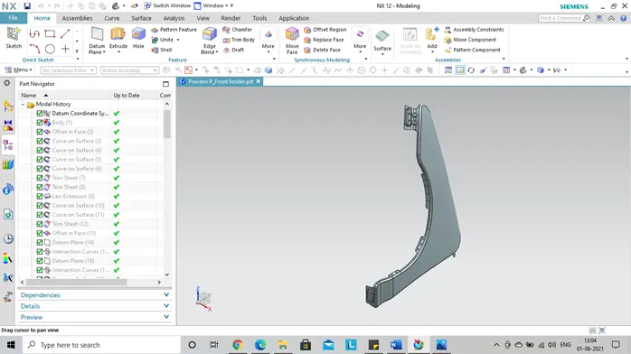
Top view:
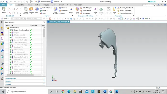
Conclusion:
The front fender is modelled using all the design parameters and considerations for all the mountings using NX CAD platform.