


Courses by Software
Courses by Semester
Courses by Domain
Tool-focused Courses
Machine learning
POPULAR COURSES
Success Stories

Week 8 - Challenge 2 - Base Bracket Design
BASE BRACKET AIM: Create the Base Bracket Plastic component through the given Class-A surface. And perform the Draft analysis on the model. METHODOLOGY: Draft Analysis: Draft analysis helps to detect if your drafted part is easily removable from the mold (in case of plastic component) or die (in case of…
Nikhil KUMAR
updated on 12 May 2021


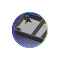
BASE BRACKET
AIM: Create the Base Bracket Plastic component through the given Class-A surface. And perform the Draft analysis on the model.
METHODOLOGY:
Draft Analysis:
Draft analysis helps to detect if your drafted part is easily removable from the mold (in case of plastic component) or die (in case of sheet metal). All plastic components will have a minimum draft of 0.5 to 3deg. And for automotive sheet metal parts, the draft will be 7deg or more. If a mold wall is perpendicular to the part ejection, there is ample friction or interference between the mold and the part which will not allow one to release from the other. This is why design engineers give a minimum draft to the part. In CATIA V5 the feature draft analysis dialog box looks like this: 
Mode:
• The mode option let you choose between quick analysis and full analysis mode.
• In quick mode there are 3 ranges with blue, red and green colours. In the case of the plastic component, we will set the draft angle as 3deg.
Display:
• The first box is to open and close the colour scale dialogue box.
• The second box is the analysis under running point, when activating the checkbox and move the pointer over the surface. This option enables you to perform local analysis. Arrows are displayed under the pointer, identifying the normal to the surface at the pointer location (green arrow), the draft direction (red arrow), and the tangent (blue arrow). As you move the pointer over the surface, the display is dynamically updated. Furthermore, circles are displayed indicating the plane tangent to the surface at this point. The displayed value indicates the angle between the draft direction and the tangent to the surface at the current point
• Click the No Highlight Representations button to set the display option of highlight effect sources as "on/off". When checked "On" the surfaces are selected but they will not be seen in the specification tree.
• Click the Light Effect button and the colors of the analyzed elements react to the light source.
Direction:
• The first check box is the locked direction icon which is used to lock the direction of the compass after selecting the specified direction.
• Click on the compass icon to specify the new pulling direction to remove the part.
• Click the Inverse button to automatically reverse the draft direction. When several elements are selected for analysis, the draft direction is inverted for each element when the button is clicked.
Tooling axis:
The tooling axis is defined as the direction in which the mould opens or core and cavity opens and closes. The selection of the correct tooling axis is important to ensure the component is taken out perfectly and also the cost of the component should be less. I will start by inserting a geometrical set and naming it as a tooling axis. For creating the tooling axis I will analyze the model and first create the dummy tooling axis. So on analyzing the model I found out that the z-axis will be perfect for creating the tooling axis. Because along the Z direction, only the whole component is visible.
First, I will create a point on the bigger hole and from that point, I will create one line along z-direction that will be my dummy tooling axis.

I will create a plane from the point which I have created in that hole. Then I will create an intersection of the surfaces along x and y-direction. Because the tool should be clear in both x and y-direction. Here in the x-direction, I won't be creating any intersection because in the x-direction for the Class A given it won't cause any problem. But in the y-direction, I will create the intersection between the yz plane of the axis system and the glass surface.

Then I will create lines for the surfaces that would cause problems during the ejection of the part from the mould. So basically I will extend those lines which are not perpendicular to the dummy tooling axis that I have created. Neglecting those parts which have fillets.

After doing this I will create one line bisecting the two lines that I have created and I will name it as my tooling axis. so my bisecting the lines I will make sure that the ejection should be perfect without any problems.
CLASS-B surface:
CLASS-B surface is created by extracting each wall and un-trimming and extrapolating the walls to obtain the shape by trimming the excess surfaces and offsetting it to a certain distance based on the thickness of the model. The offset surface will be the B-surface.

CLASS-C surface:
The surface created using sweep command by sweeping the boundaries of A-surface along the tooling axis to connect from A to B-surface is known as C-surface.

Using the B and C surfaces created a closed surface will be formed by trimming the excess surfaces the surfaces will be converted into a solid model using the Closed surface option.

After doing this i will go to part design and select the close surface feature to create the solid part from the surface I created.

Then I will perform the draft analysis again but this time on the whole part body. So for draft analysis, I will follow the same process as I did for the draft analysis of Class A surface That is first change the view parameters to material mode and then go to insert then analysis and under that select draft analysis.
Then I will drag the compass to my tooling axis making sure that the direction is correct. 
VIEWS


TREE


Leave a comment
Thanks for choosing to leave a comment. Please keep in mind that all the comments are moderated as per our comment policy, and your email will not be published for privacy reasons. Please leave a personal & meaningful conversation.
Other comments...
Be the first to add a comment
Read more Projects by Nikhil KUMAR (19)
Week 9 - Attachment Feature Creation - Challenge 1
AIM:- RIB DESIGN INPUT- COIN HOLDER MODEL Introduction: Rib: Ribs are thin, wall-like features typically designed into the geometry of a part to add internal support to walls or other features like bosses. In a similar fashion, gussets are support features that reinforce areas such as walls or bosses to the floor. Ribs…

16 Apr 2022 04:22 PM IST
Week 8 - Challenge 5 - Core & Cavity Design
CORE & CAVITY DESIGN OF SWITCH BEZEL AIM1. To create the switch bezel plastic component through the given class-A-surface and at theperforming the draft analysis on the model.2. Creat the core and cavity design of the switch bezel component OBJECTIVE• To ensure proper tree structure is followed.• …
14 Nov 2021 01:22 PM IST
Door Arm Rest Week 8 Challenge
AIM: To make a model from the provided class-A surface. INTRODUCTION: CLASS-A SURFACE: A surface made by the designer which is given as an input to the plastic modeller to work on. It is an aesthetic surface and the outermost surface. CLASS-B SURFACE: A surface after a certain thickness from the class-A surface…
13 Jun 2021 12:24 PM IST
Week 8 - Challenge 4 - Coin Holder Design
AIM: To make a model from the provided class-A surface. INTRODUCTION: CLASS-A SURFACE: A surface made by the designer which is given as an input to the plastic modeller to work on. It is an aesthetic surface and the outermost surface. CLASS-B SURFACE: A surface after a certain thickness from the class-A surface…
25 May 2021 03:14 PM IST
Related Courses

Skill-Lync offers industry relevant advanced engineering courses for engineering students by partnering with industry experts.


Our Company

4th Floor, BLOCK-B, Velachery - Tambaram Main Rd, Ram Nagar South, Madipakkam, Chennai, Tamil Nadu 600042.

Top Individual Courses
Top PG Programs
Skill-Lync Plus
Trending Blogs
© 2025 Skill-Lync Inc. All Rights Reserved.