Week 8 - Challenge 1 - Draft Analysis on a Fan Cover
Draft Analysis
The Draft Analysis command enables you to detect if the part you drafted will be easily removed.
This type of analysis is performed based on colour ranges identifying zones on the analyzed element where the deviation from the draft direction at any point, corresponds to specified values
The maximal draft analysis accuracy is 0.01 deg. According to the graphic card performance, this accuracy can be debated.
The different mapping analyses of the same surfaces cannot be displayed simultaneously, even if you have set the mapping analysis in no show. You need to visualize them one after the other.
Select a surface
Click the Feature Draft analysis
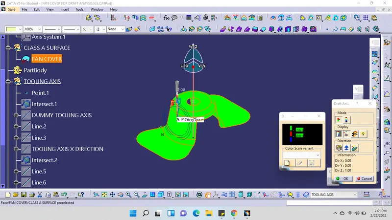
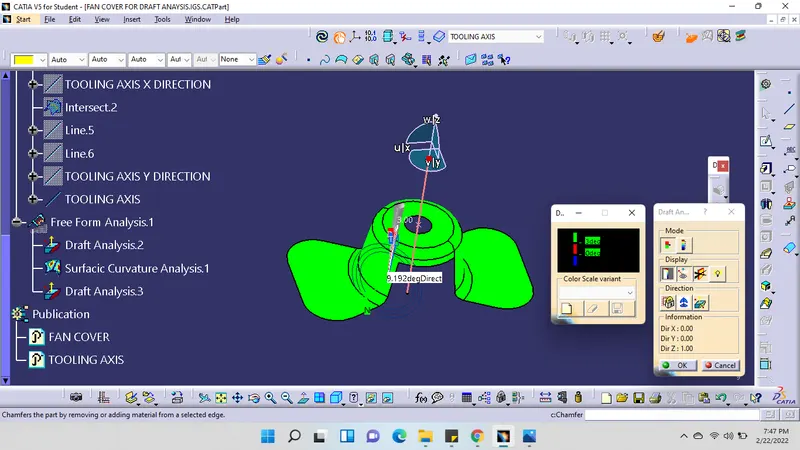
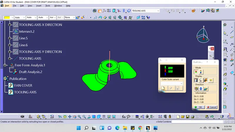
The draft analysis dialogue box is displayed. it gives information on the display colour, scale and tooling direction.
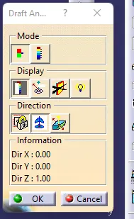
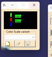
The mode option lets you choose between a quick and a full analysis mode. These two modes are completely independent. The default mode is the quick mode. It simplifies the analysis in that it displays only three colour ranges.
Quick mode
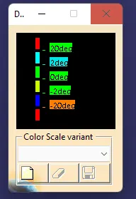
Full mode
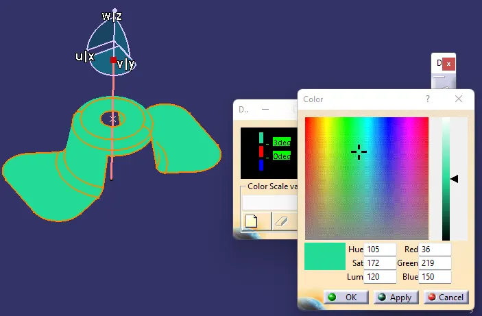
Double-click on a colour in the colour scale to display the Color dialogue box in order to modify the colour range
Double-click on the value in the colour scale to display the Value edition.
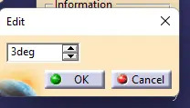
Enter a new value (negative values are allowed) to redefine the colour scale, or use the slider to position the distance value within the allowed range, and click OK.
The value is then frozen, and displayed in a green rectangle.
The colour scale settings (colours and graduated values) are saved when exiting the command, meaning the same settings will be applied when you will edit a draft analysis. New settings are created with each new draft analysis.
When the draft angle value of the surface is equal or smaller than a graduated value, the colour below the graduated value is applied.
when the draft angle value of the surface is greater than the greatest graduated value, the colour above this graduated value is applied.
Exit the dialogue box.
Uncheck the colour scale checkbox to hide the Draft analysis 1 dialogue box, this dialogue box only appears in edition mode.

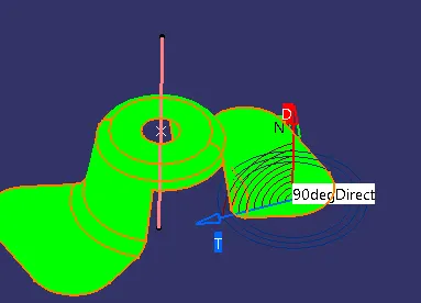
Activate the fly checkbox and move the pointer over the surface. This option enables you to perform local analysis.
Arrows are displayed under the pointer, identifying the normal to the surface at the pointer location (green arrow), the draft direction (red arrow), and the tangent (blue arrow). As you move the pointer over the surface, the display is dynamically updated. Furthermore, circles are displayed indicating the plane tangent to the surface at this point.
Click the No Highlight Representations button to set the display option of highlight effect sources as "on/off". When checked "On" the surfaces are selected but they will not be seen in the specification tree.

Click the light effects button and the colours of the analyzed elements react to the light source

Click the Inverse button to automatically reverse the draft direction

When several elements are selected for analysis, the draft direction is inverted for each element when the button is clicked
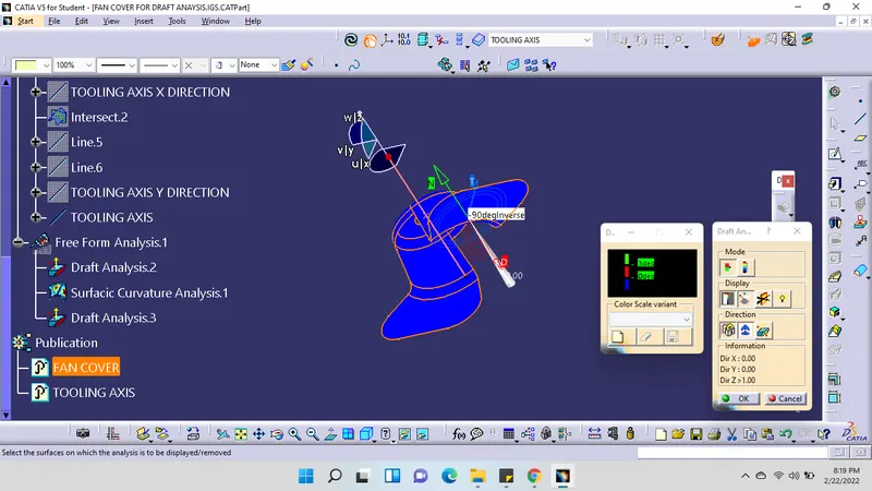
Click the locked direction icon, select a direction (a line, a plane or planar face which normal is used), or use the compass manipulators.

Click the compass icon to define the new current draft direction.