Week 9 - Attachment Feature Creation - Challenge 2
Screw Boss and Dog House
Objective:-
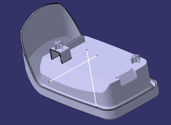
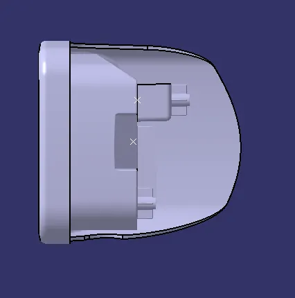
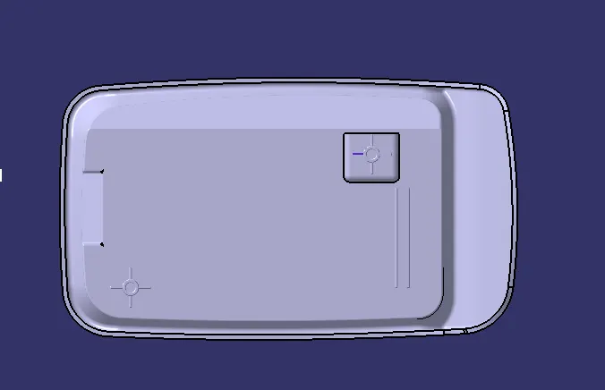
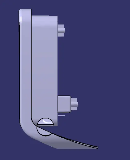
To create Center Console Coin Holder and Screw Boss and Dog house and add thickness to it and generate the Draft Analysis on a solid surface final component.
Introduction:-
Boss features are commonly found in injection moulding designs. They are used to aid in the assembly of moulded parts by providing a channel for a screw. Designing plastic screw bosses is fairly straightforward but there are a few considerations to ensure a strong connection between parts and mitigate cosmetic defects.
The dog house is an engineering feature used in the plastic trim design. Dog houses are used as a supporting feature. Sometimes other engineering features like snaps; locators etc. are mounded on them to increase their strength
PROCEDURE:
CREATING SCREW BOSS:
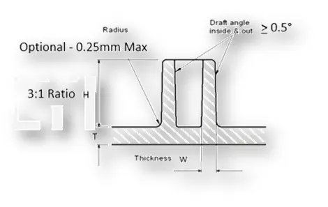
To create the Screw Boss, draw a sketch on the extracted base surface with a diameter of 5mm. For the screw boss, the thickness should be 0.6 times the thickness of the main component, so it will be 8mm.
Make it Pad by the height/diameter ratio of 3:1 ratio.
Draft the outer and inner walls of the pad at 0.5 degrees.
To stiffen the screw boss add the ribs on 4 sides by drawing the sketch on the extracted base surface and Pad it to a height not more than the rib height. Draft the walls of the ribs at 0.5 degrees.
Now add the screw boss and ribs to the main component and Unitrim the ribs which are inside the screw boss.
Fillet the edges of walls with the radii of 0.25mm. Do the Draft Analysis for the screw boss.
CREATING DOG HOUSE:
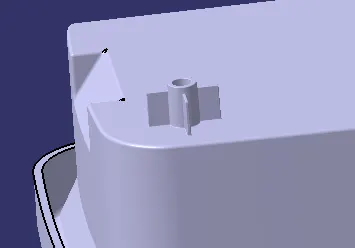
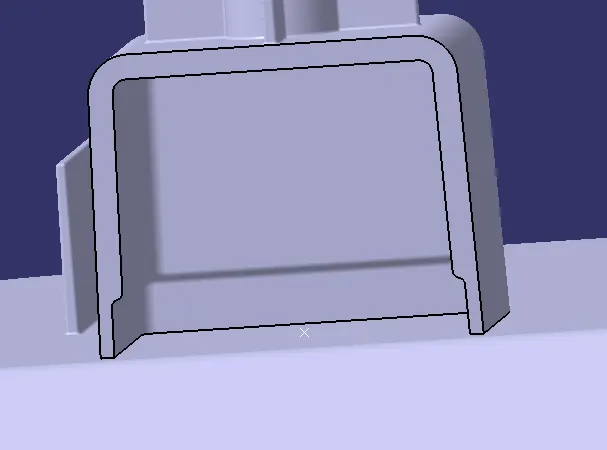
Create a sketch on the extracted base surface where the dimensions should be more than the screw boss 29. As for the Dog house, one of the sides should be opened, making one side a construction line.
Extrude the sketch by using the Sweep option with 1.5 degrees to the height of 20mm towards the top and 1mm towards the bottom.
To cover the top surface, offset the extracted base surface to a distance of 20mm and then trim it and fillet the edges with Imm. Pad the extruded surface to the outside with a thickness of 2mm. Create the tooling axis for Side Core(Yellow).
Cut the uneven surface at the open side by extracting the opposite surface and offset it to a distance toward the open surface and split the part in Part design by using the Split option.
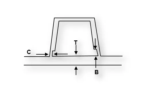
Draft the inner walls at 0.5 degrees. Now create the backside contact surface by offsetting the extracted base surface to a distance between 3-6mm height (B) and Sweep the surface to a distance of 40% of the main wall thickness (c). Trim the surface. Split the offset Surface with the body to get the cut on the backside of Dog House. Draft the Split area with 0.5degrees and fillet the surface with the radii of Imm and then translate the Screw Boss to the top of the Dog House and Add it to the Dog House and Add then component to the Main component. Do the Draft Analysis on the final component in both tooling axis.
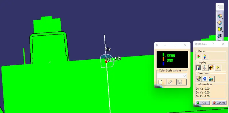
Draft Analysis
The Draft Analysis command enables you to detect if the part you drafted will be easily removed.
This type of analysis is performed based on colour ranges identifying zones on the analyzed element where the deviation from the draft direction at any point, corresponds to specified values
The maximal draft analysis accuracy is 0.01 deg. According to the graphic card performance, this accuracy can be debated.
The different mapping analyses of the same surfaces cannot be displayed simultaneously, even if you have set the mapping analysis in no show. You need to visualize them one after the other.