Advanced Sheet Metal Design Using NX Cad Challenge_2_Box Assembly
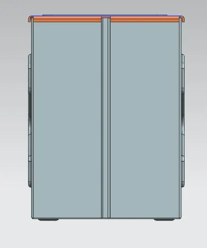
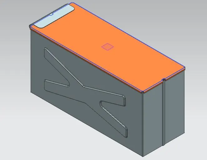
Title of the Project:- Box Assembly Using Advanced sheet metal design in the NX Cad
Objective:- To Design a box assembly using NX Cad Application.
Introduction:-
1.Sheet metal is formed by an industrial process into thin. it is a design application that using manufacturing design in NX Cad application.
2.NX Cad is function bending, cutting, tap, dimple, unbend, rebend, and Unigraphics software purely sheet metal worker used. which is owned by Siemens PLM Software.
Design Methodology:-
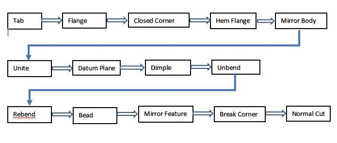
Description:-
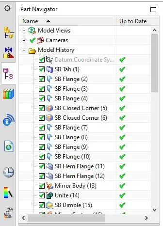
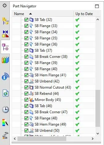
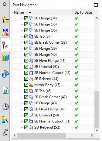
1. Tab:- Tab is creating metal sheets of specific dimensions and selection of planes. 200x150 with a thickness of 1mm.
2.Flange:- Flange create to 90 degrees with bend area radius of 10mm.
3.Closed Corner:- CLosed corner is covering the open bending area just select bend corner two or three then it will fill a gap or overlap the open area.
4.Hem Flange:- Hem is the bend area that changes as per your requirements like an open loop, close loop and etc.
5.Mirror Body:- Mirror body is copied to the same part in your selected plane without any change.
6.Unite:- Unite is united two different body selected target and tool.
7.Datum Plane:- Datum plane is a reference plane that takes as per your drawing requirement.
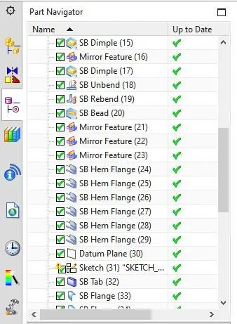
8.Dimple:- Dimple need a sketch as an input reference and you can enter depth value as per your drawing requirement.
9.Unbend:- Unbend is a open bened area.
10.Rebend:- Rebend is a close unbend area.
11.Bead:- Bead is the curve or line that specified bend selected area.
12.Mirror Feature:- Mirror Feature is a specified selected part mirror selected plane.
13.Break Corner:- Break corner is a remove Sharpe edges on corner parts.
14.Normal Cut:- Normal cut is a cut section of the targeted body or selected sketch.
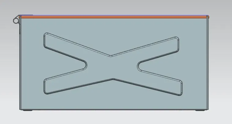
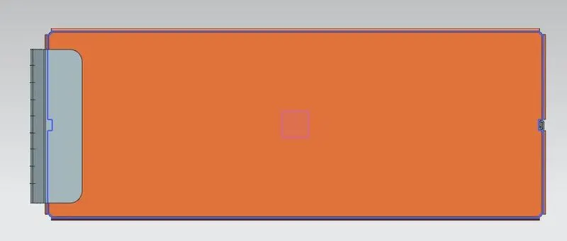
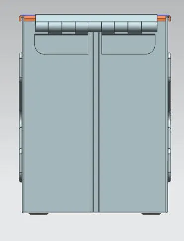
Conclusion:-
Created a Box Assembly using NX cad sheet metal application.
Changed the appearance of the model in NX environment.