Advanced Sheet Metal Design Using NX Cad Challenge_1_Casing Design
Casing Design
Objective:- The design of casing design with the help of basic commands and there used for modelling of the NX cad.
Introduction:- This report on the casing design model with the help of Siemens NXcad software is also, especially for sheet metal design. NX Cad sheet metal is an easy and effective software for sheet metal design. The casing design model is used in basic commands of the software. Where should Applying commands and what is the dimensions you need to know and nx cad help proper functioning and pop-ups?
Design methodology:-
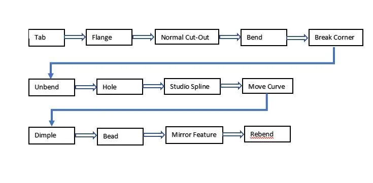
Description:-
1 Tab:- This command used on a basic sketch of the square and rectangular already added thickness value and you can also change it.
2 Flange:- This command is used in the corner edge of flange it angular, bended to the selected edge of the sheet metal.
3 Normal cut-out:- This command of using normal cut-out in the sheet metal in the shape of any sketch.
4 Bend:- This command is available in the bend group. it helps to used bend the tab along the selected curve.
5 Break corner:- This command is used to remove sharp edges of sheet metal.
6 Unbend:- This command is used to unbend the tab or sheet metal. to make another feature.
7 Hole:- This command is available under the more button of the feature group it is used to make a hole in the tab or sheet metal.
8 Studio spline:- This command is using studio spline we can form a spline by Specifying the 16 poles including the central point.
9 Move curve:- This command is using for curve formed can be rotated by using move curve option the origin is selected as the centre.
10 Dimple:- This command is using for punch. to make a dimple one of the selected sketch curve or lines and also depth input.
11 Bead:- This command is available in the punch group. its make a bread one of the selected sketch as the bead shape and depth.
12 Mirror Feature:- This command is copied selected feature and sketch. once selected plane where the mirror selected feature.
13 Rebend:- This command is used after completing features of the model then rebend and finally completed the model.
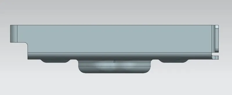
Front View
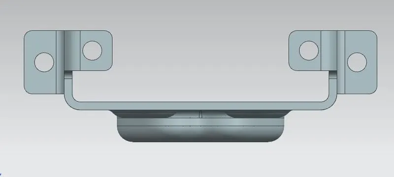
Left View
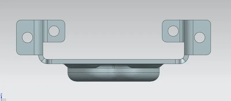
Right View

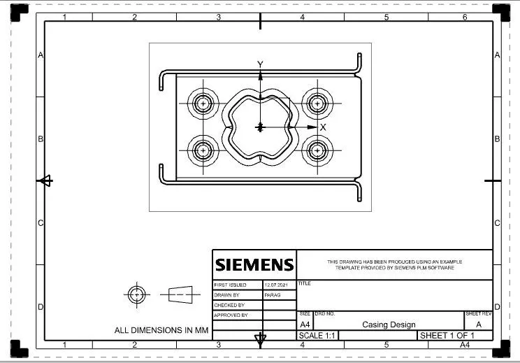
Top View
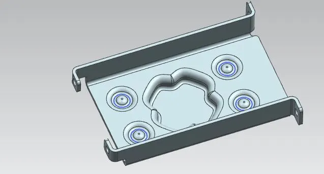
Isometric View
Conclusion:- Hence by using the above feature and following the above process we can make the required sheet metal.