Photo Realistic Rendering
Objective: To design individual parts and assembly of American chopper using Solidworks and also perform appropriate rendering using Solidworks visualize.
Introduction: An American chopper start designing from individual parts using Solidworks. solid works are easy to learn and use the software. start modelling from basic and easy parts to learn Solidworks and design one by one part and their features. In this chopper parts design, all feature and options cover in their software. after the completion of parts, the design chopper assembly will be done. The assembly of chopper mates will connect the individual parts and appearance and give them a nice look.
Design Methodology:
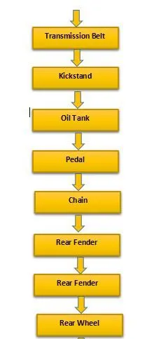
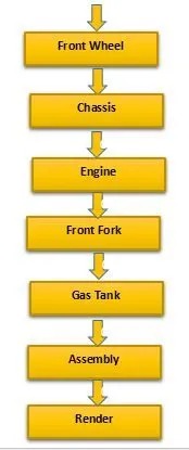
1. Transmission Belt:Description:
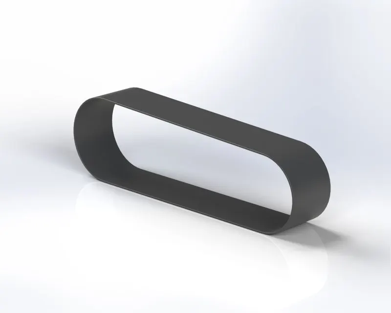
The Transmission Belt starts from sketch, offset, and gives proper dimension than Extruded Boss feature. Matte rubber appearance is given.
2. Kickstand:
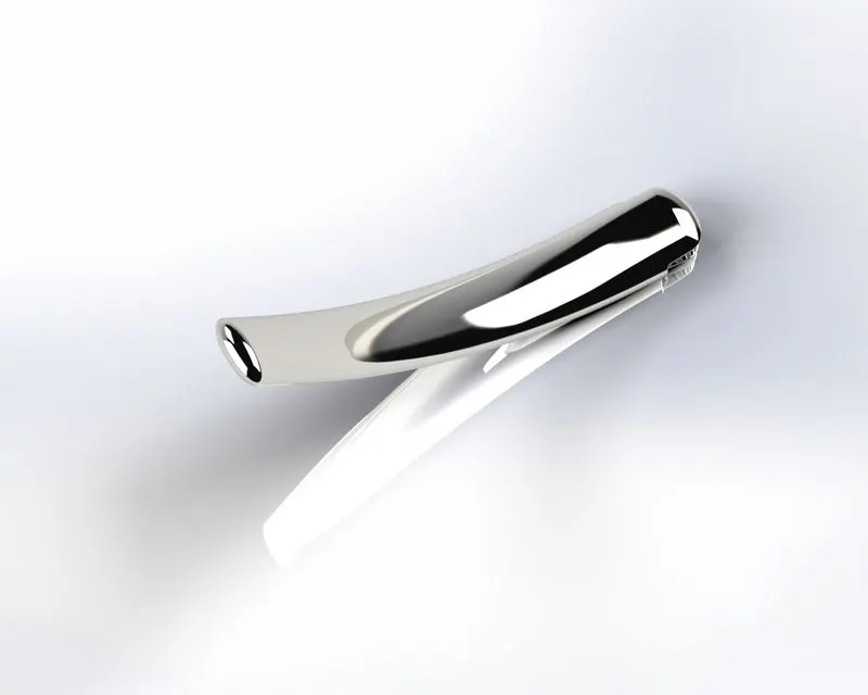
The Kickstand is also known as a side stand. The kickstand is using Loft Boss by using Ellipse sketch and some additional feature like Extrude Cut, Extrude Boss, Dome, Fillet and Split.
3. Oil Tank:
The Oil Tank is 1st hollow part construct with the help of the shell feature it is very to use this feature. it also used in combine feature because of 2 different Extrudes.
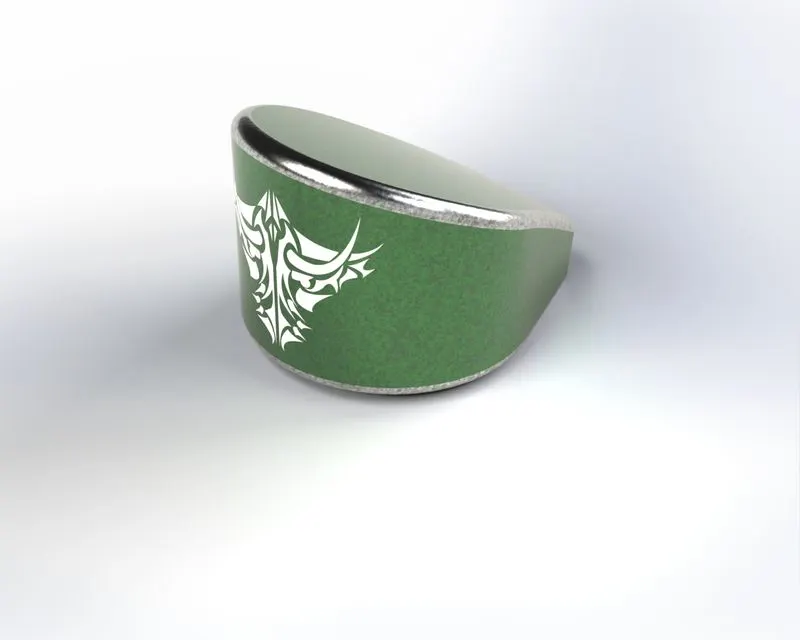
4. Pedal:
The Pedal is modelled using Extrude Boss and Revolved Boss feature. also added some additional feature like Dome, Chamfer, Fillet and Linear Pattern.
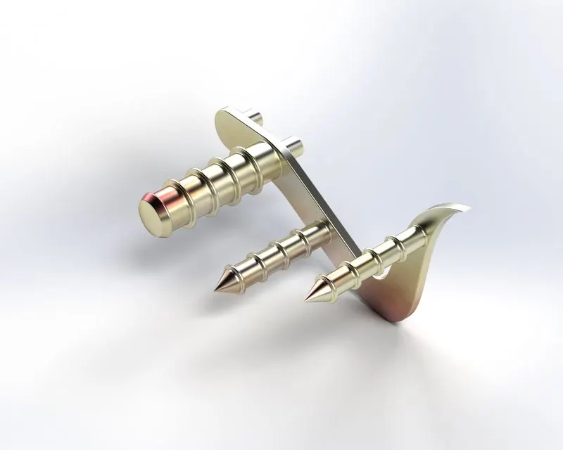
5. Chain:
The Chain is the main part of the drive mechanism which use to transfer power from gearbox to wheel. A chain designed is a little tricky making a Block link and Extruded this than using Curve driven Pattern.
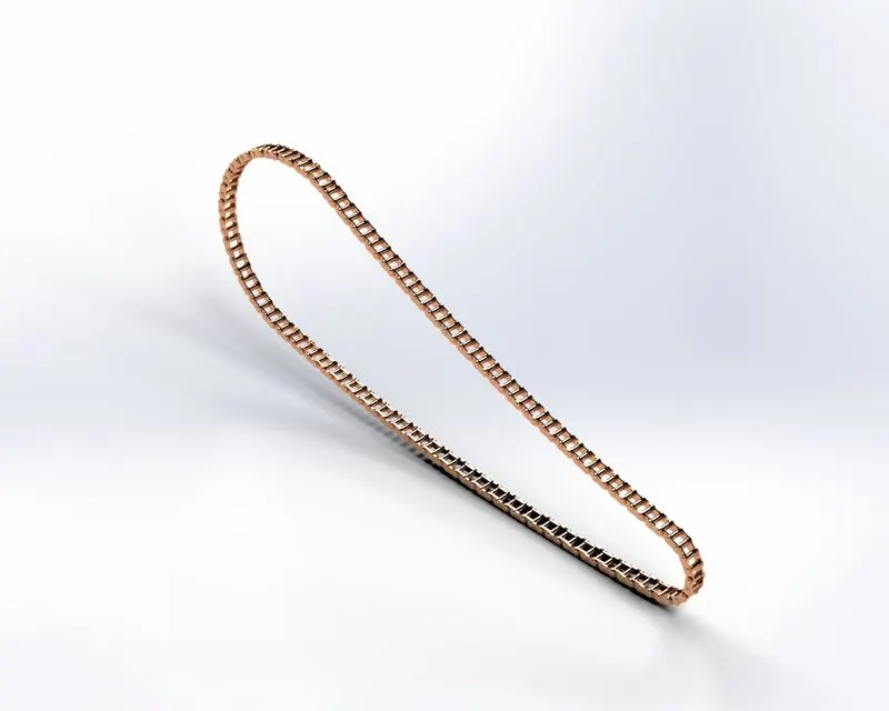
6. Rear Fender:
Rear Fender is the cover of the rear wheel for a designer that uses Revoled Boss, Shell, Fillet and Decal.
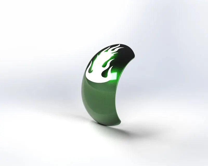
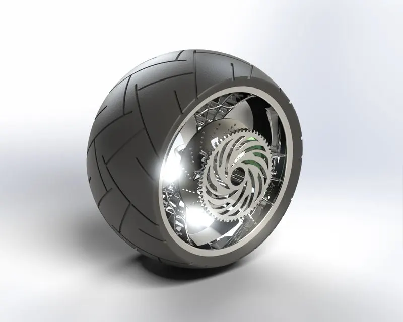
7.Rear Wheel:
Rear Wheel combine some different parts like Tyer, Rotor, Sprocket, and Calliper. Several features used in rear wheel design Revolved Boss, Extruded Boss, Extruded Cut, Revolved Cut, Linear Pattern and Circular Pattern etc.
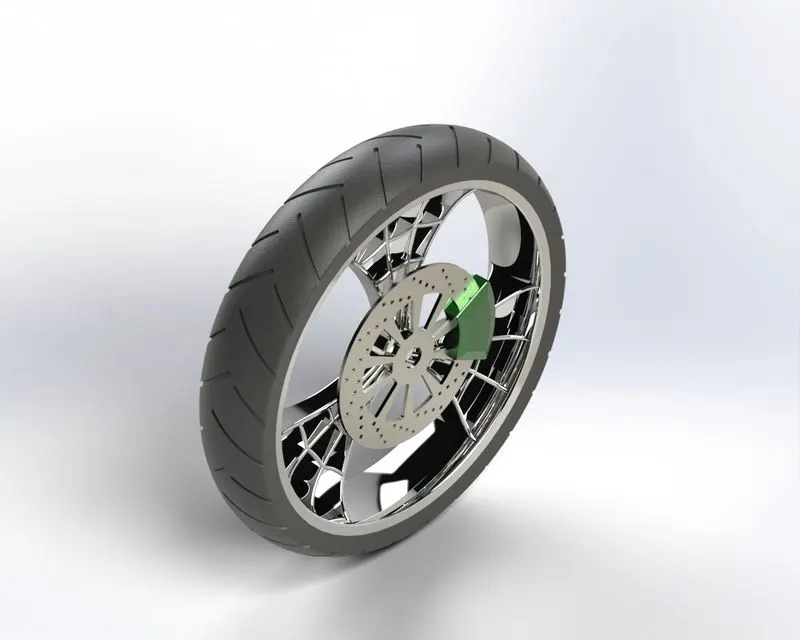
8. Front Wheel:
Front Wheel connected to Rotor and calliper. Several feature use of Revolved Boss, Extruded Boss, Extruded Cut, Revolved Cut, Linear Pattern and Circular Pattern etc.
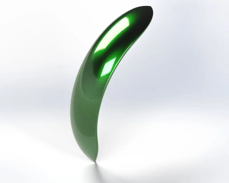
9.Front Fender:
Front Fender is a cover of the front wheel that was modelled simply by Revolved Boss, Shell, Fillet etc.
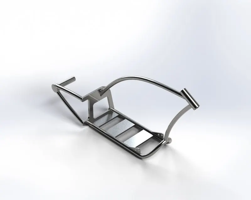
10. Chassis:
Chassis is a Maine core part of Chopper for design use reference image known as a blueprint. The feature used for chassis Extruded Boss, Revolved Boss, Swept Boss, Extruded Cut, Combine, Fillet, Chamfer and Dome.
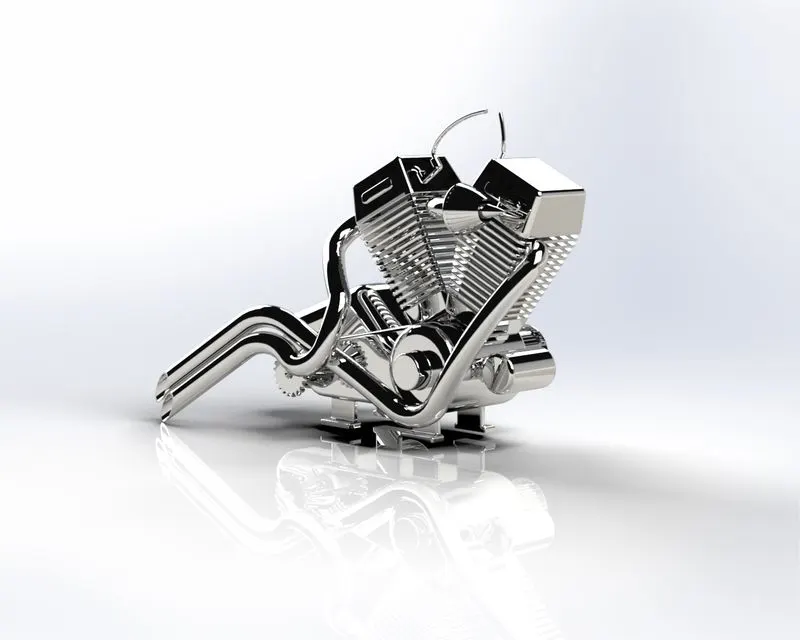
11. Engine:
An Engine is also known as a motor. This is a V engine specially chopper type bikes using V engines. The reference image was taken to design the engine as a blueprint. To create an Engine using some feature Extrude Boss, Revolved Boss, Extrude Cut, Linear Pattern, Circular Pattern, Combine and Project Curves. Also use some basic feature to remove sharp edges Fillet, Chamfer, and Dome.
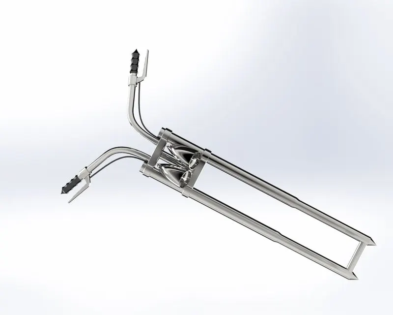
12. Front Fork:
The Front Fork is a connecting link between the Front Wheel and chassis. The feature used in Move Body, Project Curve and repeated features Extruded Boss. Revolved Boss, Combine, Swept Boss and Mirror.
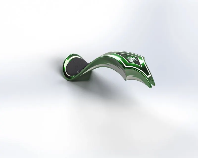
13. Gas Tank:
In Gas Tank used Surface Modelling Feature these surface were then stitched with the help of knit surface command. a feature used in gas tank Boundary Surface, Lofted Surface, Trim Surface, Swept Surface etc.
Assembly:
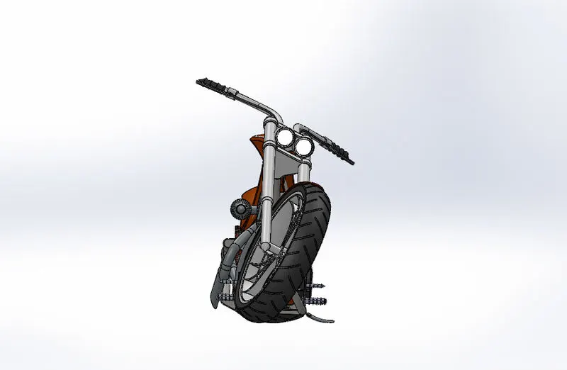
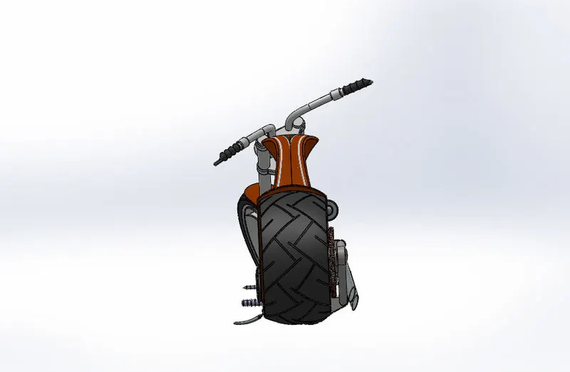
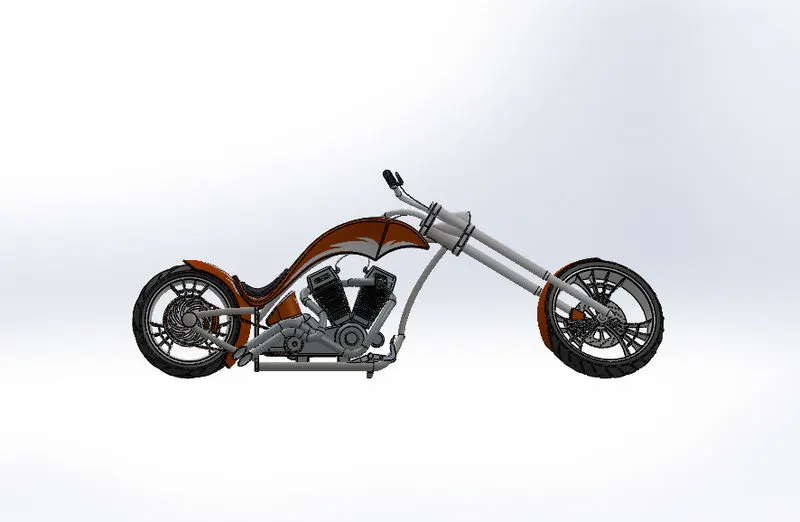
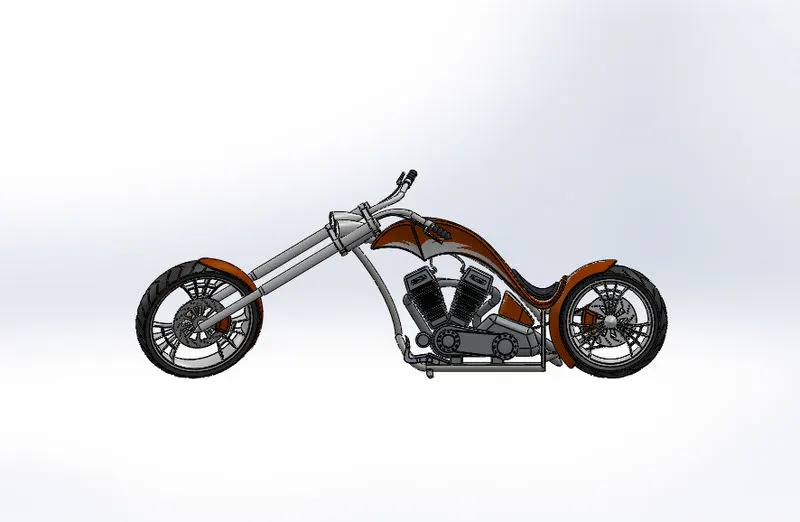
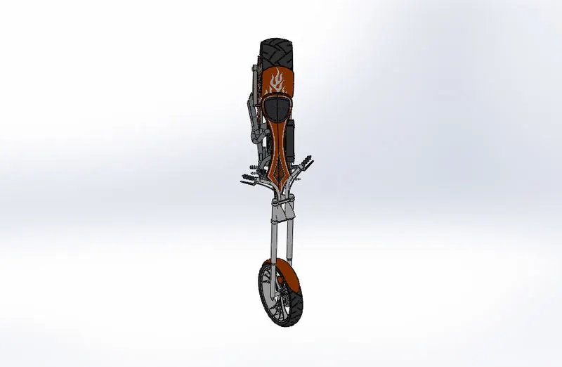
Assembly starts from the chassis is the only part that connected all other parts. Using standard mates such as Coincident, Concentric, Parallel, Tangent Etc. Also some additional mates like an Angel for Transmission Belt and KickStand. One dimension used for the Engine.
Front View:
Back View:
Left View:
Right View:
Top View:
Isometric View:
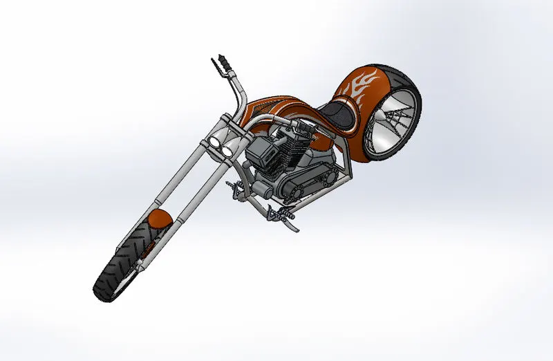
Camera View:
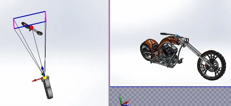
Rendering:
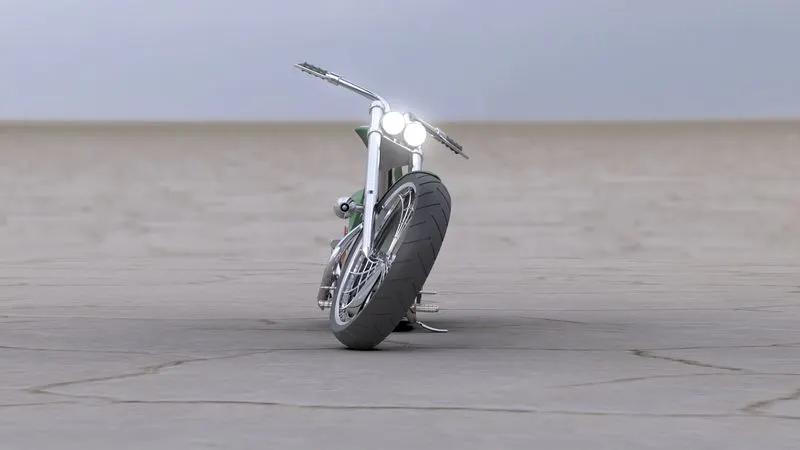
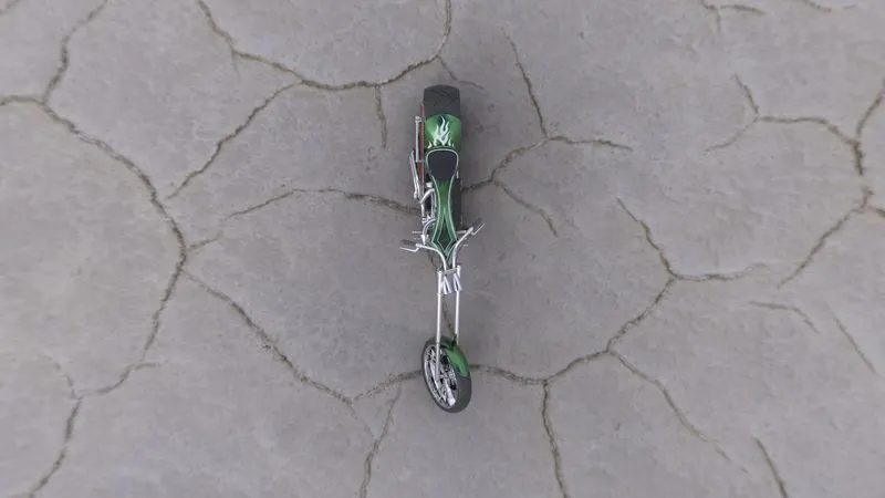
The Chopper Assembly is rendered using Solidworks Visualize Tool provided by Solidworks. Rendering is the process of creating realistic images of the photorealistic model with the environment. appropriate Environment is set for this purpose and also suitable colour, light, camera as per the environment and model. the perspective view is enabled to ensure real-time look. after proving a suitable appearance the model is rendering.
Front View:
Top View:
Side View:
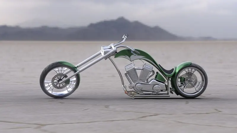
Isometric View:
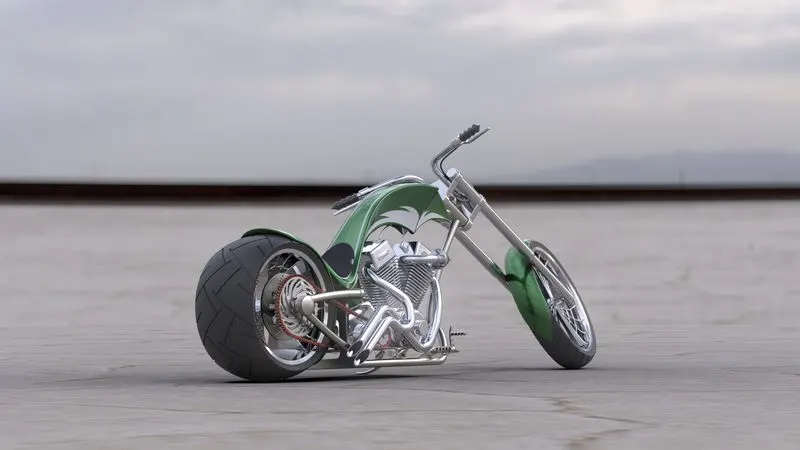
Camera Setup View:
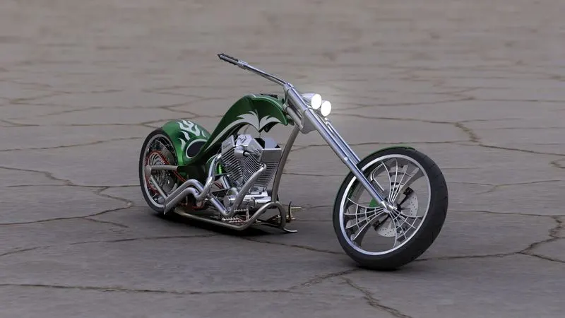
Conclusion:
Hence, The American Chopper body part is modelled on Parts File, Assembly File in Solidworks. Assembly for rendering on Solidworks Visualize tool.