Week-7 Head Impact
AIM :
To perform Head Impact simulation on the car hood and calculate the HIC (Head Injury Criteria) value. In this study, a simple head impact on the rigid wall is studied at first. Then the impact of given Headform model with a rigid wall is studied further followed by Headform impact on the hood model.
Deliverables :
- The impact simulation of a simple head impact with the Rigid wall.
- The impact simulation of the Headform provided with the Rigid wall with the Stress / Strain plots and acceleration plot.
- The impact simulation of the head form with the Hood with the Stress / Strain plots and acceleration plot. For the hood, you can use Aluminium.
- The Stress / Strain plot from the Rigidwall simulation should be compared with the Stress / Strain plot from the Hood Simulation.
INTRODUCTION :
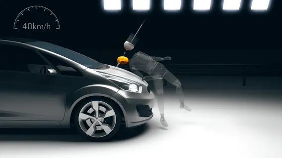
Car-pedestrian accidents account for a considerable number of automobile accidents in industrialized countries. Head injury continues to be more concerned in Automobile impacts. Because the head is the most seriously injured part in many collisions including in pedestrian automobile collisions. Head injuries are the most common cause of pedestrian deaths in car to pedestrian collisions. To reduce the severity of such injuries international safety committee have proposed subsystem tests in which headform impactors are impacted upon the car hood. Pedestrian protection has become an increasingly important consideration in vehicle crash safety. Pedestrianvehicle crashes cause a significant number of pedestrian fatalities and injuries globally. Computer models are powerful tools for understanding how to reduce the severity of injuries in such crashes. Headform impactors are used to test the behaviour of vehicle structures such as the hood.
Pedestrian Head Impact
In a pedestrian-vehicle impact, the kinematics and severity of pedestrian injuries are affected by the impact locations on the vehicle and body velocities after impact. The Head injuries cause a serious threat to life and recovery is often incomplete. Therefore, it is most important to evaluate injury risks to the head. The objective of this project is to analyze the pedestrian kinematics in a Pedestrian-Car accident scenario and determine the Head Injury Criteria (HIC) from the head resultant acceleration, for head impacts at various locations on the vehicle hood. This analysis shows the effects of variations in pedestrian height on head impact position and on the potential head injury risk to the pedestrian.
Severity Index (SI) and the Head Injury Criterion (HIC)
The first model used in practice was the Severity Index SI. The value of the deceleration was weighted by a power n, the value of which depended on the part of the body according to empirical experience. For the head, n = 2.5 was chosen. The SI was defined in mathematical form by
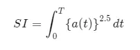
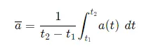
with n = 2.5 for the head, and with T equal to the complete duration of the deceleration having an effect on the head. The validation of the model was not satisfactory for comparison of different car types and different accident situations. Adaptation of the empirical data led to the currently used HIC value as a revised model. First, we look at the mean acceleration between two times t1 and t2 as shown in the figure below.
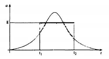
Acceleration vs. Time plot
The factor (t2 - t1)* a^(2.5) takes into account both duration and weighted value of the deceleration for the time interval t1 to t2. The maximum of all such numerical values is the Head Injury Criterion which is given below.

Apart from the condition 0 < t1 < t2 < T, the starting point t1 and the time period `Delta`t = t2- t1 are arbitrary at first. To be able to evaluate the measured curve practically, one makes some simplifying model assumptions:
- We demand t2 — t1 < 36 ms. Longer deceleration times do not increase the injury risk, according to experience.
- Peak acceleration values must last 3 ms. This requirement has reasons of measurement technique and is supported by the assumption that decelerations of shorter duration do not have any effect on the brain.
TOOLS REQUIRED :
- LS-PrePost
- LS-Run
PROCEDURE :
The whole study on Head impact is carried out in three cases, starting from the simple model setup in the first case and introducing complexities (models and simulation environment) in the further cases.
NOTE : (kg.mm,ms) unit system is followed consistently throughout the whole study.
Case I - Simple Head model impact on a Rigid Wall
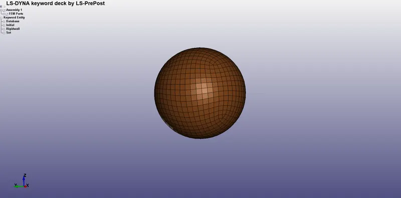
- A simple abstract Head geometry is given with the problem statement. This geometry is meshed with shell elements.
- To replicate the impact with a rigid wall, a rigid wall is created from Create Entity -> Rigidwall -> Geom -> Flat utility. The created rigid wall is normal to the Z-axis and placed some distance away from the simple head geometry. The rigid wall is generated by picking one node and the normal to the rigid wall.
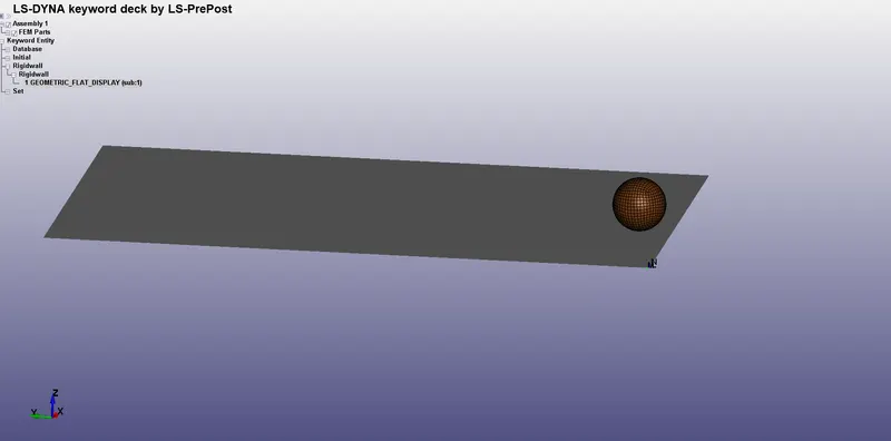
Simple Head model with Rigid Wall
- Simple Head model is assigned the properties of Steel and is created using the MAT_001 card (*MAT_ELASTIC) and the properties of steel is entered in the card as shown below.
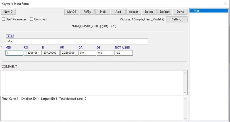
Material definition of the Simple Head part
- The section properties for the simple head are given by using *SECTION_SHELL keyword. All the properties are set to default and a thickness of 1mm is assigned to the shell elements.
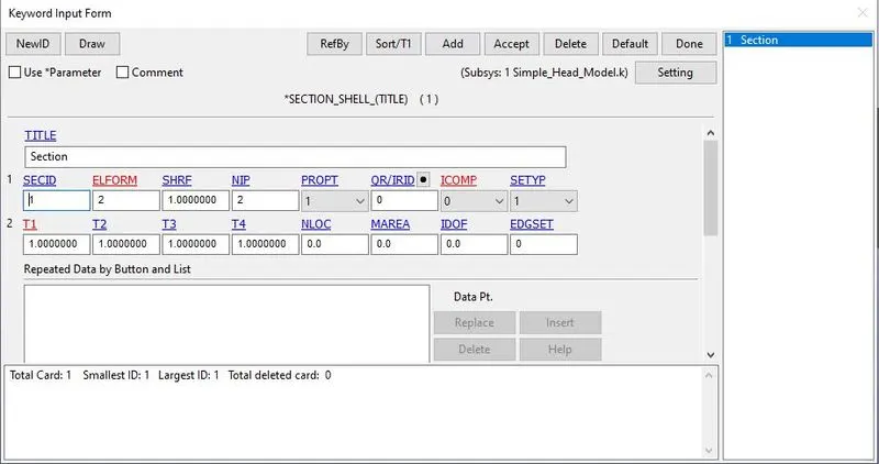
Section definition for the Simple Head part
- The head part is assumed to have 4O kmph (11.11 mm/ms) velocity along the travelling path which is 45 degree measured from the rigid wall. To make the impact of simple head and rigid wall at 45 degrees, a velocity of 7.8559 mm/ms (11.11*cos(45)) is given to the head part along positive X and negative Z directions. The resultant of these velocity vectors gives 40 kmph velocity at 45 degrees measured from the rigid wall.
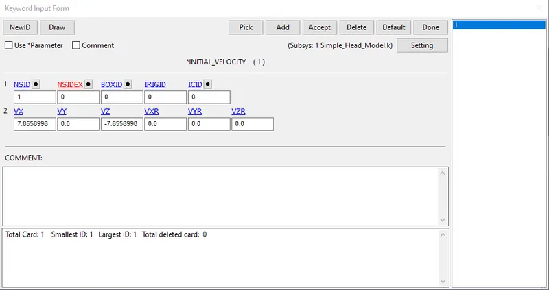
Initial velocity boundary condition definition
- The HIC value is extracted through NODOUT parameter in *DATABASE_ASCII keyword. But for extracting a node statistics, the desired node should be selected in *DATABASE_HISTORY_NODE keyword.
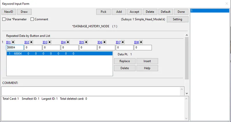
Requesting nodal history variable outputs
- The termination time for the problem is defined by *CONTROL_TERMINATION card. The distance between the head part and the rigid wall is measured and the approximate time it takes to hit the rigid wall is estimated.
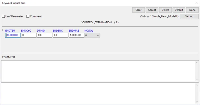
*CONTROL_TERMINATION card
Case II - Child Headform model impact on a Rigid Wall
- In case II, we are increasing the complexity by replacing the simple Head model with Child Headform model.
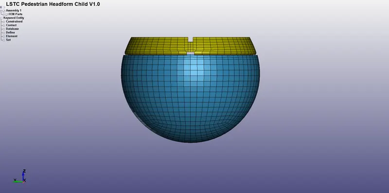
- In this study, head should impact the rigid wall at an angle of 55 degress measured from the rigid wall. But we should not make any changes to the Headform model file.
- The Headform file should be referenced into a separate Main file using *INCLUDE_TRANSFORM keyword since some transformation should be done on the included file.
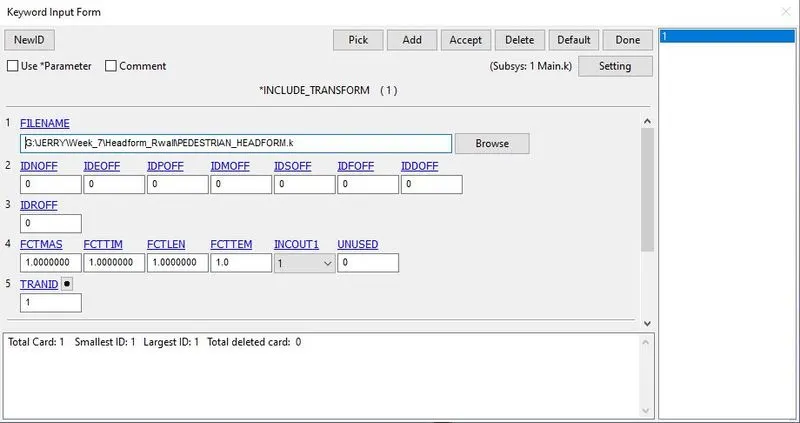
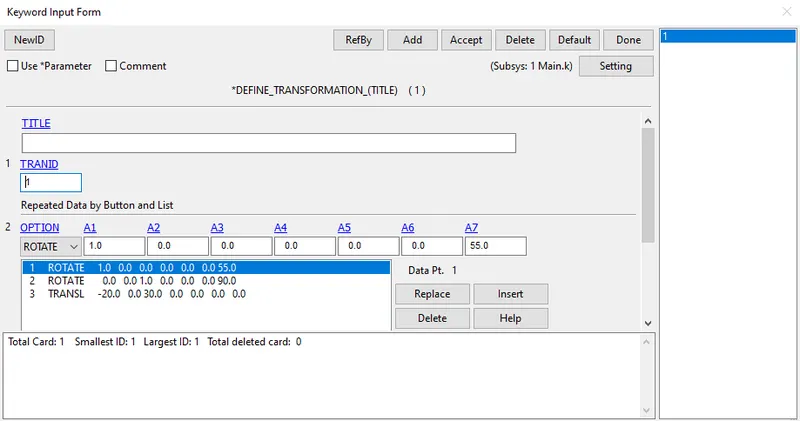
- Before defining *INCLUDE_TRANSFORM keyword, we should define the transformation using *DEFINE_TRANSFORMATION keyword. In this case, the headform model should be rotated 55 degrees about the X-axis.
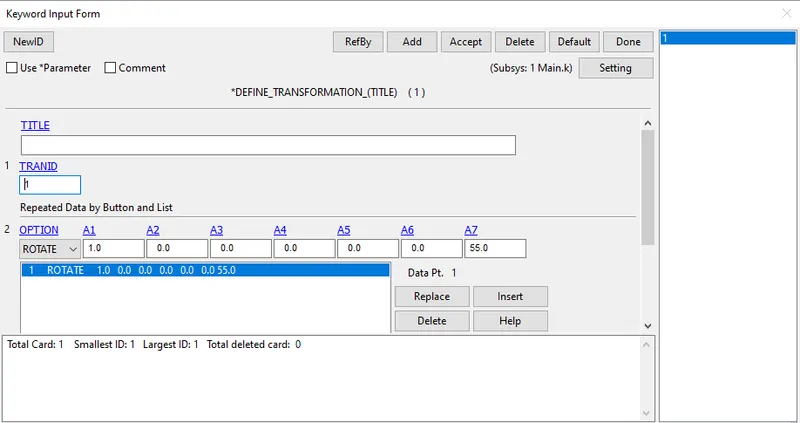
- The original Headform file is not changed but only called for transformation. Further required keywords are added in the Main.k file. Both the Main file and the Child Headform file are kept in the same folder for ease of access.
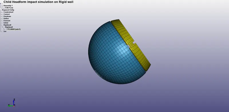
Headform model after transformation
- Next, Rigid wall is generated normal to Z-axis as discussed in the previous case.
- The Headform model contains four parts - Skull, Skin, Accel block and Backplate. All the parts are modelled using solid elements. Only Skin, which is the outermost part is modelled with Ogden Rubber Hyper-elastic material model and rest of the parts are modelled as rigid bodies.
- *CONTACT_AUTOMATIC_SURFACE_TO_SURFACE contact is pre-defined between skull and skin in the Headform model.
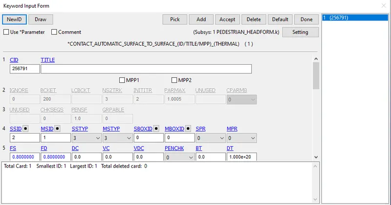
Contact definition between Skull and Skin
- The Headform model has a local co-ordiante system pre-defined in the model. So, the initial velocity boundary condition can be defined with respect to the local co-ordinate system by selecting the co-ordinate system through ICID parameter in *INITIAL_VELOCITY keyword.
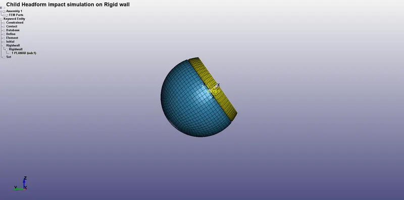
Local co-ordinate system
- Make sure that the keyword is written into Main.k subsystem and not into the Headform subsystem. It is highlighted in the image below.
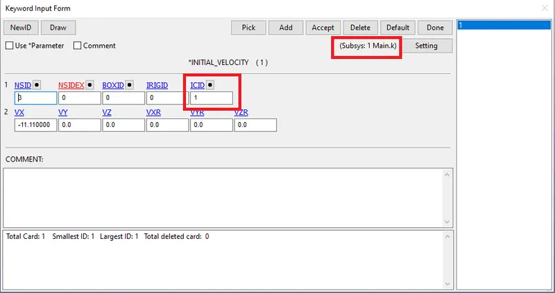
Initial velocity boundary condition definition
- The model after completing the deck preparation is shown below.
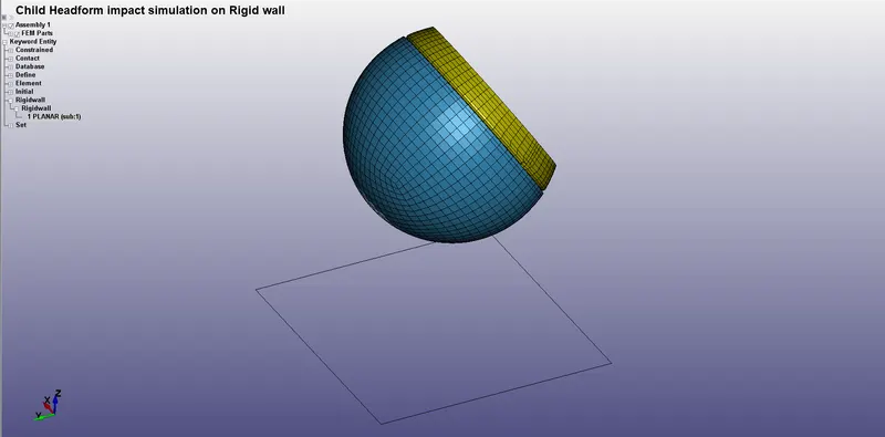
Headform model with rigid wall
- While saving the model, make sure to save all the keywords you created, in the Main.k subsystem. Otherwise, if it is saved in the Headform subsystem, it will change the orientation of the headform model in the Headform file due to the transformation.
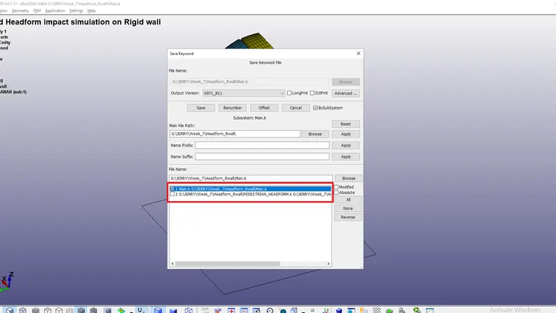
Saving the model
Case III - Child Headform model impact on Hood model
- In this case, we are modelling the Head impact simulation in much more realistic manner by replacing the rigid wall with an actual Hood model.
- First, open a blank model and save it as Main.k file.
- The meshed Hood file is referenced into the Main file using *INCLUDE keyword.
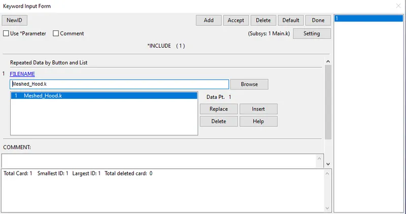
*INCLUDE keyword
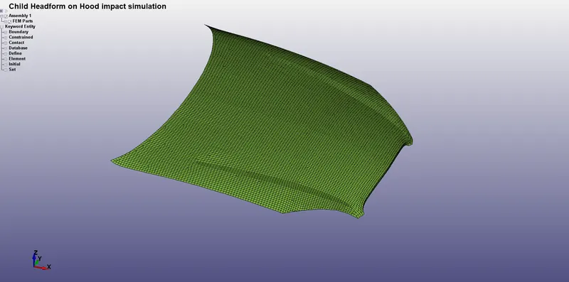
Hood model referenced in Main file after defining *INCLUDE keyword
- The Child Headform file is referenced into the Main file using *INCLUDE_TRANSFORM keyword since the headform model needs to be placed in the correct position with respect to the hood.
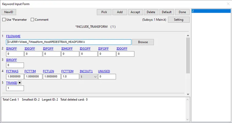
- Before defining *INCLUDE_TRANSFORM keyword, we should define the transformation using *DEFINE_TRANSFORMATION keyword. In this case, multiple transformations are needed to position it correctly with respect to the hood as shown in the image below.
- The Hood and Child Headform model after including in the Main file and after positioning is shown below.
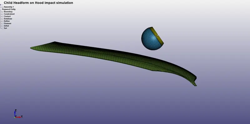
Headform model positioned w.r.t. Hood
- *MAT_PIECEWISE_LINEAR-PLASTICITY material model is assigned for hood and *SECTION_SHELL keyword is assigned along with that. The material properties of aluminium are used to define hood.
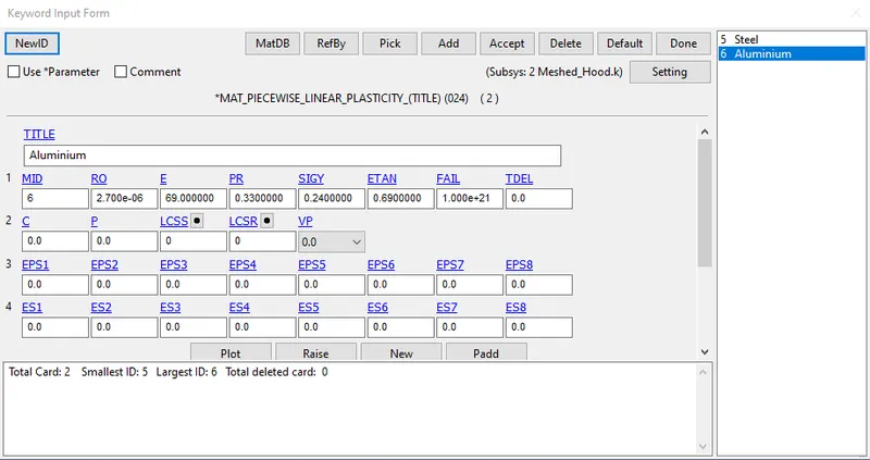
Material definition for Hood
- *CONTACT_AUTOMATIC_SURFACE_TO_SURFACE contact is defined between the hood and Skin part of the Headform model.
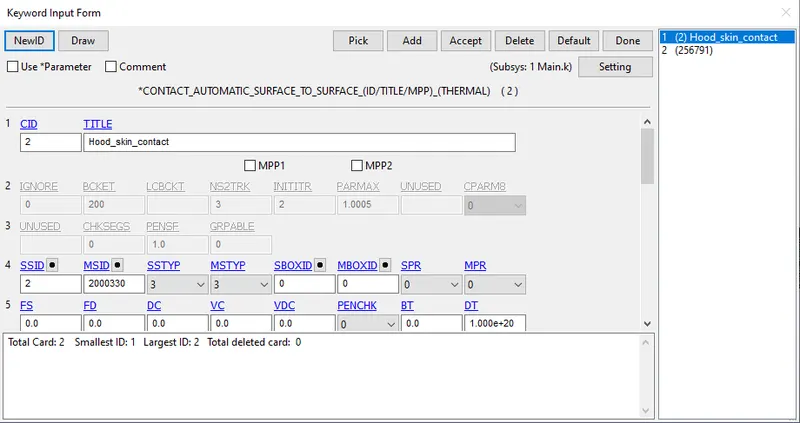
Contact definition between Hood and Skin part of Headform model
- Initial velocity boundary condition is defined in the same way as in the previous case.
- Most of the keywords necessary for simulation have been pre-defined.
- Termination time of 70ms is given to consider the impact and after effect. GLSTAT, RCFORC, SLEOUT, etc. cards are defined to get post-processing results. *DATABASE_EXTEND_BINARY card is used which writes the strain tensor to d3plot. STRFLG is set to 1.
RESULTS AND DISCUSSION :
Effective Stress
Case I - Simple Head model impact on a Rigid Wall
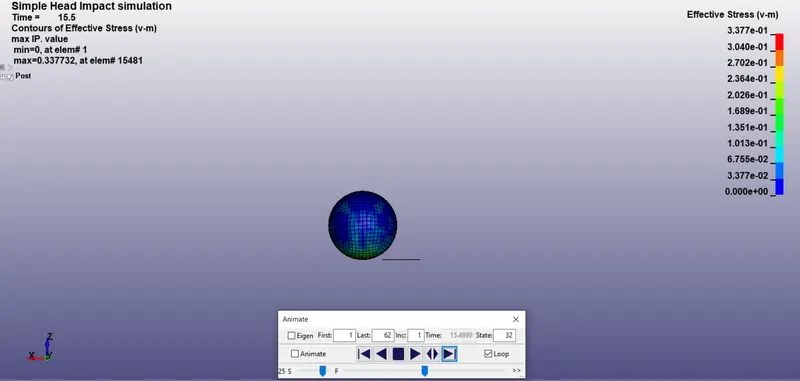
- Max. effective stress of 0.337 GPa (337 MPa) is developed at element number 15481.
- Effective stress element history plot of element 15481 is shown below.
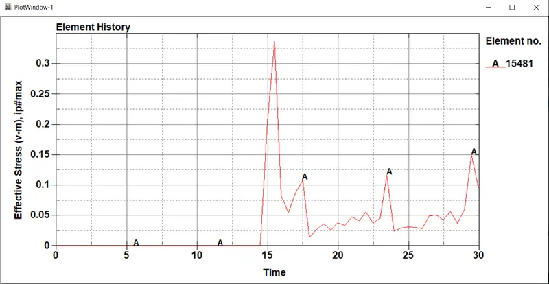
- The stress values are higher at the instant of impact and reduce with fluctuations after the impact as the material is purely elastic. There is no significant deformation in the simple head geometry.
Case II - Child Headform model impact on a Rigid Wall
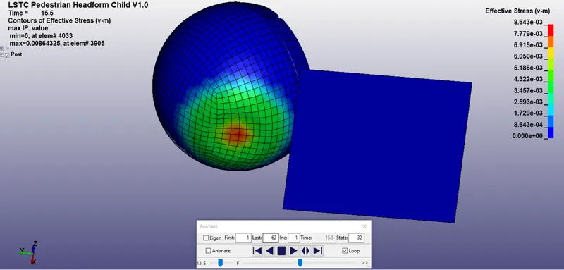
- Max. effective stress of 0.0086 GPa (8.6 MPa) is developed in the Headform model at element number 3905.
- Effective stress element history plot of element 3905 is shown below.
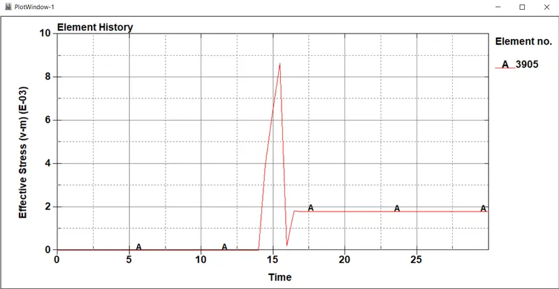
- The material properties for the Child Headform are pre-defined and different from the simple head model. So, it shows different behaviour. There is significant deformation in the geometry after the impact.
Case III - Child Headform model impact on Hood model
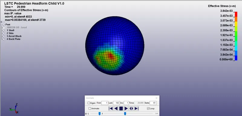
- Max. effective stress of 0.0038 GPa (3.8 MPa) is developed in the Headform model at element number 3739.
- Effective stress element history plot of element 3739 is shown below.
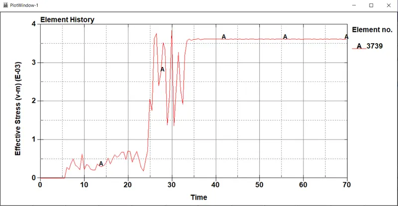
- The hood deforms plastically after the impact and there is less deformation in the head compared to the second case. This is because of the elasto-plastic material which is used to model the hood.
Head Injury Criterion (HIC) plots
- HIC value is generally calculated computationally from the accelerometer mounted at the centre of mass of the crash test dummy (Child Headform in our case).
- For the simple head impact test, a node on the surface was manually selected for extraction of history variable outputs. HIC-36 value is calculated and is basically measured for a time interval less than 36 ms duration and more than 3 ms duration.
Case I - Simple Head model impact on a Rigid Wall
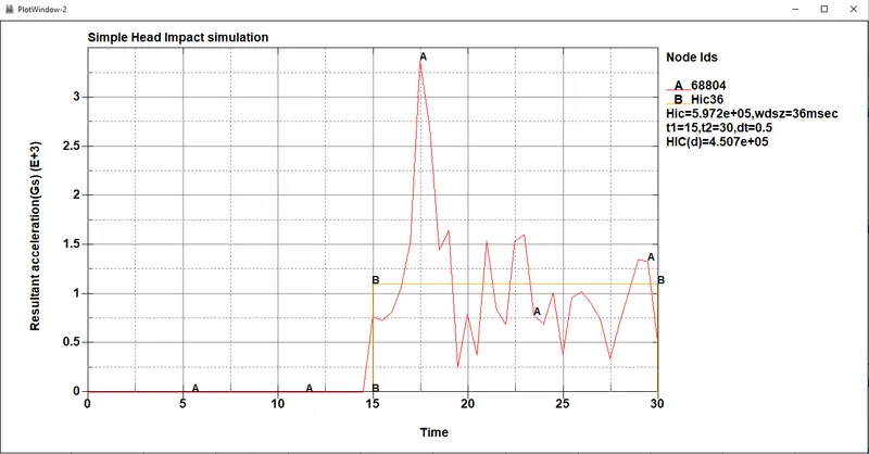
- From the above Acceleration vs. time plot, we can observe that the HIC-36 value for simple head impact case is 5.972e+05 which is not a reasonable value.
- This high HIC value doesn't make any sense because it is a very abstract case with abstract geometrical models, material models and boundary conditions. The purpose of this case was to see how the simulation can be modelled in a simple manner.
Case II - Child Headform model impact on a Rigid Wall
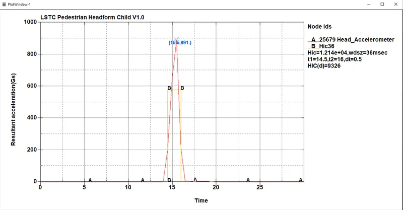
- A HIC-36 value of 1.214e+04 is observed in this case.
- The high value for HIC is due to the abstract modelling for the impactor. The impactor in this case is a rigid wall which is not in the case of a real world pedestrain impact event.
- Since the impactor is a rigid wall, the Headform will experience a high deceleration at the very instant of impact. This high deceleration happens in a very small interval of time which increases the risk of head injury.
Case III - Child Headform model impact on Hood model
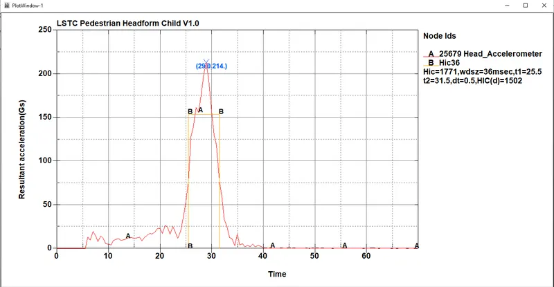
- In this case, we can see a drastic decrease in the HIC-36 value. The obtained HIC value is 1.771e+03 which is one order of magnitude less than the previous case.
- This case can be observed to be more close to realistic results compared to the previous case. This is because in this case, rigid wall is replaced with a Hood model which is able to deform plastically and absorb the kinetic energy of the Headform model.
- As the hood deforms plastically, the reaction force exerted by the hood on the Headform will be much lower in magnitude when compared with the reaction force exerted by the rigid wall. Therefore, the Headform gets more time to decelerate (approximately 10 ms in this case compared to 2 ms in the previous case) which will reduce the risk of head injury.
CONCLUSION :
A study on Pedestrian Head Impact simualtion is carried out to calculate Head Injury Criterion (HIC) value of the impact event. First two cases were very abstract due to approximations in the FE models, material models and boundary conditions. The third case was somewhat close to the actual simulation setup. From the simulation results, the following conclusions can be made :
- The HIC (Head Injury Criterion) is intended to judge the head injury risk quantitatively.
- The larger the value of the deceleration and the longer the deceleration lasts, the higher will be the head load and higher will be the risk of head injury.