Project 1 - 2D meshing on the instrumental Panel
AIM :
To mesh the Automotive Instrument Panel Console using ANSA according to the below-mentioned quality criteria and assign the thickness to the whole model.
The quality criterion to be followed:
|
S.No |
Quality Criteria |
Value |
|
1 |
Target/Average length |
4 |
|
2 |
Minimum Length |
2 |
|
3 |
Maximum Length |
6 |
|
4 |
Aspect |
3 |
|
5 |
Warpage |
15 |
|
6 |
Skewness |
45 |
|
7 |
Jacobian |
0.7 |
|
8 |
Minimum Quad Angle |
45 |
|
9 |
Maximum Quad Angle |
135 |
|
10 |
Minimum Tria Angle |
30 |
|
11 |
Maximum Tria Angle |
120 |
|
10 |
Tria Percentage |
15 |
INTRODUCTION :
The automotive NVH requirement is getting higher and higher with the developing of automotive industry. Vibration of the key components in the car has a high contribution to the NVH performance of the whole vehicle. Instrument panel (IP), as the largest inner trim parts which directly shown to passengers, have not only beauty and function requires but also NVH and safety request. The vibration and noise on dashboard can be directly feel by passengers. Thus the modal analysis of instrument panel plays an important role in NVH character of the whole vehicle. CAE analysis is a very efficient way to study the NVH character. As it can help shorten the test cycle and reduce development cost, CAE analysis is widely used during automotive development procedure.
Automotive Instrument Panel Plastic Trim
PROCEDURE :
Import model
- Firstly, we need to import the model and study geometry.
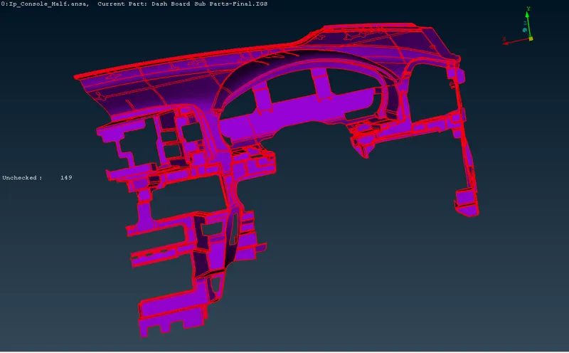
Imported IP CAD model
Geometry cleanup
- After importing geometry into the ANSA environment we observe many topological errors while doing the geometry checkup as shown below.
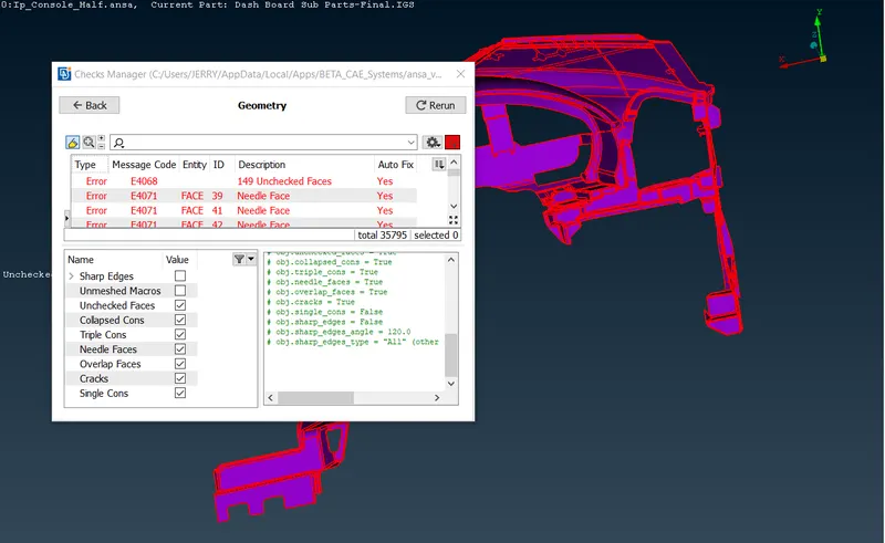
Geometry checks of the CAD model
- You can use the hybrid option to minimize your time consumption by auto fixing most of the areas and rest by manual fixing.
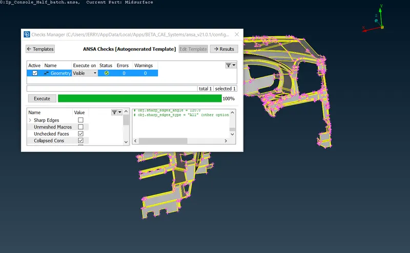
Geometrical check after cleanup
- Next, we have to measure the thickness throughout the part. If thickness changes are observed then all surface regions having uniform thickness has to be kept under a separate PID.
Orientation
- Orientation must be checked thoroughly by the user every time working on a model.
- All models should have the correct orientation because the orientation issue will cause the final time issue when you merge the model with a complete vehicle. It is always preferred to maintain the continuity over the surface either grey or yellow throughout the face.
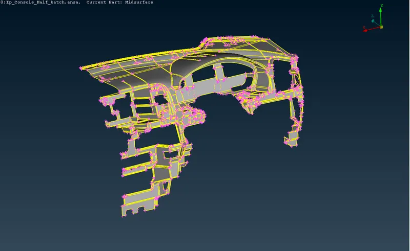
Orientation continuity over the CAD model
Midsurface generation
There are two way to extract mid surface :
- Manual mid-surface method
- Auto mid-surface method
Manual mid-surface generation
- This can be done by manually selecting the surface and giving an offset option in the direction opposite to the grey surface using TOPO -> Faces -> Offset option.
Auto mid surface generation
- If the geometry is closed then we can go for auto mid-surface generation option but it will auto-delete the parent geometry.
- Press the Mid.Surface option under Face tab.
- Select the full geometry and confirm the mid location.
- Here I have used the manual offset method extract mid surface as the surface thickness varies and ANSA is unable to segregate separated surfaces for auto mid surface generation.
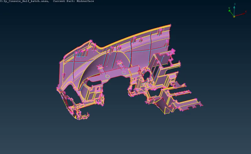
Mid-surface of the Instrument Panel
Meshing
- After midsurface generation, the surface is cleaned up before meshing so that the mesh should not fail for the given conditions, i.e., min. size, warpage, etc.
- Unnecessary feature lines are toggled off in order to minimize the quality criteria errors like minimum size, warpage, etc. Feature lines are toggled using TOPO module -> Faces -> Cut tool and right clicking the con to be toggled off.
- Meshing is done using the MESH module. All the meshing tools are arranged in the MESH module.
- The first step in meshing is to set the perimeter and macro length to the target element size using MESH module -> Perimeters -> Length tool.
- After that, mesh parameters have to be defined in Mesh Parameters option in Utilities menu. The main parameters include Target length, Min. Target length and Max. Target length.
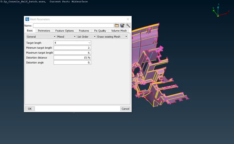
Mesh Parameters window
- So now we can start meshing the component individually but before we start meshing we will know about the 2D meshing and its good practices to follow to get a good mesh flow.
2D Meshing / Shell Meshing
The type of element allowed in 2D meshing are :
- Quad Elements
- Tria Elements
Best practices to follow to get better mesh flow
- Back to back tria element should be avoided.
- On a planar surface, tria should be avoided by merging them using Split, Swap or Join option.
- No mesh transition on radius fillets/curvatures.
- Hole feature should be captured with even-numbered equally spaced elements.
- Avoid Trias at edges and on the features and construction lines.
- Rotating Quads are not preferred.
- Constant mesh size is preferred due to min. element length and time step criteria.
- Remove the redundant and excess construction line to get uniform mesh flow.
- Divide the surface near the feature to get better mesh flow pattern.
- Defeature the areas which are going to fail for the quality criteria.
- Now we can finally start meshing the component and can get the better mesh flow by keeping in mind the best practices followed in meshing.
- Meshing is performed using MESH module -> Mesh Generation -> Best/Spot Mesh/Free tool keeping the target element size as 4 mm.
- The mesh generated is further refined by reconstructing the selected elements using Reconstruct tool in the Shell Mesh button.
- After the mesh got reconstructed properly, the mesh is smoothed to ensure proper mesh flow using Smooth tool in Shell Mesh button in MESH module.
Quality Check
- Quality criteria needs to be set in the Quality Criteria tool in the Utilities menu.
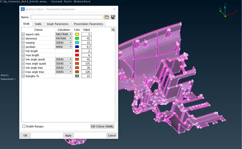
Quality Criteria window
- The quality of the mesh is seen when the drawing style is changed to Hidden mode.
- Failed elements need to be manipulated and should be cleared for the quality criteria.
Assigning thickness
- Property card is created for each surface since the thickness is different for each rib surface.
- Thickness is entered in the property card and the property is assigned to the corresponding surfaces.
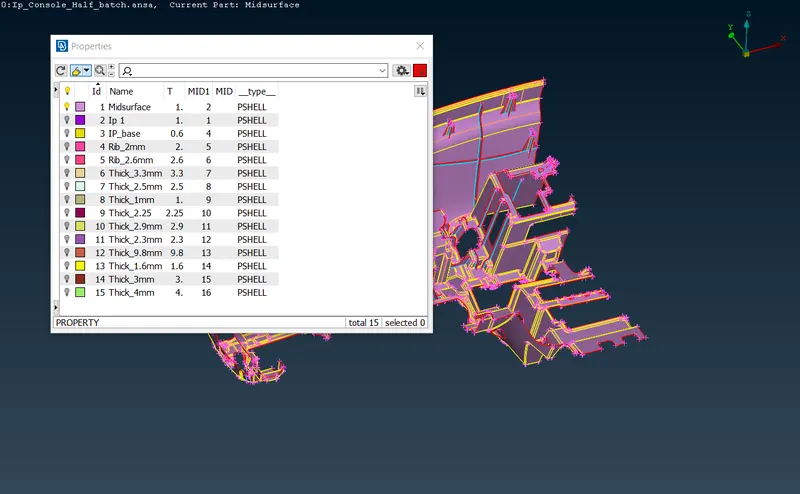
Properties window
RESULTS :
- The Instrument Panel console model is meshed part by part according to the quality criteria.
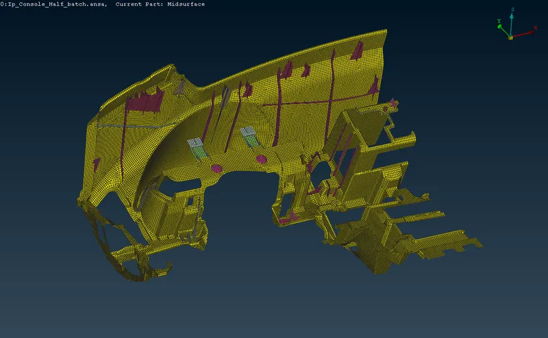
Meshed Instrument panel
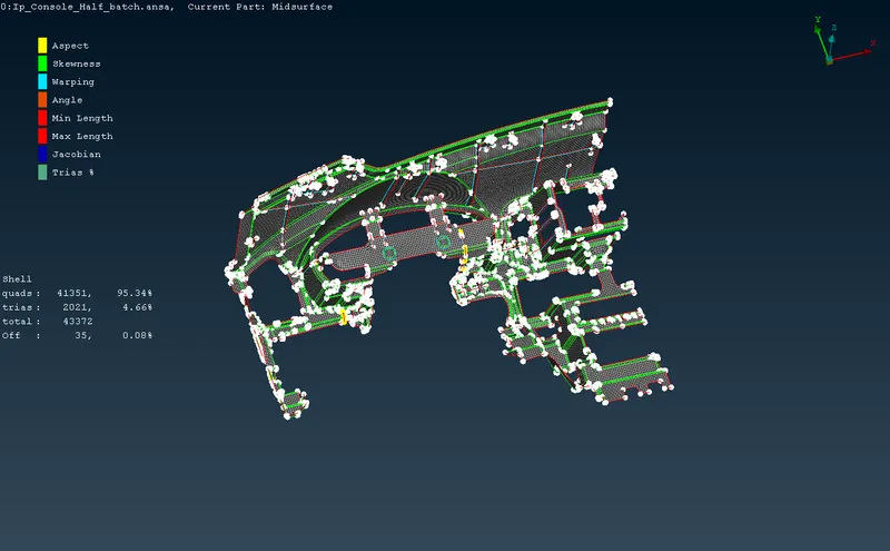
IP mesh in HIDDEN view mode
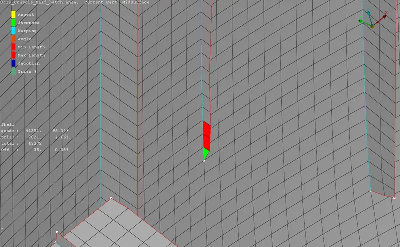
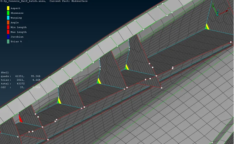
Feature capturing difficulty and failing elements regions
- Elements failing for Min. Length and Skewness at Ribs
- Elements failing for Min. Length, Aspect Ratio and Skewness near the extended rib region
CONCLUSION :
The Instrument Panel model is meshed according to the quality criteria and assigned proper thickness to the mesh. The panel had been captured quite a well-using shell mesh. The total number of elements 43,372 out of which 2021 are Tria element and 41,351 are Quads which makes 4.66% which is a decent percentage of Tria elements. Also, 35 elements are failing as shown above. The final meshed model is attached with this report.
LEARNING OUTCOME :
- Able to fix topological error.
- Able to generate mid surface for any complex geometry.
- Able to understand and implement good practices of meshing any complex geometry.
- Competent in 2D meshing/ shell meshing even for complex geometry by achieving better mesh flow.