Week - 5 - Modelling Spotwelds
AIM :
To model spotwelds using Beam and Solid elements to connect the two parts of the crash box and compare the two and simulate a crash test for the crash box model.
The following outputs are to be requested from the simulation:
- Animation of the final simulation
- Cross-sectional force generated in the middle of the crashbox (along its length)
- Maximum directional stress and strain along the length of the crashbox (X strain, Y strain etc)
- Plot of all energies (total, internal, kinetic, hourglass, sliding)
- Comparison of axial and shear force between the beam and solid spotwelds.
TOOLS REQUIRED :
- LS-PrePost
- LS-Run
THEORY :
*MAT_SPOTWELD (*MAT_100)
This material model applies to beam element type 9 for spot welds. These beam elements may be placed between any two deformable shell surfaces, and tied with type 7 constraint contact which eliminates the need to have adjacent nodes at spot weld locations. Beam spot welds may be placed between rigid bodies and rigid/deformable bodies by making the node on one end of the spot weld a rigid body node which can be an extra node for the rigid body. In the same way, rigid bodies may also be tied together with this spot weld option.
It is advisable to include all spot welds, which provide the slave nodes, and spot welded materials, which define the master segments, within a single type 7 tied interface. As a constraint method, multiple type 7 interfaces are treated independently which can lead to significant problems if such interfaces share common nodal points.
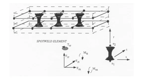
The weld material is modeled with isotropic hardening plasticity coupled to two failure models. The first model specifies a failure strain which fails each integration point in the spot weld independently. The second model fails the entire weld if the resultants are outside of the failure surface defined by:

where the numerators in the equation are the resultants calculated in the local coordinates of the cross section, and the denominators are the values specified in the input. If the user defined parameter, NF, which the number of force vectors stored for filtering, is nonzero the resultants are filtered before failure is checked. The default value is set to zero which is generally recommended unless oscillatory resultant forces are observed in the time history databases. Even though these welds should not oscillate significantly, this option was added for consistency with the other spot weld options. NF affects the storage since it is necessary to store the resultant forces as history variables.
If the failure strain is set to zero, the failure strain model is not used. In a similar manner, when the value of a resultant at failure is set to zero, the corresponding term in the failure surface is ignored. For example, if only F Nrr is nonzero, the failure surface is reduced to |Nrr| = NrrF . None, either, or both of the failure models may be active depending on the specified input values.
PROCEDURE :
- The given Keyword file spotweld-assignment.k is opened in LS-PrePost using File -> Open -> LS-DYNA Keyword File option.
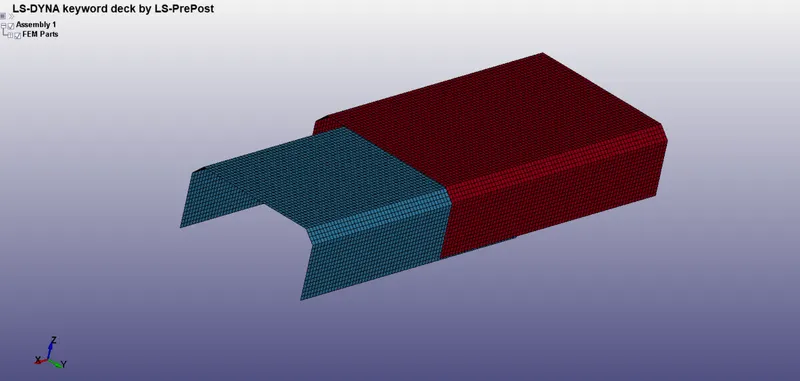
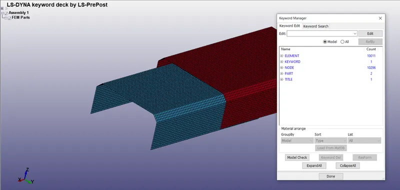
- If we check the Keyword Manager in the Model and Part option, we can see that only nodes and elements are present in the model. We need to build the complete deck from the mesh.
- First, material has to be created for the crashbox.
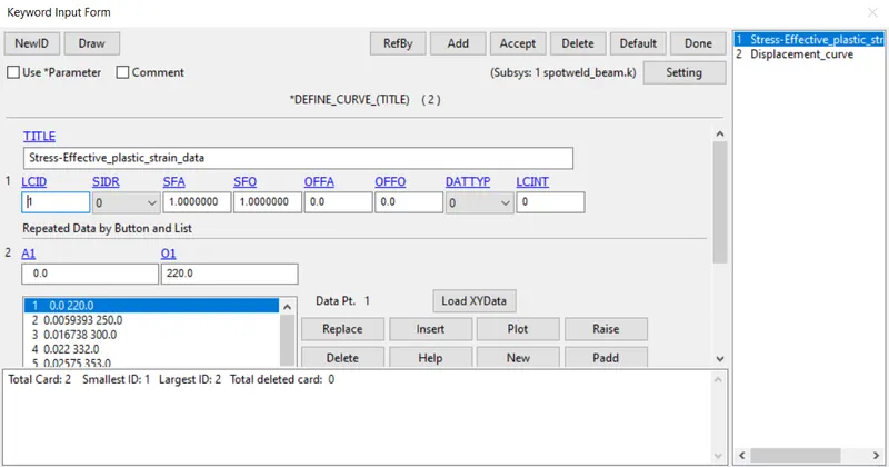
- Crashbox is assigned the properties of Steel and is created using the MAT_024 card (*MAT_PIECEWISE_LINEAR-PLASTICITY) and the properties of steel is entered in the card as shown below.
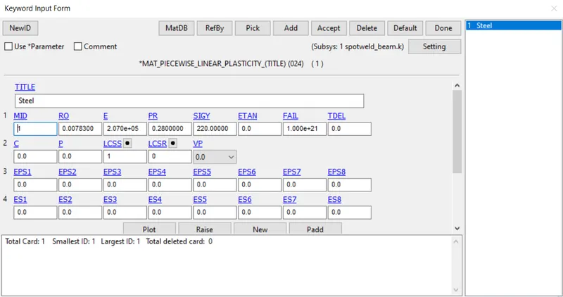
- The plastic region of the material data is modelled using a curve of Stress vs. Effective plastic strain and it is defined using *DEFINE_CURVE keyword. The defined curve is referenced into the material card using LCSS option.
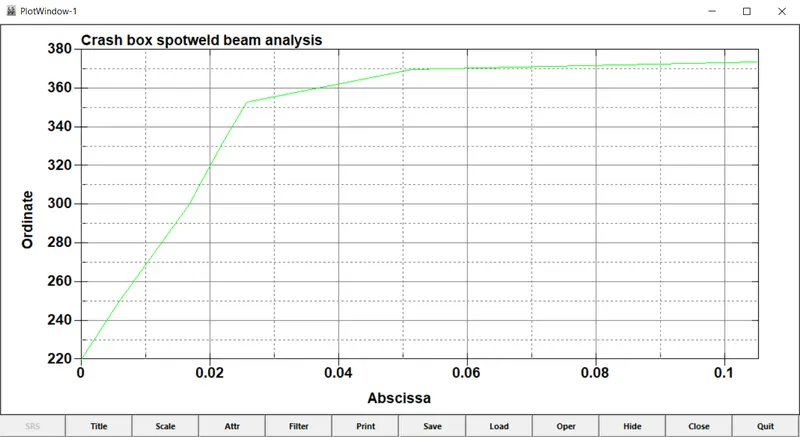
Stress vs. Effective Plastic Strain plot
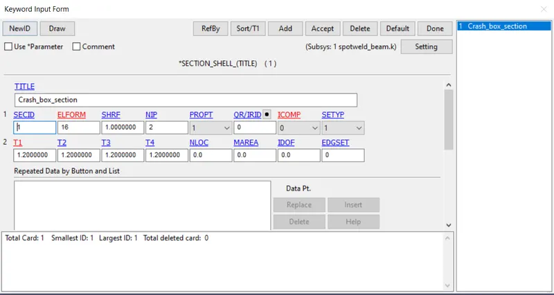
- Section is created for the crashbox. As it is modelled with shell elements, *SECTION_SHELL is used with default element formulation of 2.
- Since it is a shell section, thickness of the crashbox have to be defined in the section keyword.
- Required Boundary condition is applied on the model.
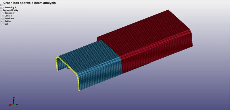
- Single point constraint is applied on one end of the crash box locking all 6 DOFs using *BOUNDARY_SPC_SET keyword as shown below.
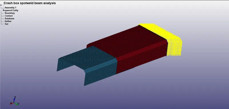
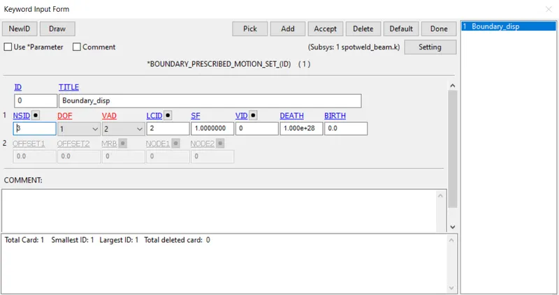
- Prescribed Motion Displacement boundary condition is applied to the other end of the crash box using *BOUNDARY_PRESCRIBED_MOTION_SET keyword by defining displacement curve explicitly through *DEFINE_CURVE keyword.
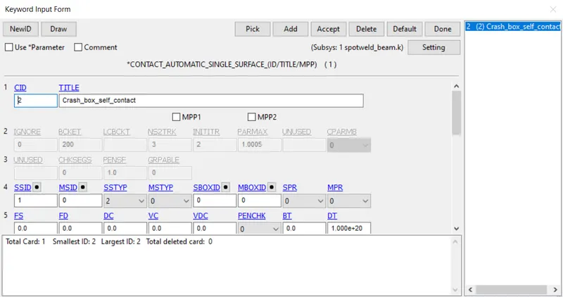
- As the crashbox undergoes deformation, there are chances that the box will come into self contact. For avoiding self penetration, *CONTACT_AUTOMATIC_SINGLE_SURFACE keyword is created to handle self contact by creating a part set for the two parts.
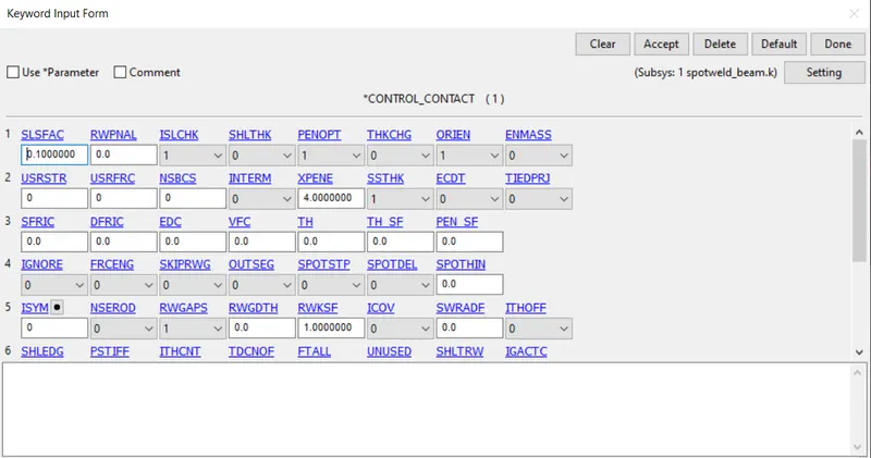
- An additional *CONTROL_CONTACT keyword is defined to use actual thickness in the contact. SSTHK =1 activates this option.
- A cross-section has to be created to find out the force transmitted through the crashbox.
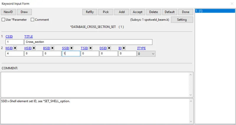
- Cross-section is created using *DATABASE_CROSS_SECTION_SET keyword.
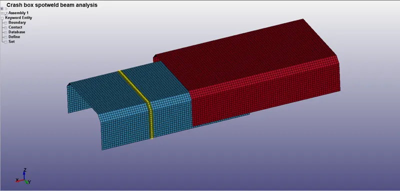
- A node set containing the nodes of the cross-section and an element set containing one row of elements on either side of the section is created to define the cross-section.
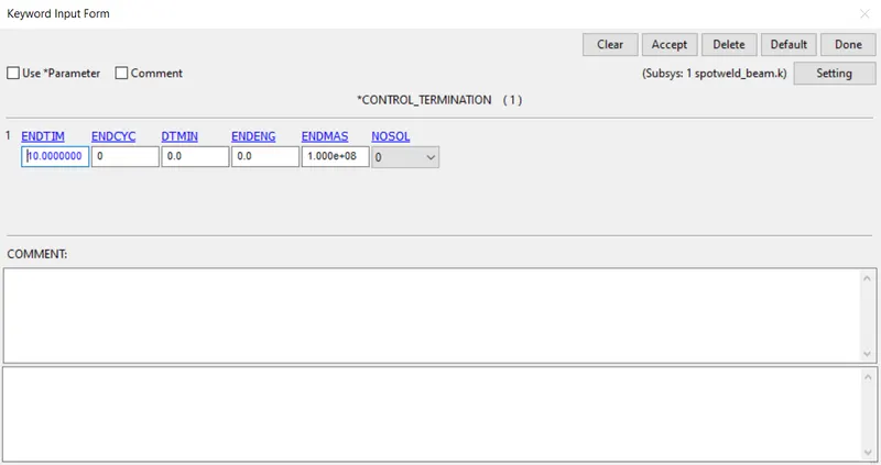
- The termination time for the simulation is input in the *CONTROL_TERMINATION card as shown below.
- At last, the required outputs should be requested using *DATABASE card.
- *DATABASE_ASCII_option - Outputs such as Global Statics (GLSTAT), Spotweld force (SWFORC), Resultant interface forces (RCFORC), Sliding Interface Energies (SLEOUT), Cross section forces (SECFORC) are requested.
- *DATABASE_BINARY_D3PLOT - Animation file is requested using this card.
- *DATABASE_EXTENT_BINARY - Strain results are requested to the animation file using this card.
Case -1
- In this case, spotwelds are created using Beam elements.
- Beam elements are created using Element Tools -> Element Editing tool by selecting two nodes where beam elements have to be created.
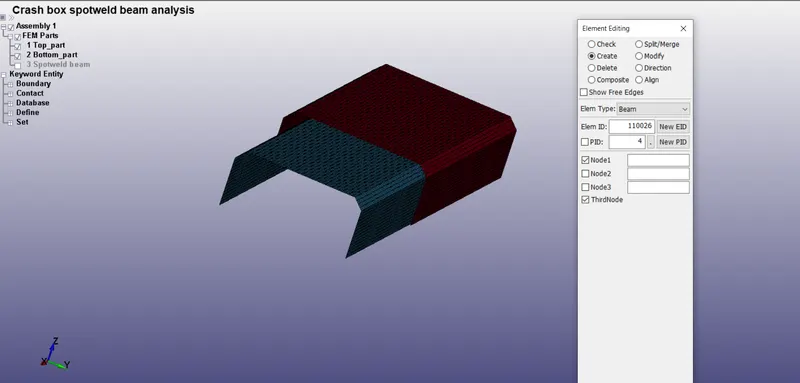
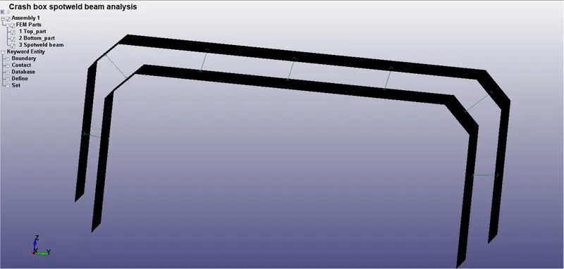
Created Beam elements
- Material has to be created for the Spotweld beam elements.
- Beam elements are assigned the properties of Steel and is created using the MAT_100 card (*MAT_SPOTWELD) and the properties of steel is entered in the card as shown below.
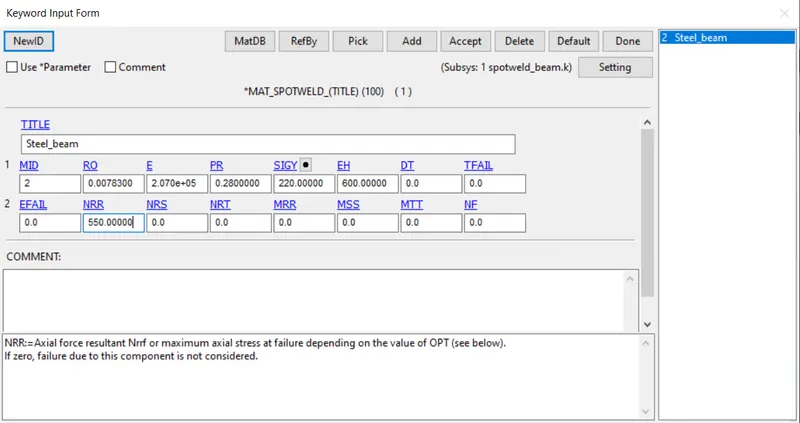
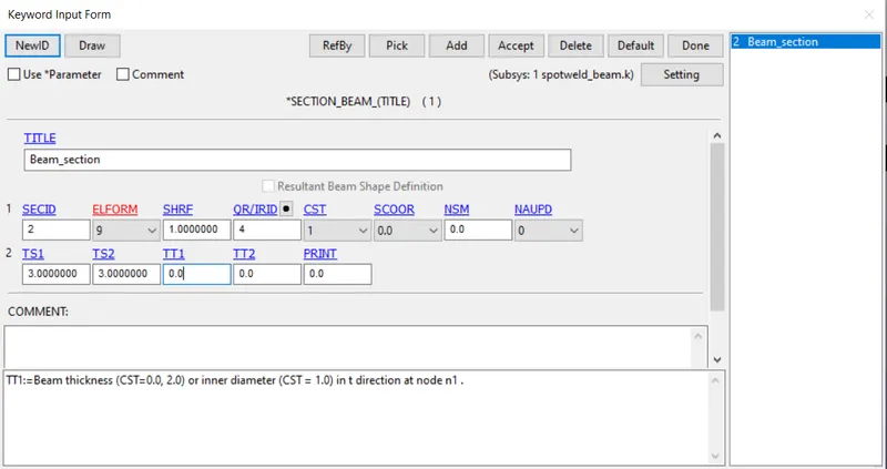
- Section is created for the beam elements. As it is modelled with beam elements, *SECTION_BEAM is used with element formulation of 9 which is to be used with *MAT_SPOTWELD material.
- Since it is a beam section, outer diameter of the beam element have to be defined using TS1 and TS2 parameters in the section keyword.
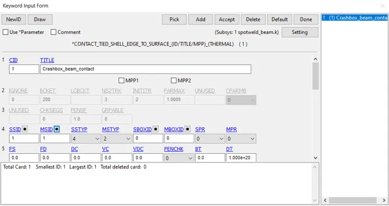
- Next, contact have to be defined between the crashbox and the beam elements using *CONTACT_SHELL_EDGE_TO_SURFACE keyword with beam elements as slave and crash box parts as master.
Case - 2
- In this case, spotwelds are created using solid hexa elements.
- Solid elements are created using Element Tools -> Element Editing tool by selecting eight nodes where solid elements have to be created.
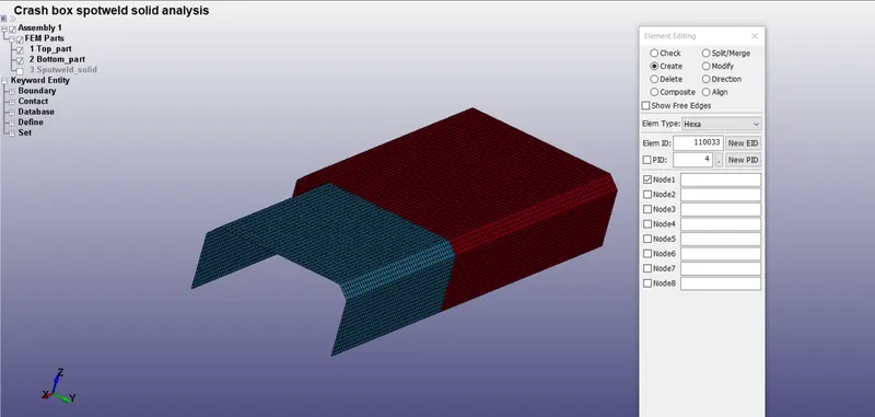
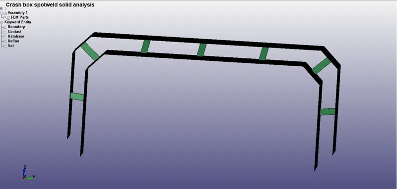
Created solid elements
- Material has to be created for the Spotweld solid elements.
- Solid elements are assigned the properties of Steel and is created using the MAT_100 card (*MAT_SPOTWELD) and the properties of steel is entered in the card as shown below.
- Section is created for the solid elements. As it is modelled with solid elements, *SECTION_SOLID is used with default element formulation of 1.
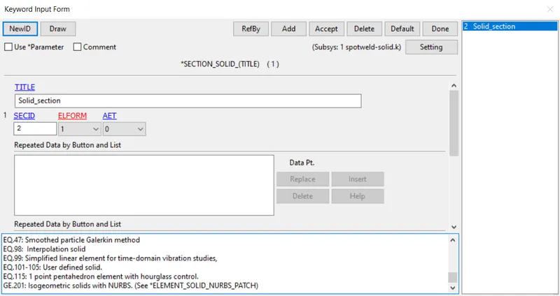
- Next, contact have to be defined between the crashbox and the solid elements using *CONTACT_SPOTWELD keyword with solid elements as slave and crash box parts as master.
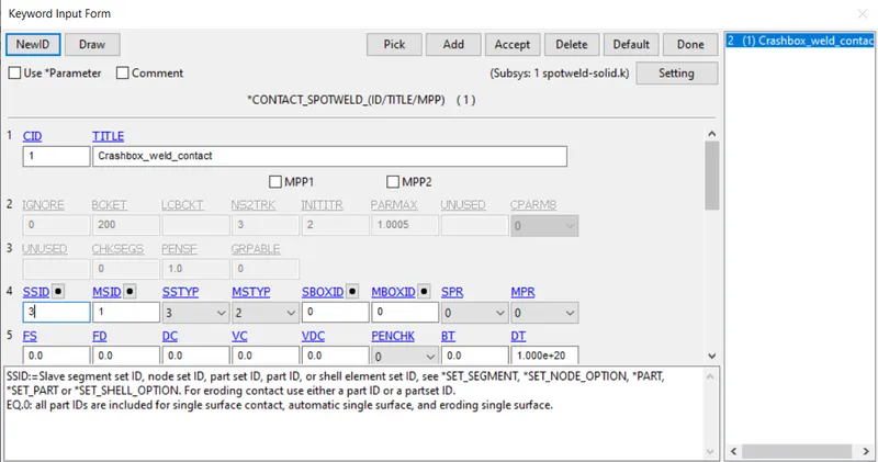
- All the necessary cards are created. The file is submitted to the solver for solving the problem.
RESULTS :
The animation files are attached with the report.
X-directional Stress
- The X-directional stress contour plot for Beam spotweld case is shown below.
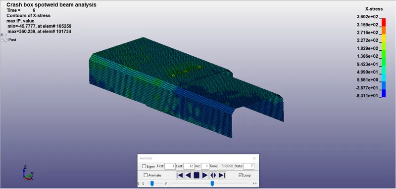
- A max. tensile X-stress of 360 MPa is developed at element number 101734 at time = 6 ms.
- The X-directional stress contour plot for Solid spotweld case is shown below.
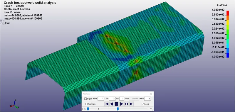
- A max. tensile X-stress of 405 MPa is developed at element number 109905 at time = 4 ms.
X-directional Strain
- The X-directional strain contour plot for Beam spotweld case is shown below.
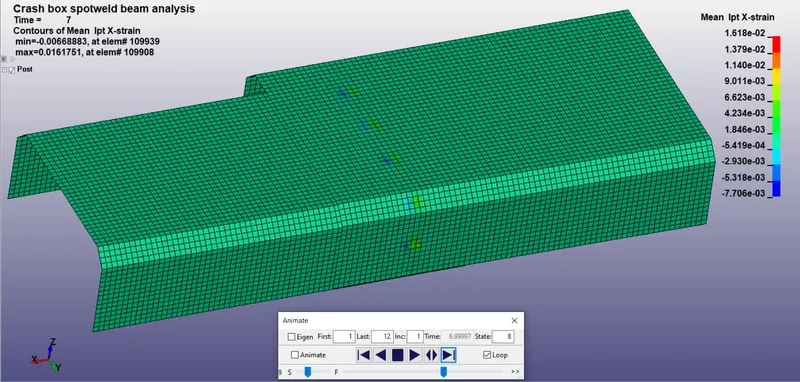
- A max. X-strain of 0.01618 is developed at element number 109908.
- The X-directional strain contour plot for Solid spotweld case is shown below.
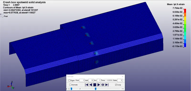
- A max. X-strain of 0.07764 is developed at element number 110027.
Global Energy plot
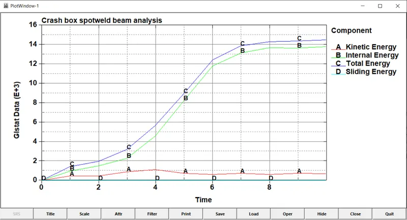
- The global energy plot for Beam spotweld case is given below.
- The global energy plot for Solid spotweld case is given below.
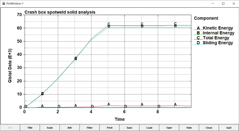
- Crashbox simulated with Beam spotweld was able to absorb 14,000 N-mm of energy before failure of all spotwelds, whereas the crashbox simulated with Solid spotweld absorbed 60,000 N-mm of energy.
- The system with solid spotwelds absorbed high internal energy compared to beam spotweld because the solid spotweld is connected to four shell elements on one side. So, the shell elements will undergo more deformation since the spotweld has a contact area in reality. In beam spotweld case, the beam element was connected only to one node on one side which is not realistic. Therefore, the crashbox takes up more internal energy when modelled with solid spotwelds.
Cross-section Force
- Cross-sectional force plot for Beam spotweld case is shown below.
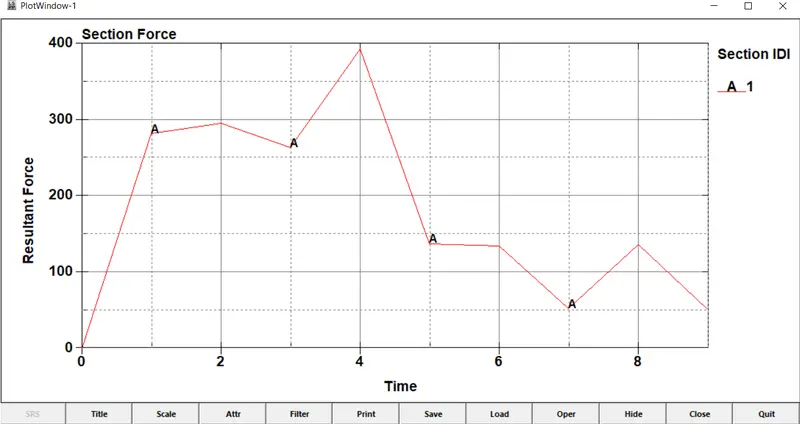
- A max. section force of 393 N is developed at the selected section.
- Cross-sectional force plot for Solid spotweld case is shown below.
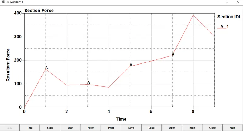
- A max. section force of 393 N is developed at the selected section.
Axial and Shear force
- Force plot for one of the beams in Beam spotweld case is shown below.
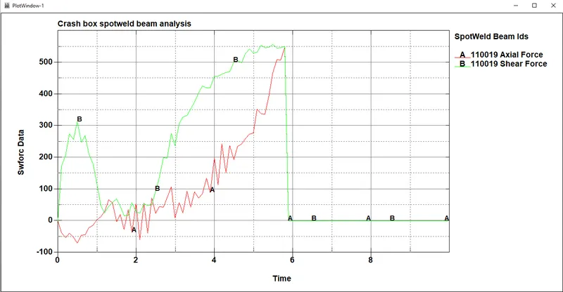
- From the plot, we can see that the spotweld fails when the axial force in the beam element reaches 550 N which is what expected from the input we have given in the *MAT_SPOTWELD card.
- Force plot for the Hexa element at the same location (as in the beam element case) in Solid spotweld case is shown below.
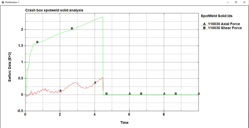
- From the plot, we can see that the hexa spotweld elements fails in less time compared to the beam element case.
- Since the solid element has only translational DOFs, we can see a high shear force in hexa spotweld compared to beam spotweld.
CONCLUSION :
Deck preparation is carried out for the Spotweld simulation using beam as well as solid hexa elements including all the necessary keywords. The following conclusions are drawn from the carried out spotweld analysis :
- Spotwelds modelled using solid elements seems more realistic in behaviour since in actual weld, the weld has a definite area of contact with the parts being connected which is not considered in modelling using beam elements.
- Thus, for an abstract modelling of spotwelds, we can model the spotweld using beam elements. If our aim of analysis is purely focussed on the behaviour of spotwelds, we should model it using Hexa elements which is more close to real world scenario.
The prepared deck file is attached with this report.