Week 6 - Creating connection for Rear door
AIM :
To implement connections for a Rear Door FE model.
TOOLS REQUIRED :
- ANSA
THEORY :
There are mainly 5 types of connection
- Weld
- Adhesives
- Bolt
- Area contact
- Replace part
1D Element
1D elements are used when one of the dimension is very large compared to the other two.If a large number of bolts are to be modeled, then the use of solid element representation can be far too burdensome in terms of setup time, contact complexity, and computational cost. An alternative is to use a 1D beam element representation. This can also use a similar preload method. There are many different implementations of this approach, but we will focus on a method which uses a rigid element to spider out the head and nut tend of the bolt to the top and bottom plate respectively, and can connect to 2D or 3D element representation
They are simply the connection between nodes. There are few working elements majorly used:
- a) Non-rigid Links
- CROD
- CBAR
- CBEAM
- b) Rigid Links
- RB2
- RB3
CROD:
- This element only 'understand' "tension & compression" loads (only axial force only).
- They only have translational DOF.
- But still, this element has a torsional stiffness.
CBAR:
- Simple beam with constant properties (symmetrical and constant cross-section).
- Shear center and neutral axis should consider, any offset between the neutral axis and the shear center is not accounted
- Not useful to model beam that warps (open channel section).
CBEAM:
- The cross-sectional properties are tapered.
- The neutral axis and shear axis does not coincide
- The effect of cross-sectional warping on torsional stiffness is critical
- The difference in the mass center of gravity and shear center is significant.
Rigid Elements
A rigid element is a link from one node to one or more other nodes, where the motion of the node(s) is governed by the "degrees of freedom" you choose to connect. A rigid element is actually a constraint equation rather than an actual element.
- Bolt pre-load at a critical interface needs to be modelled, but does not need the bolt to be modelled with any more detail than as a "bar" or "beam" element. An RBE2 can be used to connect the end node of the "bolt" element to the multiple nodes which represent the washer area over which the bolt load acts.
- To model the dynamic behavior of a vehicle, the engine can be modelled as a mass element connected by an RBE2 rigid element to the engine's multiple mounting locations. This makes the reasonable assumption that the engine is "very stiff" compared to the body structure and so the engine does not need to be modelled in detail. The mass is located at the centre of gravity of the engine, and the rigid element links the engine mass to the rubber mounts (eg. springs or bushes) whose stiffnesses are typically much more relevant.
RB2: Rigid link to transfer motion from the independent node to the dependent node(s).
RB3: Rigid link to distribute loads and will not induce any stiffness.
Note:
- Both elements "look" the same, in that they have a single node connected to one or (usually) multiple other nodes. The difference is that the RBE2 element adds (infinite) stiffness to the structure, while RBE3 elements "distribute forces" around the connected nodes, without adding any stiffness.
Connectors
These are the geometrical representations of the connection between the entities. The advantage of connectors is the ability to create multiple connections at a single time.
Spot
- Connection at a point
- Spot weld, rivet, etc.
Bolt
- Connection at the hole locations.
- Eg. Bolts
Seam
- Connection along the length
- Seam weld
- Connect geometry only
Area
- Connection of areas
- Adhesives
Role of a seal in the NVH behavior of a car
Automotive weather seals are typically dual extrusion bulbs of sponge and dense rubber that are attached to either the door or the car body in order to seal the passenger compartment. The seals can be held in place in several manners, e.g. intermittent pushpins, continuous carriers, etc., and have a vast variety of shapes with a height of approximately 10-30 mm. The seal wall thickness is typically a few millimeters to provide a maximum sealing area at a low compression force.
The seal strip induces some residual stiffness and viscoelastic contribution to the door support conditions and plays a role in the way exterior noise and vibration can be transmitted to the interior of the car. The initial use of seals in automotive applications was aimed at accommodating construction variations.
Lately, the isolation issue became important, and the design was oriented to better isolate the passenger compartment from dust, water, and air leakage. Nowadays the general trend in seal design is mainly oriented on the isolation of the passenger compartment from noise and vibration. For automotive applications the material requirements aspect, such as resilience, weather resistance (including ultraviolet radiation effects), bonding strength, tear, abrasion resistance, etc. also need to be considered when designing for optimal weather seals.
At a certain driving speed, the pressure difference between the interior and the exterior of the car pushes the seal outward. If the resultant pressure is higher than the frictional forces at the contact area, separation occurs. The occurrence of separation is influenced by the compression rate and the friction coefficient of the rubber to the metal contact area. When separation occurs, an open path for direct noise is created and turbulence at the door edge is generated. The turbulence is due to the interaction between the escaping air fluxes from the passenger compartment, encountering the air fluxes at the exterior of the car.
The damping, stiffness, and the mass distribution influence the car door vibration levels and the mechanism of energy transmission from the door to the car body. The support and isolation characteristic of the seal becomes important performance factors that should be taken into account in seal design and analysis.
PROCEDURE :
- The given Rear door model is opened in ANSA using File -> Open option.
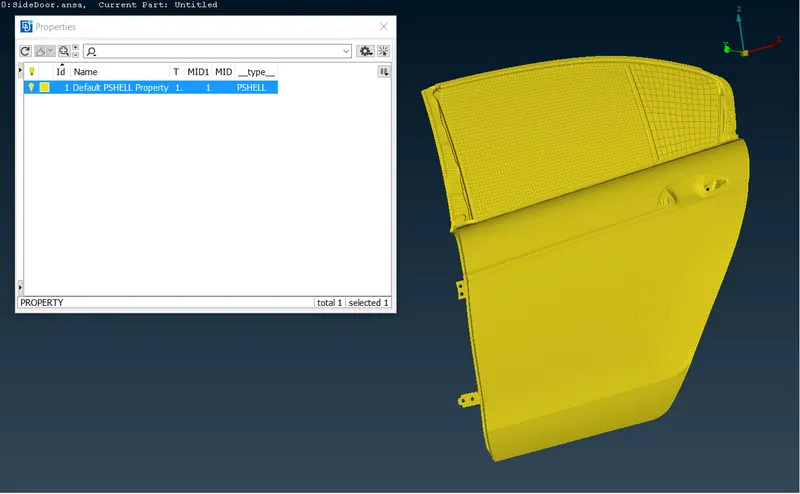
Rear Door model
- When opened, the whole model was under one single PID. Therefore, the different parts of the model are arranged in separate PIDs as shown below.
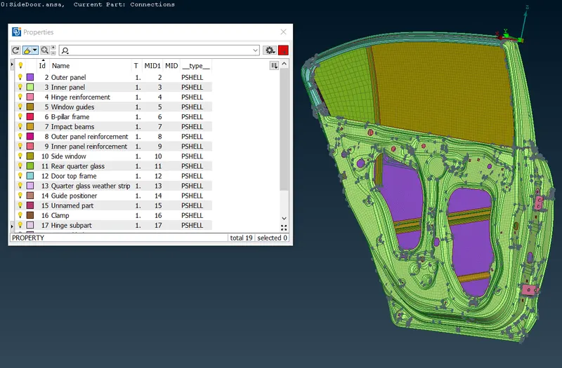
PID window
- Once you open the model understand the mechanism and necessary areas that need to rigidised or made connected.
Bolt connection
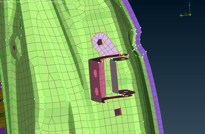
Hinge-Inner panel connection - Bolt connected
- Under the TOPO module select On COG below Points button to create a COG 3D point on any of the co-axial bolt holes as shown below.
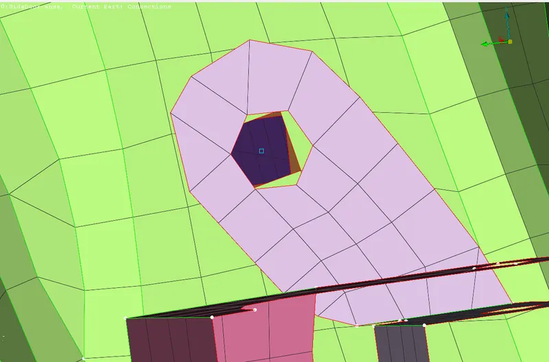
- Convert the 3D point into the bolt using Convert option in Assembly toolbar.
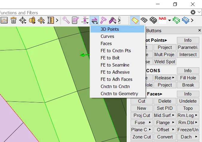
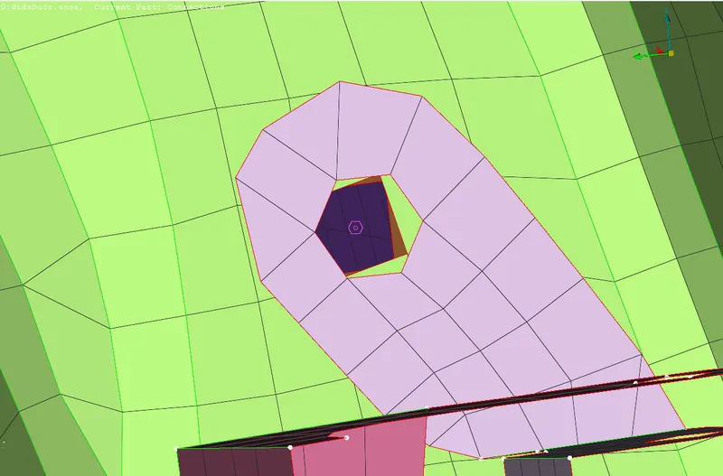
Bolt representation of a 3D point
- Open the Connection Manager to select the type of element and surfaces to be made connected.
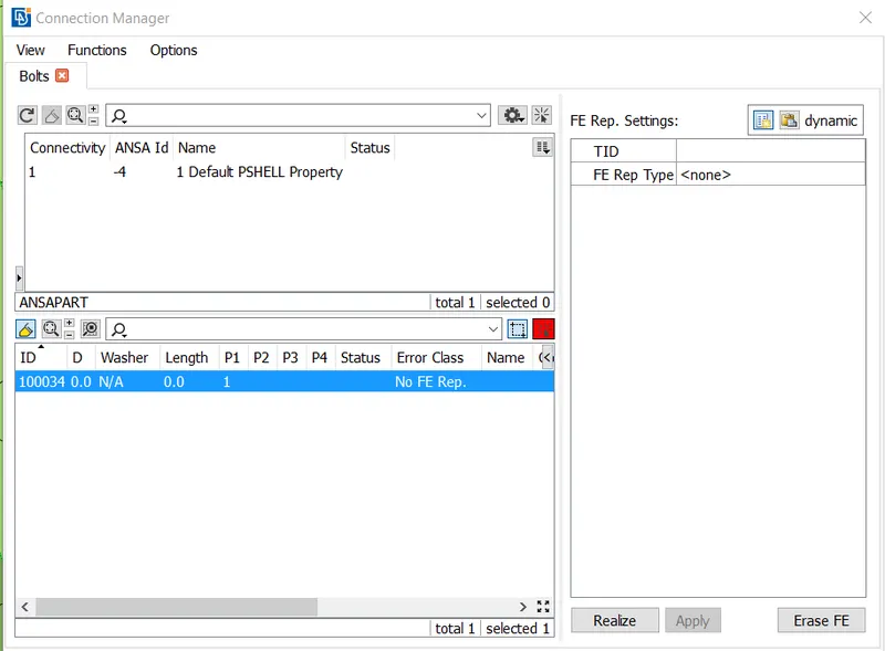
Connection Manager window
- Assign the values and P1, P2, P3, P4 surface to be made connections with.
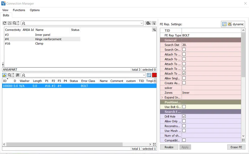
- Assign search distance as: 20, zone: Inner check the Body column to keep RB2 stem body(see below).
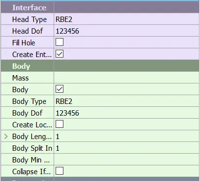
- Once you are done with assigning values then apply and realize the connection.
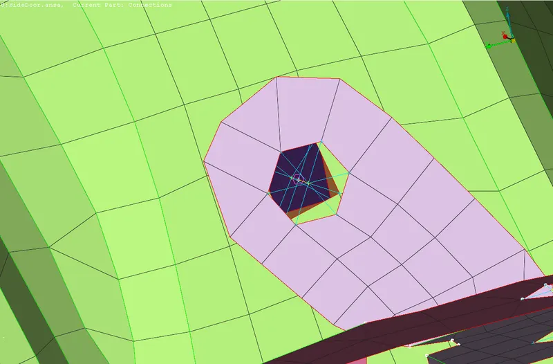
Bolt connection realized
- Hinge connection is also made using bolt connection the same way except that the rotational DOF along the axis of the bolt should be allowed.
- Do the same with all other bolt holes.
Open holes and slots connections
- We will use RBE2 many nodes option to rigidise those nodes. One by one we will select the open slots and holes any assign them many nodes RB2 rigid elements as shown below.
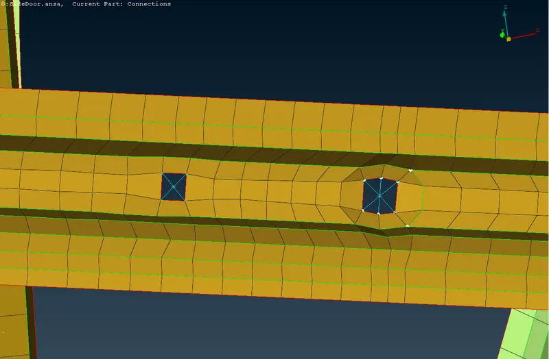
Spotweld connection
- Create a 3D point where the spotweld is to be made.
- Use the COG 3D point and convert that into a spot weld.
- For the spot weld, we use RB3-HEXA-RB3 and there in the connection manager use 'shift'+'?' key to select the weld PID.
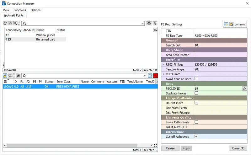
- Once you are done with assigning values then apply and realize the connection.
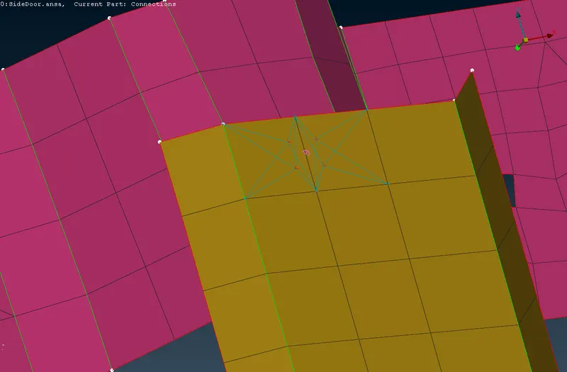
Spotweld connection realized
- Do the same with all other spotweld locations.
Seamweld connection
- Create a curve using Feat2Curve option where the seamweld is to be made.
- Convert the curve into a seamline using Convert -> Curves -> Seam line tool.
- Open the Connection Manager to select the type of element and surfaces to be made connected.
- Assign the values and P1, P2, P3, P4 surface to be made connections with.
- Select the FE Rep Type as OVERLAP-SHELL if the sheets to be welded are parallel to each other. If they are perpendicular, select Y-JOINT-SHELL.
- Give the search distance and select the Base Sheet.
- Type in the width of the weld such that the weld angle becomes 45 degrees.
- Select the type of root shells(Primary Row/Offset Row/Double Row) depending on the weld location.
- Assign the proper Weld PID.
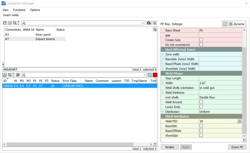
- Once you are done with assigning values then apply and realize the connection.
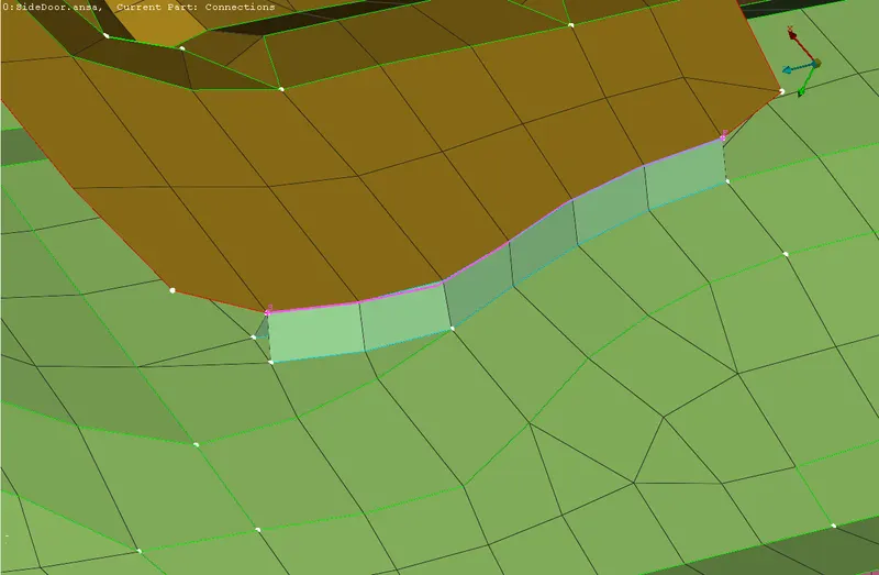
Seamweld connection realized
- Do the same with all other seamweld locations.
Weather Strip connection
- Hide the FE model except for the window glass and the quarter glass.
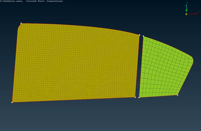
- Construct the curve all around the glass edge using Feat2Curve option. Select each edge of the glass one by one to do so.(as shown below)
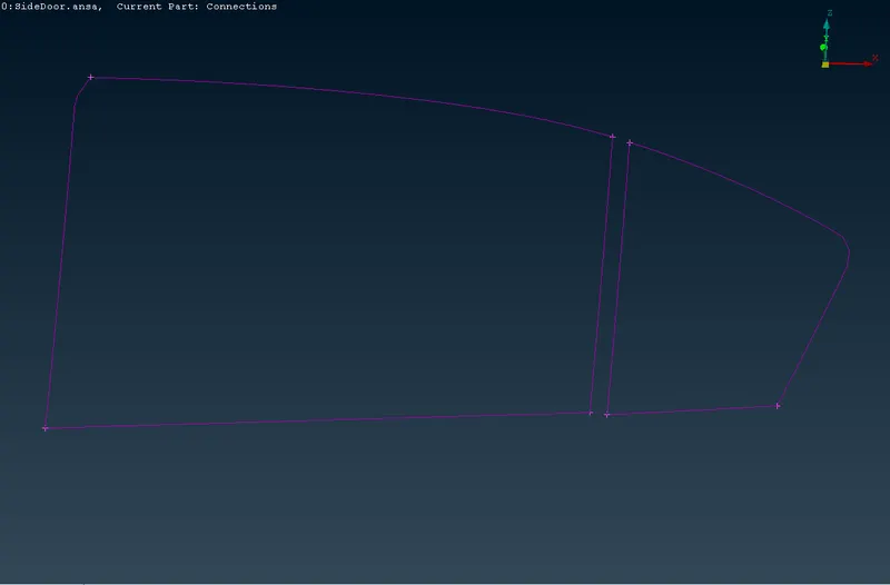
- Covert the curve to spot lines using Convert -> Curves -> Spot line tool. (one curve at a time)
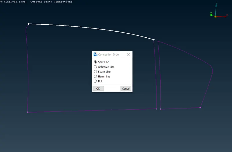
- Go to the Connection Manager to assign a connection. We use the RBE3-CBUSH-RBE3 element to assign connection. Also, set the PBUSH ID (doorlinks) to assign the stiffness values.
- Transform the base curve to 10 unit so as to apply connection on both sides of the window base.
- The stiffness value of the weather strip k will be given as per the solver requirements.
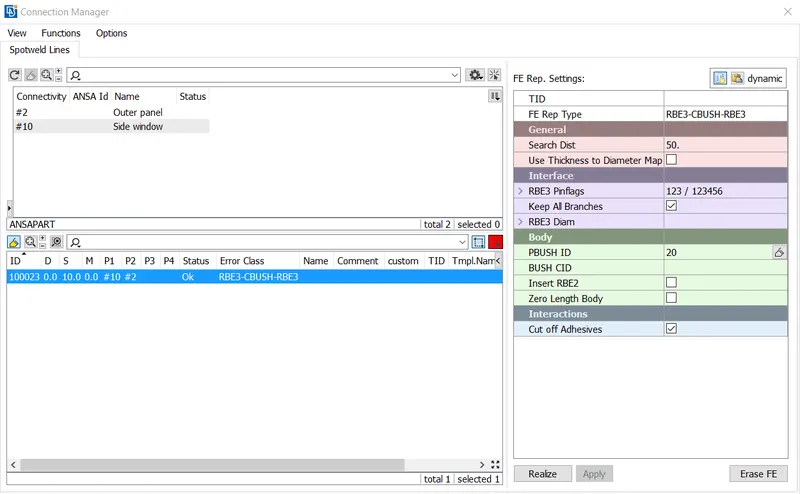
Connection Manager window
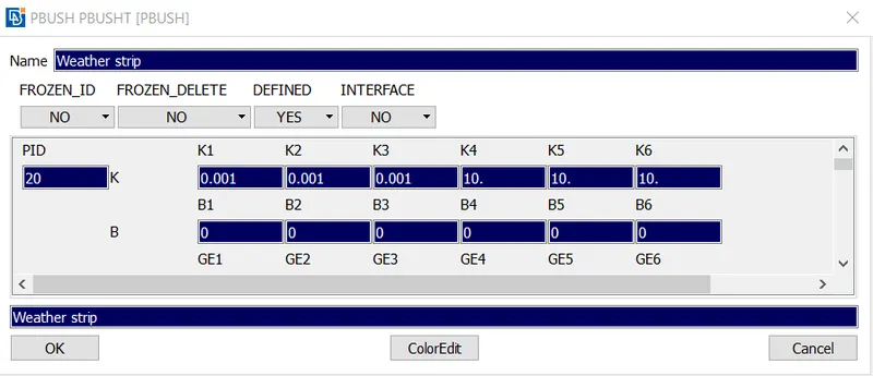
PBUSH property card
- Select the P1, P2 carefully then apply and realize.
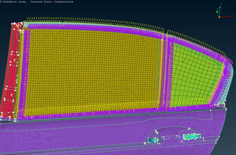
Weather strip connection realized
- Change all the CBUSH element orient as 'With Cord' and CID as 0 to change the orientation of the element from local to global coordinate system.
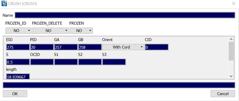
CBUSH element card
CONCLUSION :
After the completion of the challenge, it can be concluded that for any type of model, understanding of the mechanism is very important. As the mechanism will decide in analysis ways to make decisions regarding assigning connections. The connection procedure is moreover the same for any type of model but the requirement to assign the connection may differ from model to model with the requirement of the analysis. So for the NVH analysis, the weather seal was important to capture and is captured in a pretty good way with help of CBUSH element. Most of the areas are covered and are been rigidised as well as connected as per the requirements.