AIR STANDARD CYCLE - PLOTTING P-V DIAGRAM OF OTTO CYCLE USING MATLAB
AIM :
i) To code a program to plot the P-V diagram of Otto Cycle. ii) To output the thermal efficiency of the Otto Cycle from the program.
TOOLS REQUIRED :
MATLAB
THEORY :
Otto Cycle
The cycle of the Otto engine is called the Otto cycle. It is the one of most common thermodynamic cycles that can be found in automobile engines and describes the functioning of a typical spark ignition engine. In contrast to Carnot cycle, the Otto cycle does not execute isothermal processes, because these must be performed very slowly. In an ideal Otto cycle, the system executing the cycle undergoes a series of four internally reversible processes: two isentropic (reversible adiabatic) processes alternated with two isochoric processes.
P-V diagram of Otto cycle
Otto Cycle - Processes
Otto cycle undergoes a series of four reversible processes: two isentropic (reversible adiabatic) processes alternated with two isochoric processes.
- Isentropic Compression (compression stroke) – The gas (air-fuel mixture) is compressed isentropically from state 1 to state 2, as the piston moves from bottom dead center to top dead center. The surroundings do work on the gas, increasing its temperature and compressing it. On the other hand the entropy remains unchanged. This changes the volume and the ratio (V1/V2) is known as the compression ratio.
- Isochoric Compression (ignition phase) – In this phase (between state 2 and state 3) there is a constant volume heat transfer to the air from an external source while the piston is at rest at top dead center. This process is intended to represent the ignition of the fuel–air mixture injected into the chamber and the subsequent rapid burning. The pressure rises and the ratio (P3/P2) is known as the explosion ratio.
- Isentropic Expansion (power stroke) – The gas expands adiabatically from state 3 to state 4, as the piston moves from top dead center to bottom dead center. The gas does work on the piston and loses an amount of internal energy equal to the work that leaves the system. Again the entropy remains unchanged. The volume ratio (V4/V3) is known as the isentropic expansion ratio.
- Isochoric Expansion (exhaust stroke) – In this phase the cycle completes by a constant-volume process in which heat is rejected from the air while the piston is at bottom dead center. The working gas pressure drops instantaneously from state 4 to state 1. The exhaust valve opens at state 4. The exhaust stroke is directly after this expansion. As the piston moves from bottom dead center to top dead center with the exhaust valve opened, the gaseous mixture is vented to the atmosphere.
Engine Nomenclature
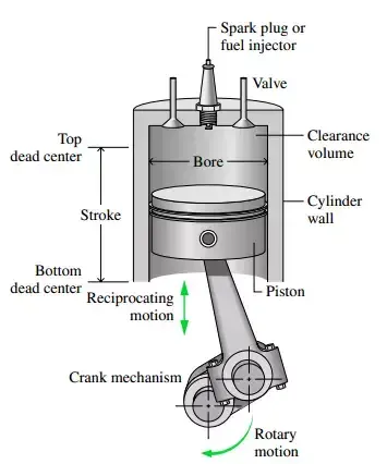
Engine cylinder components
- Bore (d) - In a piston engine, the bore (or cylinder bore) is the diameter of each cylinder.
- Stroke (L) - It is the distance travelled by the piston between TDC and BDC. The stroke along with bore determines the engine displacement.
- Connecting Rod - The connecting rod creates the link between the piston and crankshaft and thus transmits power. It converts the linear up and down movement of the piston into the circular motion of the crankshaft and is therefore subject to tension, compression, bending and buckling.
- Crank Angle (`theta`) - Crank angle refers to the position of an engine's crankshaft in relation to the piston as it travels inside the cylinder.
- Swept Volume (Vs) - It is the volume swept through by the piston in moving between TDC and BDC. It is also known as displacement volume.
`Vs = pi/4*d^2*L`
where, d = Bore
L = Stroke
- Clearance Volume (Vc) - It is the volume contained in the cylinder above the top of the piston, when the piston is at TDC.
`Vc = (Vs)/((CR)-1)`
where, Vs = Swept volume
CR = Compression Ratio
- Compression Ratio (CR) - In an engine, the compression ratio is the ratio between the volume of the cylinder and combustion chamber when the piston is at the BDC, and the volume of the combustion chamber when the piston is at the TDC.
`CR = (Vs + Vc)/(Vc)`
where, Vs = swept volume
Vc = clearance volume
- Total volume (V) - It is the sum of swept volume and clearance volume.
`V = Vs + Vc`
Thermodynamic Variables
The thermodynamic variables to be considered are :
- Pressure (P)
- Volume (V)
- Temperature (T)
Pressure, Volume and Temperature varies with crank angle according to the process it undergoes.
For an isentropic process, pressure and volume follows the relation,
`PV^gamma = const`
As the processes 1-2 and 3-4 are isentropic , volume(V) inside the cylinder varies with the crank angle according to the following relation,
`V/(Vc) = 1 + 1/2((CR)-1)[R+1-costheta-(R^2-(sintheta)^2)]`
where,
V = Total Volume
Vc = Clearance volume
CR = Compression ratio
R = (Connecting Rod length / Crank radius)
`theta` = Crank angle
Thermal Efficiency of Otto Cycle (`eta`)
Thermal efficiency of an Otto Cycle is given by the formula,
`eta = 1 -(1/((CR)^gamma-1))`
Assumed Data
- `gamma` = 1.4
- Temperature at state 3 (T3) = 2300 K
- Pressure at state 1 (P1) = 101325 Pa
- Temperature at state 1 (T1) = 500 K
- Bore (d) = 0.1m
- Stroke (L) = 0.1m
- Connecting rod length = 0.15m
- Compression ratio (CR) = 12
PROGRAM CODE :
Function to output the cylinder volume during isentropic process
function [V] = engine_kinematics(stroke,con_rod,comp_r,start_crank,end_crank,v_c)

c_r = stroke/2;
R = con_rod/c_r;

theta = linspace(start_crank,end_crank,end_crank-start_crank);

term1 = 0.5*(comp_r-1);
term2 = R+1-cosd(theta);
term3 = (R^2 - sind(theta).^2).^0.5;

V= (1 + term1*(term2-term3)).*v_c;
end
Program to plot P-V diagram of Otto Cycle
clear all
close all
clc

%Inputs
gamma = 1.4;
T3 = 2300

%state variables
P1 = 101325
T1 = 500

%Engine Parameters
bore = 0.1;
stroke = 0.1;
con_rod = 0.15;
comp_r = 12;

%Calculating swept volume and clearance volume
v_s = (pi/4)*bore^2*stroke
v_c = v_s/(comp_r-1)

V1 = v_s + v_c
V2 = v_c

%state variables at state 2
%P1*V1^gamma = P2*V2^gamma
P2 = P1*(comp_r^gamma)

%Ideal gas equation
%P1*V1/T1 = P2*V2/T2
T2 = P2*V2*T1/(P1*V1)

V_compression = engine_kinematics(stroke,con_rod,comp_r,180,360,v_c);
const_c1 = P1*(V1^gamma);
P_compression = const_c1./(V_compression.^gamma);


%state variables at state 3
V3 = V2

%Ideal gas equation
%P2*V2/T2 = P3*V3/T3
P3 = P2*T3/T2

V_expansion = engine_kinematics(stroke,con_rod,comp_r,0,180,v_c);
const_c2 = P3*(V3^gamma);
P_expansion = const_c2./(V_expansion.^gamma);


%state variables at state 4
V4 = V1

%P3*V3^gamma = P4*V4^gamma
P4 = P3*((V3/V4)^gamma)

hold on
plot(V1,P1,'*','color','r')
plot(V_compression,P_compression,'color','b')
plot(V2,P2,'*','color','r')
plot(V3,P3,'*','color','r')
plot([V2 V3],[P2 P3],'color','b')
plot(V_expansion,P_expansion,'color','b')
plot(V4,P4,'*','color','r')
plot([V4 V1],[P4 P1],'color','b')
xlabel('Volume')
ylabel('Pressure')

%Thermal Efficiency
Thermal_Efficiency = 1- (1/(comp_r^(gamma-1)))
Code Explanation
Function Definition
- A function named 'engine_kinematics()' is defined.
- The function takes stroke, connecting rod length, compression ratio, start crank angle, end crank angle, clearance volume as inputs.
- It initializes the crank angle to an array named 'theta'.
theta = linspace(start_crank,end_crank,end_crank-start_crank); - Then the function calculates the cylinder volume during an isentropic process and assign it to an array named 'V'
term1 = 0.5*(comp_r-1); term2 = R+1-cosd(theta); term3 = (R^2 - sind(theta).^2).^0.5; V= (1 + term1*(term2-term3)).*v_c; - The function returns the volume [V] array when it is called.
Program to plot P-V diagram
- First, the inputs and assumed data are initialized.
- Swept volume and Clearance volume are calculated.
v_s = (pi/4)*bore^2*stroke v_c = v_s/(comp_r-1) - State variables at points 1 and 2 are calculated using the isentropic relation and Ideal gas equation
- The function engine_kinematics() is called to return the cylinder volume into 'V_compression' and the corresponding pressure values (P_compression) are calculated.
V_compression = engine_kinematics(stroke,con_rod,comp_r,180,360,v_c); const_c1 = P1*(V1^gamma); P_compression = const_c1./(V_compression.^gamma); - State variables at points 3 and 4 are calculated using the isentropic relation and Ideal gas equation
- The function engine_kinematics() is again called to return the cylinder volume into 'V_expansion' and the corresponding pressure values (P_expansion) are calculated.
V_expansion = engine_kinematics(stroke,con_rod,comp_r,0,180,v_c); const_c2 = P3*(V3^gamma); P_expansion = const_c2./(V_expansion.^gamma); - The state points(1,2,3,4) and the process curves are plotted using the plot() command.
- At last, thermal efficiency is also calculated.
%Thermal Efficiency Thermal_Efficiency = 1- (1/(comp_r^(gamma-1)))
RESULTS :
- P-V diagram obtained from the program
- Thermal efficiency obtained from the program = 62.99%
ERROR ENCOUNTERED WHILE PROGRAMMING :
- Rectified the error by putting the '.' (dot operator) since 'V_compression' is an array.
CONCLUSION :
P-V diagram of Otto cycle is plotted and the thermal efficiency of the cycle have been obtained using MATLAB.