Project - 2 - Meshing on the suspension Assembly
AIM :
To mesh the Suspension subsystem assembly model with tetramesh elements according to the below-mentioned 2D and 3D quality criteria.
Quality Criteria for Surface Meshing of Tyre and Rim (Element type: Tria) :
|
S.No |
Quality Criteria |
Value |
|
1 |
Target/Average length |
6.5 |
|
2 |
Minimum Length |
5 |
|
3 |
Maximum Length |
10 |
|
4 |
Skewness |
45 |
Quality criteria for Surface Meshing of Non Uniform thickness components other than Tyre and Rim (Element type: Tria) :
|
S.No |
Quality Criteria |
Value |
|
1 |
Target/Average length |
4 |
|
2 |
Minimum Length |
2 |
|
3 |
Maximum Length |
6 |
|
4 |
Skewness |
45 |
Quality Criteria for Volume meshing of all Non Uniform thickness components (Element type: Tetra Elements):
|
S.No |
Quality Criteria |
Value |
|
1 |
Tet-collapse |
0.2 |
Quality criteria for Mid surfacing of Uniform thickness part which has thickness less than 5 mm (Element type: Mixed elements) :
|
S.No |
Quality Criteria |
Value |
|
1 |
Target/Average length |
4 |
|
2 |
Minimum Length |
2 |
|
3 |
Maximum Length |
6 |
|
4 |
Aspect |
3 |
|
5 |
Warpage |
15 |
|
6 |
Skewness |
45 |
|
7 |
Jacobian |
0.7 |
|
8 |
Minimum Quad Angle |
45 |
|
9 |
Maximum Quad Angle |
135 |
|
10 |
Minimum Tria Angle |
30 |
|
11 |
Maximum Tria Angle |
120 |
METHODOLOGY :
To mesh the suspension assembly, we need to follow these steps :
- Import geometry & Topological cleanup.
- Parts segregation under different property ID.
- Quality parameter and Mesh parameter setup as per the given requirements.
- Construction line adjustment and defeaturing.
- Mid-surface extraction if the components with a uniform thickness of less than 5 mm.
- Shell meshing and mesh correction.
- Volume definition and 3D mesh generation for non-uniform thickness components.
- Implementation of connections at required areas.
TOOLS REQUIRED :
- ANSA
INTRODUCTION :
Vehicle Suspension System
The suspension system must provide proper steering control and ride quality. Performing these functions is extremely important to maintain vehicle safety and customer satisfaction. For example, if the suspension system allows excessive vertical wheel oscillations, the driver may lose control of the steering when driving on an irregular road surface. This loss of steering control can result in a vehicle collision and personal injury. Excessive vertical wheel oscillations transfer undesirable vibrations from the wheel(s) to the passenger compartment, which causes customer dissatisfaction with the ride quality. The suspension system and frame must also position the wheels and tires properly to provide normal tire life and proper steering control. If the suspension system does not position each wheel and tire properly, wheel alignment angles are incorrect and usually cause excessive tire tread wear. Improper wheel and tire position can also cause the steering to pull to one side.
When the suspension system positions the wheels and tires properly, the steering should remain in the straight-ahead position if the car is driven straight ahead on a reasonably straight, smooth road surface. However, if the wheels and tires are not properly positioned, the steering can be erratic, and excessive steering effort is required to maintain the steering in the straight-ahead position. The steering system is also extremely important to maintain vehicle safety and reduce driver fatigue. For example, if a steering system component is suddenly disconnected, the driver may experience a complete loss of steering control, resulting in a vehicle collision and personal injury. Loose steering system components can cause erratic steering, which causes the driver to continually turn the steering wheel in either direction to try and keep the vehicle moving straight ahead. This condition results in premature driver fatigue.
The suspension system contains three major parts: a structure that supports the vehicle’s weight and determines suspension geometry, a spring that converts kinematic energy to potential energy or vice versa, and a shock absorber that is a mechanical device designed to dissipate kinetic energy.
An automotive suspension connects a vehicle’s wheels to its body while supporting the vehicle’s weight. It allows for the relative motion between the wheel and vehicle body; theoretically, a suspension system should reduce a wheel’s degree of freedom (DOF) from 6 to 2 on the rear axle and to 3 on the front axle even though the suspension system must support propulsion, steering, brakes, and their associated forces. The relative motions of the wheels are its vertical movement, rotational movement about the lateral axes, and rotational movement about the vertical axes due to the steering angle.
Car Suspension System
PROCEDURE :
Import geometry & Topological cleanup
- First of all, we need to import the CAD model into the ANSA interface. Then go for a geometry check and fix all the topological errors to proceed to the next step.
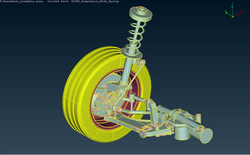
Suspension sub-assembly CAD model
- Then go for a geometry check and fix all the topological errors to proceed to the next step.
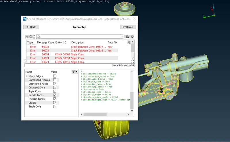
Geometry Checks Manager
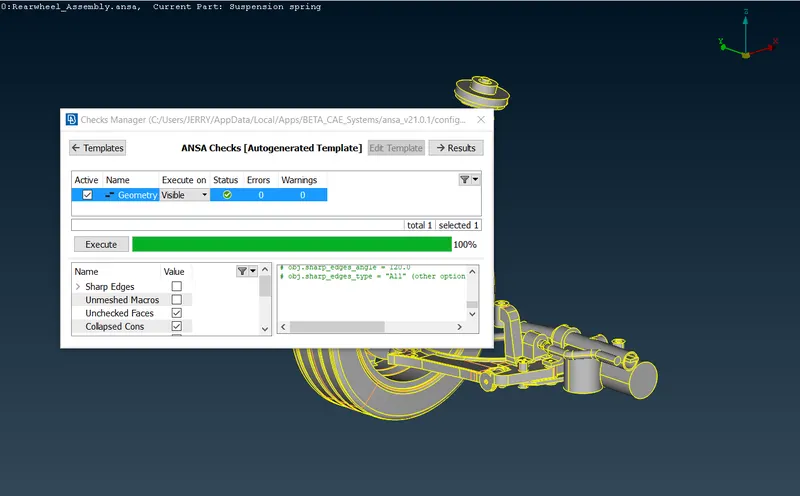
Geometrical errors cleared up
Parts segregation under different Property ID
- Once we have fixed all errors, we can segregate different parts under PID so as to proceed part by part which helps to expedite the process of pre-processing.
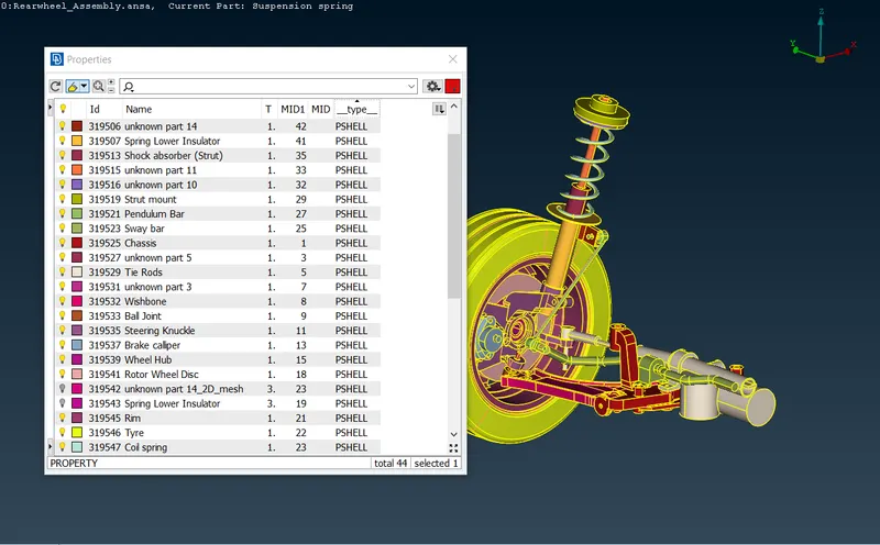
Properties window
Surface meshing of non-uniform thickness components
- The first step in meshing is to set the perimeter and macro length to the target element size using MESH module -> Perimeters -> Length tool.
- After that, mesh parameters have to be defined in Mesh Parameters option in Utilities menu. The main parameters include Target length, Min. Target length and Max. Target length. Also, the element type should be changed to Tria or Ortho Tria depending on the area of meshing.
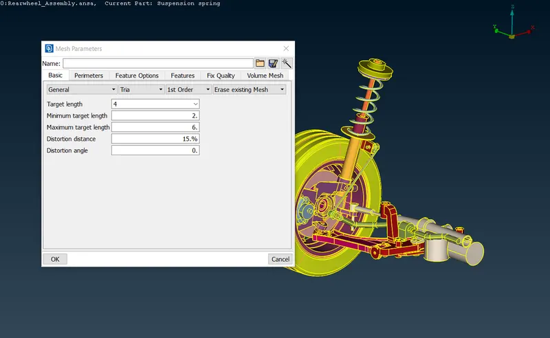
Mesh Parameters window
- Quality criteria are entered to check for element quality in Quality Criteria window from Utilities toolbar.
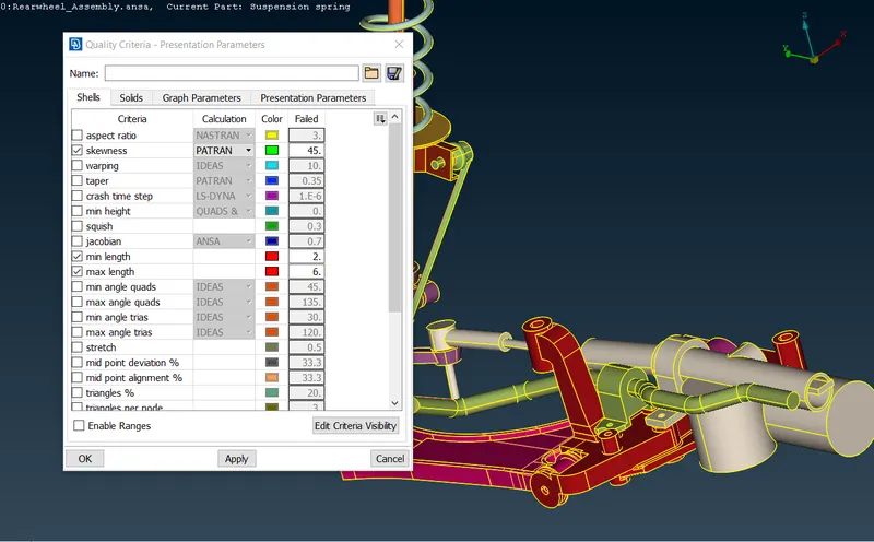
Quality criteria window
- The Best mesh algorithm gives a better result than other algorithms with better-optimized tria element adjustments. Also, we will use the ortho tria element for capturing the curved surface.
- The suspension system is meshed with Tria/Ortho Tria elements on the surface which is shown below.
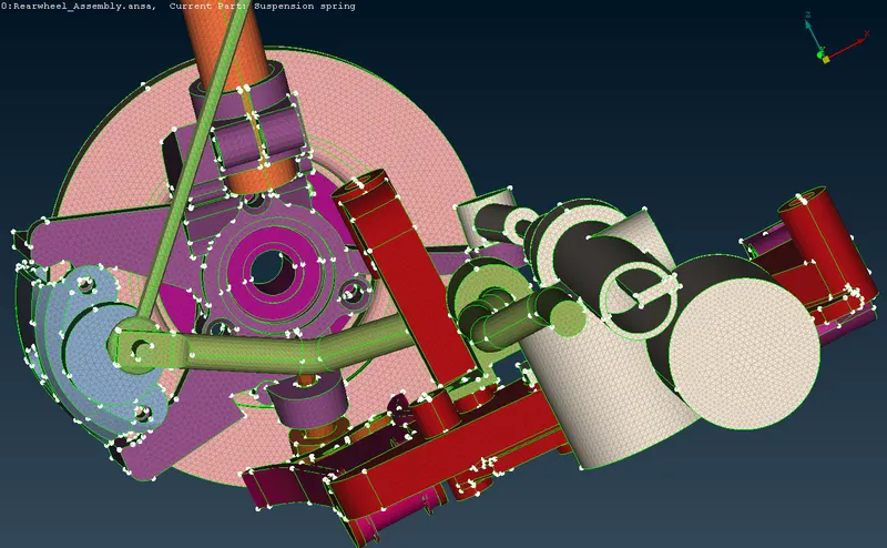
Shell mesh on the Suspension system
- Similarly, shell meshing is done on Tyre and Wheel Rim as per the quality criteria given for Tyre and Rim.
- Quality criteria for surface meshing of Tyre and Rim are entered in Quality Criteria window as shown below.
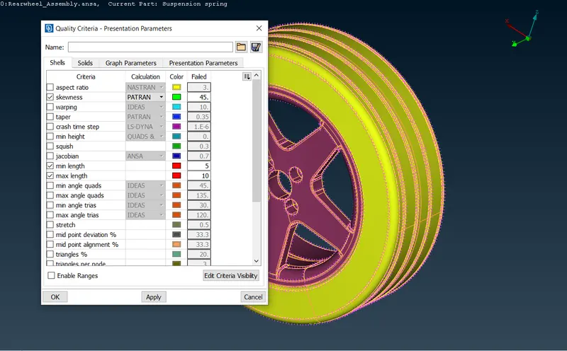
Quality criteria window
- Shell mesh on Tyre and Wheel Rim is shown below.
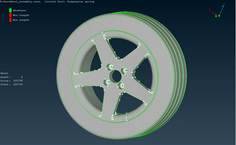
Shell mesh on Tyre and Wheel Rim
Mid-surface extraction for components with a uniform thickness of less than 5 mm
- There are only 2 components that have a thickness less than 5 mm(uniform thickness) and for those components, we will go with the mid surface extraction strategy.
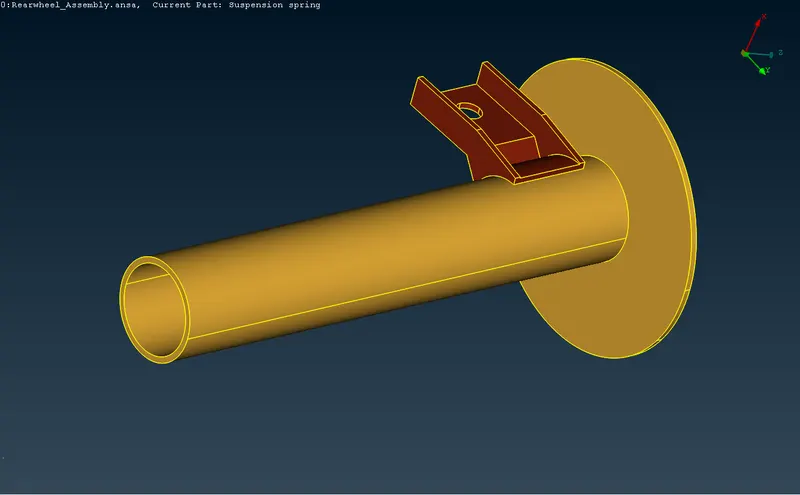
Components with uniform thickness less than 5mm
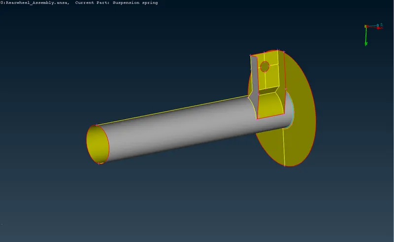
Mid-surface for components with uniform thickness less than 5mm
Volume definition and 3D Tetramesh generation for non-uniform thickness components
- The next step we need to do is define the volume and generate Tetra elements through the volume.
- But before defining them on the list, we need to make sure that the part is properly meshed and closed. Also, the part should not contain any overlapping surface. Define them one by one and set different PID type SOLID as shown below.
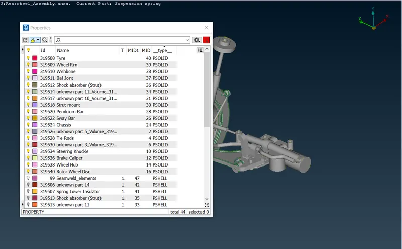
Properties window
- Tetra Rapid mesh algorithm is used to auto-generate the Tetra elements inside the volume. The generated tetramesh is shown below.
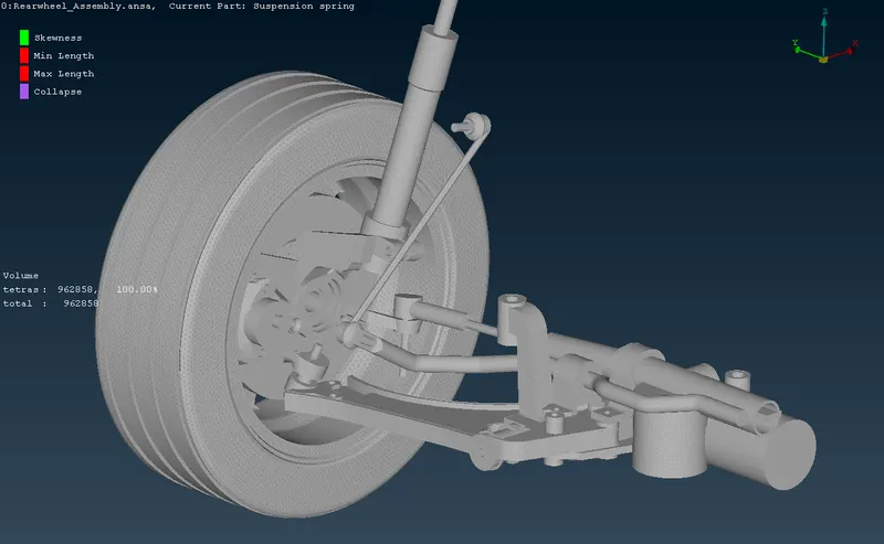
Tetramesh generated for Suspension Subsystem
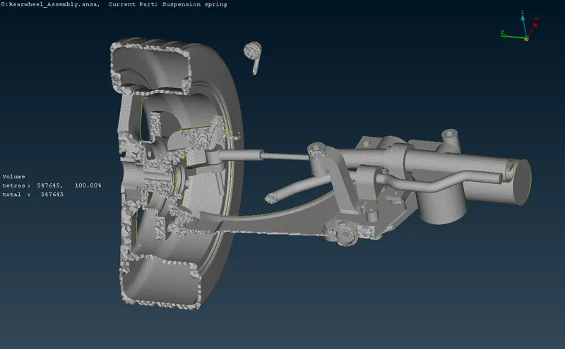
Sectional view of the generated tetramesh
Modelling the coil spring using 1D Bar elements
- Generate a middle curve for the spring using the Middle option in Curves button in TOPO module.
- Connect the curves into a single curve by using Connect -> Multi option in Curves button in TOPO module.
- Create a COG point for the curve to define the orientation of the bar element.
- Select the CBAR option in ELEMENTs button in NASTRAN deck module.
- In the CBAR element window, change the selection type to Curve(Box).
- Select the curve and select the orientation node.
- Specify the element length and define a PID for the CBAR elements by creating a new PID.
- Define cross-sectional area of the bar element by entering the radius of the coil spring.
- The coil spring bar elements are created in this manner and is shown below.
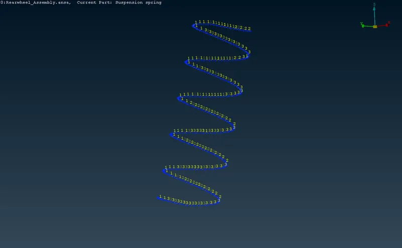
CBAR element representation of Coil Spring
Implementation of connections at required areas
- There are specific areas that need connections representing bolt, weld, and rigid connections.
- Bolt connections are made at the required locations using Bolt tool in Assembly toolbar.
- The realized bolt connections are shown below.
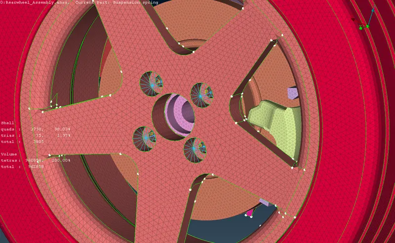
Bolt connection between Wheel Rim, Wheel Hub and Rotor Wheel Disc
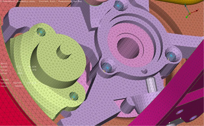
Bolt connection between Wheel Hub and Steering Knuckle
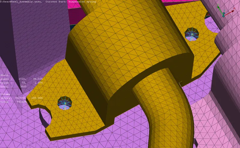
Bolt connection between Sway Bar and Chassis
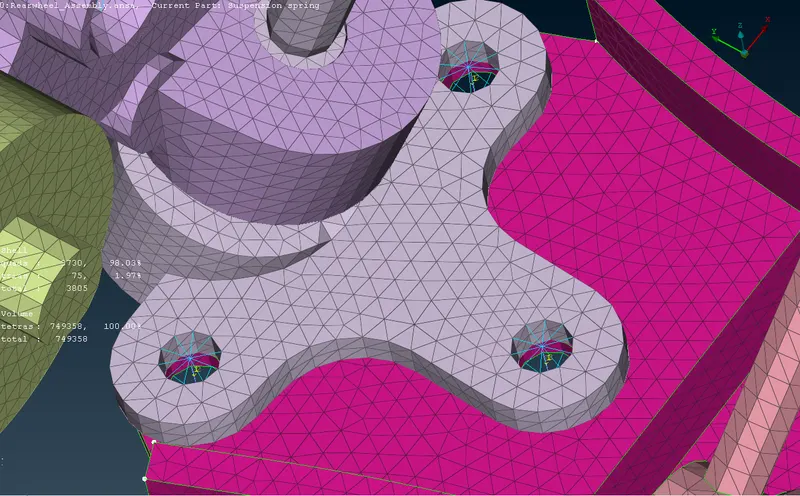
Bolt connection between Ball joint and Wishbone
- Seamweld connection is made at one location using OVERLAP SHELL method in Connection Manager tool in Assembly toolbar.
- The realized seamweld is shown below.
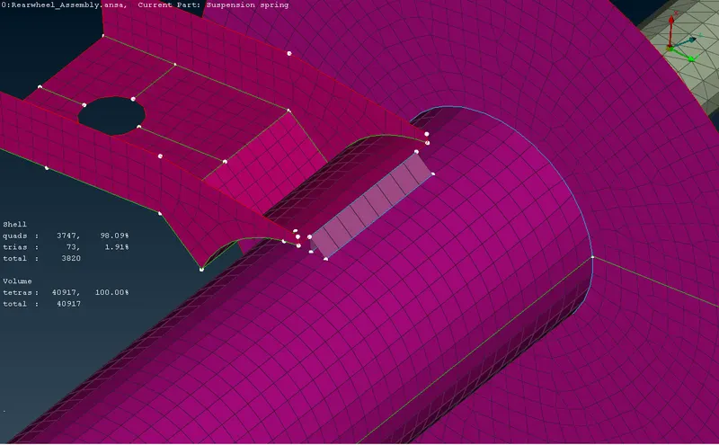
Seamweld connection
RESULT :
- So finally we have completed the meshing process and connection realization.
- The final meshed model model with connections is shown below.
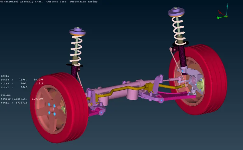
Suspension System Sub-assembly
CONCLUSION :
All the components of a suspension system are captured quite decently with solid elements(Tetra) and shell element as per the quality requirements. There are a total of 1925716 tetra elements under the volume meshing (3D) free from any Tetra collapse. The curved areas were mainly captured with the ortho Tria element during shell meshing on solid objects which helped to capture the feature correctly. The meshed final model has a smooth surface free from any dip or kinks and can be considered for further processing.
LEARNING OUTCOMES :
- Geometry check and cleanup.
- 1D, 2D(shell), and 3D(solid) meshing.
- Implementation of connections.
- Car suspension system components and their purpose.