Week-7 Challenge: DC Motor Control
1)Aim:
To explain the Speed control of a DC motor using the BJT H-bridge model.
Model:
Explanation:
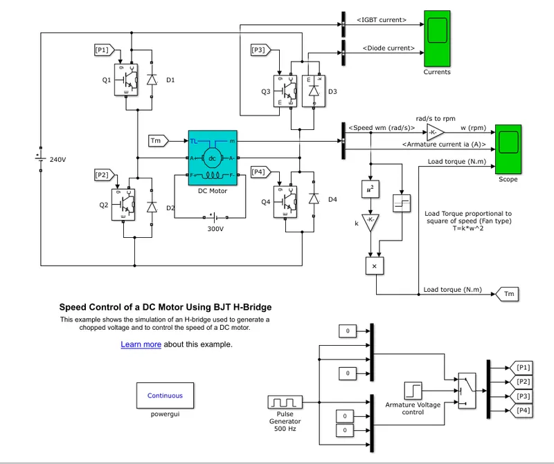
The Bipolar Junction Transistor (BJT) when used for power switching applications, operates as an IGBT. When it is conducting (BJT operating in the saturated region), a forward voltage Vf is developed between collector and emitter (in the range of 1 V). Therefore, the IGBT block can be used to model the BJT device.
The IGBT block does not simulate the gate current controlling the BJT or IGBT. The switch is controlled by a Simulink® signal (1/0). The DC motor uses the preset model (5 HP 24V 1750 rpm). It simulates a fan type load (where Load torque is proportional to the square of speed). The armature means voltage can be varied from 0 to 240 V when the duty cycle (specified in the Pulse Generator block) is varied from 0 to 100%.
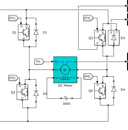
From the above figure, the H-bridge consists of four BJT/Diode pairs (BJT simulated by IGBT models). Two transistors are switched simultaneously: Q1 and Q4 or Q2 and Q3. When Q1 and Q4 are fired, a positive voltage is applied to the motor and diodes D2-D3 operate as free-wheeling diodes when Q1 and Q4 are switched off. When Q2 and Q3 are fired, a negative voltage is applied to the motor and diodes D1-D4 operate as free-wheeling diodes when Q2 and Q3 are switched off.
Result:
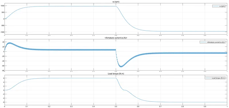
The motor starts in the positive direction with a duty cycle of 75% (mean DC voltage of 180V). At t= 0.5 sec., the armature voltage is suddenly reversed and the motor runs in the negative direction.
b)Aim:
To explain the armature current shoot up in the Speed control of a DC motor using the BJT H-bridge model.
Explanation:
`I_a= (V-E_b)/R_a`
In the case of DC Motor, at the time of starting Back Emf is zero so armature current depends on only the voltage and armature resistance where the armature is low so armature current is High. Later as the back emf increases the armature current decreases.
c)Aim:
To compare the Four-Quadrant Chopper DC Drive (DC7) block with the H-bridge model and explain it.
Model:
Explanation:
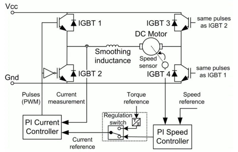
The Four-Quadrant Chopper DC Drive (DC7) block represents a four-quadrant, DC-supplied, chopper (or DC-DC PWM converter) drive for DC motors. This drive features closed-loop speed control with a four-quadrant operation. The speed control loop outputs the reference armature current of the machine. Using a PI current controller, the chopper duty cycle corresponding to the commanded armature current is derived. This duty cycle is then compared with a sawtooth carrier signal to obtain the required PWM signals for the chopper.
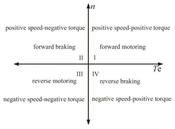
The main advantage of this drive, compared with other DC drives, is that it can operate in all four quadrants (forward motoring, reverse regeneration, reverse motoring, and forward regeneration). In addition, due to the use of high switching frequency DC-DC converters, a lower armature current ripple (compared with thyristor-based DC drives) is obtained. However, four switching devices are required, which increases the complexity of the drive system.
The Four-Quadrant Chopper DC Drive block uses these blocks from the Electric Drives/Fundamental Drive Blocks library:
-
Speed Controller (DC)
-
Regulation Switch
-
Current Controller (DC)
-
Chopper
Comparison:
| Four Quadrant DC Chopper | H-Model |
| Four modes of operation are possible | Two modes of operation are possible |
| Regenerative Braking is possible | Regenerative Braking is not possible |
| Armature Current Ripple is less | Armature Current Ripple is high |
| More Complex | less Complex |
| PI regulator is used | PI regulator is not used |
| High Efficiency Compared To H-Model | less Efficiency Compared Four quadrant DC Chopper |
2)Aim:
To develop the Two quadrant chopper model using Simulink and explain it.
Explanation:
A chopper is a static device that converts fixed DC input voltage to a variable DC output voltage. It is basically a high-speed ON/OFF semiconductor switch.
Two Quadrant Chopper:
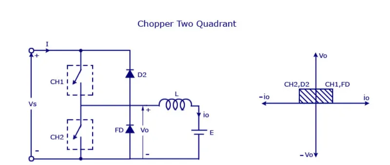
The two Quadrant Chopper is also known as Type C Chopper. When CH1 is ON the current flow from source to load.The inductor Stores the energy.When the CH1 is turned off the freewheeling diode conducts and output voltage is equal is Supply voltage.The direction of current is reversed and flow towards the source.The current will negative when CH2 is On and completes through path diode D2.
Model:
Explanation:
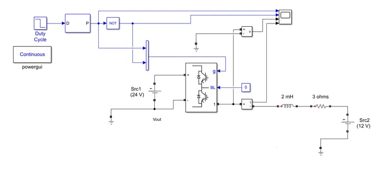
The Two quadrant DC_DC Converter block is used to implement the model. The PWM generator Block is used with the switching frequency of 1e3 and fed with the duty cycle of 75%. The two MOSFET should not be ON simultaneously, it would lead to a direct short circuit of the supply lines. Therefore NOT block is used.
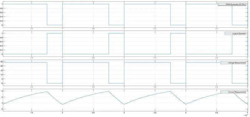
The average voltage is positive an average current will be negative or positive.For regenrative Braking and motoring these types chopper is used.
3)Aim:
To explain the operation of Brushless DC Motor.
Explanation:
A BLDC motor accomplishes commutation electronically using rotor position feedback to determine when to switch the current. The stator windings work in conjunction with permanent magnets on the rotor to generate a nearly uniform flux density in the air gap. This permits the stator coils to be driven by a constant DC voltage (hence the name brushless DC), which simply switches from one stator coil to the next to generate an AC voltage waveform with a trapezoidal shape.
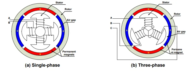
The above diagram shows the Brushless Dc Motor with a single-phase and three-phase connection respectively.
Operation:
BLDC motor works on the principle similar to that of a conventional DC motor, i.e., the Lorentz force law which states that whenever a current-carrying conductor placed in a magnetic field it experiences a force. As a consequence of the reaction force, the magnet will experience an equal and opposite force. In the case BLDC motor, the current-carrying conductor is stationary while the permanent magnet moves. When the stator coils are electrically switched by a supply source, it becomes an electromagnet and starts producing the uniform field in the air gap. Though the source of supply is DC, switching makes to generates an AC voltage waveform with a trapezoidal shape. Due to the force of interaction between the electromagnet stator and the permanent magnet rotor, the rotor continues to rotate.