Week -2
Aim:
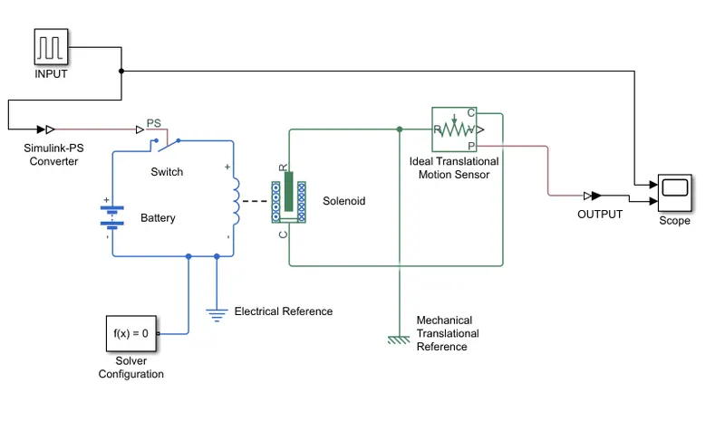
To construct a Simulink model of a Doorbell using solenoid block
Block Required:
- Pulse Generator (Input)
- Simulink - PS Converter
- Battery
- Switch
- Solver Configuration
- Electrical Reference
- Solenoid
- Ideal Translational Motion Sensor
- PS- Simulink Converter
- Scope
- Mechanical Translational Reference
Model:
Result & Explanation:
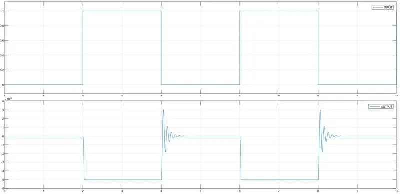
To create the switch closed for 2 sec and then release, the following configuration is made in the pulse generator.
Amplitude: 1
Period: 4 sec
Pulse width: 50% of the period
Phase delay: 2 sec
The Voltage of the Battery is the same as the solenoid rated voltage. In the solenoid block, Motion direction under excitation is Port R moves away from C
The position of the solenoid is measured via an ideal translational motion sensor connected to the circuits.
The initial position of the ideal translational motion sensor is 0 mm. The Output of ideal translational motion sensor connected to the scope via Ps -Simulink Converter.
The Pulse generator is connected to the switch and scope to visualize the behavior.
Aim:
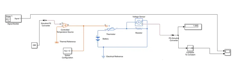
To sense the temperature of a heater and turn on the fan as per the given condition.
Condition:
- 20 °C from 0 to 10 seconds,
- 27 °C from 10 to 30 seconds,
- 23 °C from 30 to 50 seconds.
- Turn on the Fan when the temperature greater than 25°C
Blocks Required:
- Signal Builder
- Controlled Temperature Source
- Solver Configuration
- Thermal Reference
- Battery
- Thermistor
- Resistor
- Voltage Sensor
- Compare Constant
- Scope
- Electrical Reference
- Simulink PS Converter
- PS Simulink COnverter.
Model:
Output & Explanation:
When the temperature is 20 °C (293 K) the output voltage measured through the voltage sensor is 0.9015 V.
When the temperature is 27 °C (300 K) the output voltage measured through the voltage sensor is 1.163 V.
When the temperature is 23 °C (296 K) the output voltage measured through the voltage sensor is 1.008 V.
When the temperature is 25 °C (298 K) the output voltage measured through the voltage sensor is 1.08 V
The output of the voltage sensor is fed through PS -Simulink converter and compare to constant block is used to compare the output voltage greater than 1.08 V or not.
From the above inference, we can conclude that when the voltage is greater than 1.08 V we can turn on the Fan.
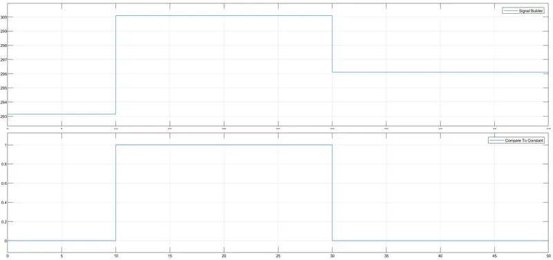
In the above Figure, for (0 - 10) sec the temperature is 293 k so the fan is off state indicates by the value zero
and for (10 - 30) sec the temperature is 300 K greater than 298 K so the fan should be turned on which is indicated by value one in the figure.