Project-1: Powertrain for aircraft in runways
1)Aim:
To list out the total weight of various types of aircraft.
Explanation:
Aircraft Gross Weight:
The aircraft gross weight (also known as the all-up weight and abbreviated AUW) is the total aircraft weight at any moment during the flight or ground operation. An aircraft's gross weight will decrease during a flight due to fuel and oil consumption. An aircraft's gross weight may also vary during a flight due to payload dropping or in-flight refuelling. At the moment of releasing its brakes, the gross weight of an aircraft is equal to its takeoff weight. During the flight, an aircraft's gross weight is referred to as the en-route weight or in-flight weight.
Design Weight limits:
An aircraft's gross weight is limited by several weight restrictions in order to avoid overloading its structure or to avoid unacceptable performance or handling qualities while in operation. Aircraft gross weight limits are established during an aircraft's design and certification period and are laid down in the aircraft's type certificate and manufacturer specification documents. The absolute maximum weight capabilities of a given aircraft are referred to as the structural weight limits. The structural weight limits are based on aircraft maximum structural capability and define the envelope for the CG charts (both maximum weight and CG limits).
Maximum Design taxi Weight(MDTW):
The maximum design taxi weight (also known as the maximum design ramp weight (MDRW)) is the maximum weight certificated for aircraft maneuvering on the ground (taxiing or towing) as limited by aircraft strength and airworthiness requirements.
Maximum Design Takeoff Weight(MDTOW):
Is the maximum certificated design weight when the brakes are released for takeoff and is the greatest weight for which compliance with the relevant structural and engineering requirements has been demonstrated by the manufacturer.
Maximum Design Landing Weight(MDLW):
The maximum certificated design weight at which the aircraft meets the appropriate landing certification requirements. It generally depends on the landing gear strength or the landing impact loads on certain parts of the wing structure. The MDLW must not exceed the MDTOW. The maximum landing weight is typically designed for 10 feet per second (600 feet per minute) sink rate at touch down with no structural damage.
Maximum Design Zero-Fuel Weight(MDZFW):
The maximum certificated design weight of the aircraft less all usable fuel and other specified usable agents (engine injection fluid, and other consumable propulsion agents). It is the maximum weight permitted before usable fuel and other specified usable fluids are loaded in specified sections of the airplane. The MDZFW is limited by strength and airworthiness requirements. At this weight, the subsequent addition of fuel will not result in the aircraft design strength being exceeded. The weight difference between the MDTOW and the MDZFW may be utilized only for the addition of fuel.
Maximum flight Weight(MFW):
Minimum certificated weight for flight as limited by aircraft strength and airworthiness requirements.
Authorized Weight limits:
Aircraft authorized gross weight limits (also referred to as certified weight limits) are laid down in the aircraft flight manuals (AFM) and/or associated certificates of airworthiness (C of A). The authorized or permitted limits may be equal to or lower than the structural design weight limits. The authorized weight limits that can legally be used by an operator or airline are those listed in the AFM and the weight and balance manual.
Maximum taxi weight(MTW):
The maximum taxi weight (MTW) is the maximum weight authorized for maneuvering (taxiing or towing) an aircraft on the ground as limited by aircraft strength and airworthiness requirements. It includes the weight of the taxi and run-up fuel for the engines and the APU.It is greater than the maximum takeoff weight due to the fuel that will be burned during the taxi and runup operations.The difference between the maximum taxi/ramp weight and the maximum take-off weight (maximum taxi fuel allowance) depends on the size of the aircraft, the number of engines, APU operation, and engines/APU fuel consumption, and is typically assumed for 10 to 15 minutes allowance of taxi and run-up operations.
Maximum takeoff weight(MT0W):
The maximum takeoff weight (also known as the maximum brake-release weight) is the maximum weight authorized at brake release for takeoff, or at the start of the takeoff roll. The maximum takeoff weight is always less than the maximum taxi/ramp weight to allow for fuel burned during taxi by the engines and the APU.In operation, the maximum weight for takeoff may be limited to values less than the maximum takeoff weight due to aircraft performance, environmental conditions, airfield characteristics (takeoff field length, altitude), maximum tire speed and brake energy, obstacle clearances, and/or en route and landing weight requirements.
Maximum landing weight(MLW):
The maximum weight authorized for the normal landing of an aircraft. The MLW must not exceed the MTOW. The operation landing weight may be limited to a weight lower than the Maximum Landing Weight by the most restrictive of the following requirements:
- Aircraft performance requirements for a given altitude and temperature depend upon thelanding field length requirements, approach and landing climb requirements
- Noise requirements
If the flight has been of short duration, fuel may have to be jettisoned to reduce the landing weight. Overweight landings require a structural inspection or evaluation of the touch-down loads before the next aircraft operation.
Maximum zero-fuel weight(MZFW):
The maximum permissible weight of the aircraft less all usable fuel and other specified usable agents (engine injection fluid, and other consumable propulsion agents). It is the maximum weight permitted before usable fuel and other specified usable fluids are loaded in specified sections of the airplane.
Operating Empty Weight:
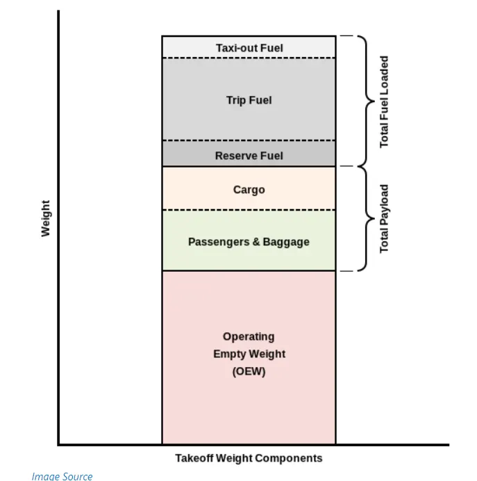
It is the basic weight of an aircraft including the crew, all fluids necessary for operation such as engine oil, engine coolant, water, unusable fuel and all operator items and equipment required for flight but excluding usable fuel and the payload.
Payload:
It is the carrying capacity of an aircraft. It includes cargo, people, extra fuel. In the case of a commercial airliner, it may refer only to revenue-generating cargo or paying passengers.
2)Aim:
To explain the difference between ground speed and airspeed.
Explanation:
Ground Speed
For a reference point picked on the ground, the aircraft moves relative to the reference point at the ground speed. Ground speed is also a vector quantity so a comparison of the ground speed to the wind speed.
Airspeed
The important quantity in the generation of lift is the relative velocity between the object and the air, which is called the airspeed. Airspeed cannot be directly measured from a ground position but must be computed from the ground speed and the wind speed. Airspeed is the vector difference between the ground speed and the wind speed.
Airspeed = Ground Speed - Wind Speed
On a perfectly still day, the airspeed is equal to the ground speed. But if the wind is blowing in the same direction that the aircraft is moving, the airspeed will be less than the ground speed.
While traveling by car the speed is measured relative to the ground or nearby object for eg tree. Similarly, The aircraft in no wind condition aircraft speed would be measured relative to the ground or the objects as we would travel by car. In this case, the distance traveled per unit time would also be the same however when the wind appears, air moves therefore even though you will flying at the same speed your travel distance relative to the ground will be different you will travel further or in other words, speed relative to the ground will differ from the speed relative to the air. In aviation, ground speed is expressed as GS. There are many airspeed but the speed which corresponds to the movement relative to the air is called true airspeed or TAS. In the case of wind blowing from the tail or also known as tailwind ground speed will be higher than true airspeed. If the wind blows from the opposite direction or having a headwind the airspeed higher than ground speed.
Tailwind condition:Gs = TAS+ wind component.
Headwind condition: GS=TAS-wind component.
3)Aim:
To explain the Aircraft engine power not recommended to move aircraft on the ground at Airport.
Explanation:
Airplanes use their jet engines for taxing just like for flying. And they have no additional engines to power the wheels. The wheels of an airplane rotate freely as the plane depends on the thrust from its jet engines to propel it forwards or backwards. However despite the engines being capable of powering the airplane's 'pushback' from the terminal/gate, they are rarely used for this purpose. 'Tug vehicles' are generally used to pushback the plane away from the terminal prior to take-off. These are specialized vehicles with high torque and heavy mass. The reason for the use of tugs is that the alternative (i.e., pushback using the jet-engine's thrust-reverser) is a highly fuel-consuming and noisy process. It is also potentially hazardous for personnel working near the plane. Once the plane is tugged away to a safe distance from the terminal, the plane begins using its own engine power for the rest of the taxing process.
4)Aim:
To explain how aircraft is pushed to the runway when it's ready to take off.
Explanation:
In aviation, pushback is an airport procedure during which an aircraft is pushed backward away from its parking position, usually at an airport gate by an external power. Pushbacks are carried out by special, low-profile vehicles called pushback tractors or tugs. Although many aircraft are capable of moving themselves backward on the ground using reverse thrust, the resulting jet blast might cause damage to the terminal building or equipment. Engines close to the ground may also blow sand and debris forward and then suck them into the engine, causing damage to the engine. A pushback is therefore the preferred method to move the aircraft away from the gate.
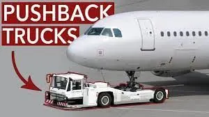
Conventional tugs use a tow bar to connect the tug to the nose landing gear of the aircraft. The tow bar is fixed laterally at the nose landing gear but may move slightly vertically for height adjustment. At the end that attaches to the tug, the tow bar may pivot freely laterally and vertically. In this manner, the tow bar acts as a large lever to rotate the nose landing gear. Each aircraft type has a unique tow fitting so the towbar also acts as an adapter between the standard-sized tow pin on the tug and the type-specific fitting on the aircraft's landing gear. The tow bar must be long enough to place the tug far away enough to avoid hitting the aircraft and to provide sufficient leverage to facilitate turns.
Towbarless (TBL) tractors do not use a towbar; they scoop up the nose landing gear and lift it off the ground. This avoids the time penalty of connecting/disconnecting a towbar and entirely removes the cost/complexity of maintaining towbars on the ramp. The tug itself does not need to be particularly massive - the aircraft's nosewheel weight provides the necessary downward force. Lastly, a TBL tug is much shorter (compared to a tug+towbar system) and has one only a single pivot point instead of one at either end of the towbar, so it has much simpler and precise control of the aircraft. This is very useful in general aviation settings with a wider variety of aircraft in more confined spaces than their airline counterparts.
The Lahav Division of Israel Aerospace Industries has developed a semi-robotic towbarless tractor it calls Taxibot that can tow an aircraft from the terminal gate to the take-off point (taxi-out phase) and return it to the gate after landing (taxi-in phase). The Taxibot eliminates the use of airplane engines during taxi-in and until immediately prior to take-off during taxi-out potentially saving airlines billions of dollars in fuel that is used. The Taxibot is controlled by the pilot from the cockpit using the regular pilot controls
5)Aim:
To explain the take-off power, tyre design, rolling resistance, tyre pressure and brake forces when landing.
Explanation:
Take-OFF Power:
The amount of power that an engine is allowed to produce for a limited period of time for takeoff. The use of takeoff power is usually limited to 5 min for reciprocating engines and up to 2½ min for gas turbine engines. This may not always be the case. Specifically, with respect to reciprocating engines, it is the brake horsepower developed under standard, sealevel conditions and under the maximum conditions of the crankshaft rotational speed and the engine manifold pressure approved for the normal takeoff. It is limited in continuous use to the period of time shown in the approved engine specifications. With respect to gas turbine engines, it is the thrust developed under static conditions at a specified altitude and atmospheric conditions of the rotor shaft rotational speed and gas temperature approved for the normal takeoff. It is limited in continuous use to the period of time shown in the approved engine specifications.
Tyre Design:
| Types | Uses |
| Type III tire | common general aviation tires |
| Type VII tires | high-performance found on jet aircraft |
| Type VIII tires | high-performance jet aircraft |
Tyre Construction:
Bead:
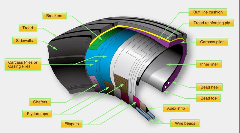
The tire bead is an important part of an aircraft tire. It anchors the tire carcass and provides a dimensioned, firm mounting surface for the tire on the wheel rim. Tire beads are strong. They are typically made from high-strength carbon steel wire bundles encased in rubber. One, two, or three bead bundles may be found on each side of the tire depending on its size and the load it is designed to handle. Radial tires have a single bead bundle on each side of the tire. The bead transfers the impact loads and deflection forces to the wheel rim. The bead toe is closest to the tire centerline and the bead heel fit against the flange of the wheel rim. An apex strip is an additional rubber formed around the bead to give a contour for anchoring the ply turn-ups. Layers of fabric and rubber called flippers are placed around the beads to insulate the carcass from the beads and improve tire durability. Chafers are also used in this area. Chafer strips made of fabric or rubber are laid over the outer carcass plies after the plies are wrapped around the beads. The chafers protect the carcass from damage during mounting and demounting of the tire. They also help reduce the effects of wear and chafing between the wheel rim and the tire bead especially during dynamic operations.
Carcass Plies:
Carcass plies, or casing plies as they are sometimes called, are used to form the tire. Each ply consists of fabric usually, nylon, sandwiched between two layers of rubber. The plies are applied in layers to give the tire strength and form the carcass body of the tire. The ends of each ply are anchored by wrapping them around the bead on both sides of the tire to form the ply turn-ups. As mentioned, the angle of the fiber in the ply is manipulated to create a bias tire or radial tire as desired. Typically, radial tires require fewer plies than bias tires. Once the plies are in place, bias tires and radial tires each have their own type of protective layers on top of the plies but under the tread of the running surface of the tire. On bias tires, these single or multiple layers of nylon and rubbers are called tread reinforcing plies. On radial tires, an undertread and a protector ply do the same job. These additional plies stabilize and strengthen the crown area of the tire. They reduce tread distortion under load and increase stability of the tire at high speeds. The reinforcing plies and protector plies also help resist puncture and cutting while protecting the carcass body of the tire.
Rolling resistance:
The friction between the aircraft and the runway will be proportional to the normal force exerted by the aircraft on the runway.
The normal force will be the difference between the Weight of the aircraft and the Lift, the friction coefficient will be typically of a magnitude of 0.02 for a standard tarmac runway.
Tyre Pressure:
Aircraft tires generally operate at high pressures, up to 200 psi for airliners, and even higher for business jets.The main landing gear on the Concorde was typically inflated to 232 psi (16.0 bar), whilst its tail bumper gear tires were as high as 294 psi (20.3 bar).Aircraft tires are usually inflated with nitrogen to minimize expansion and contraction from extreme changes in ambient temperature and pressure experienced during flight. Dry nitrogen expands at the same rate as other dry atmospheric gases (normal air is about 80% nitrogen), but common compressed air sources may contain moisture, which increases the expansion rate with temperature.The requirement that an inert gas, such as nitrogen, be used instead of air for inflation of tires on certain transport category airplanes was prompted by at least three cases in which the oxygen in air-filled tires had combined with volatile gases given off by a severely overheated tire and exploded upon reaching autoignition temperature. The use of an inert gas for tire inflation eliminates the possibility of tire explosion.
Brake Force when Landing:
Braking action results from the friction force between the tires and the runway surface.The friction force is affected by :
- Aircraft speed
- Wheel speed
- Tyre condition and pressure
- Runway condition
- The load applied on the wheel
- the no of operative brakes
Braking force is equal to the load applied on the wheel multiplied by the runway friction coefficient.Anti-skid system are designed to maintain the wheel skidding factor near the point providing the maximum friction force which is approximately 10 percent on a scale from zero percent to 100 percent.
6-A)Aim:
To calculate the force and power required to push / pull an aircraft by a towing vehicle.
Formula used:
Total tractive Force = Frr + Fad
Rolling Resistance Force =μrr * m * g
Aerodynamic Force = (1/2) * ρ * A * Cd * `v^2`
Total power = Total force * speed.
Excel Sheet:
Explanation:
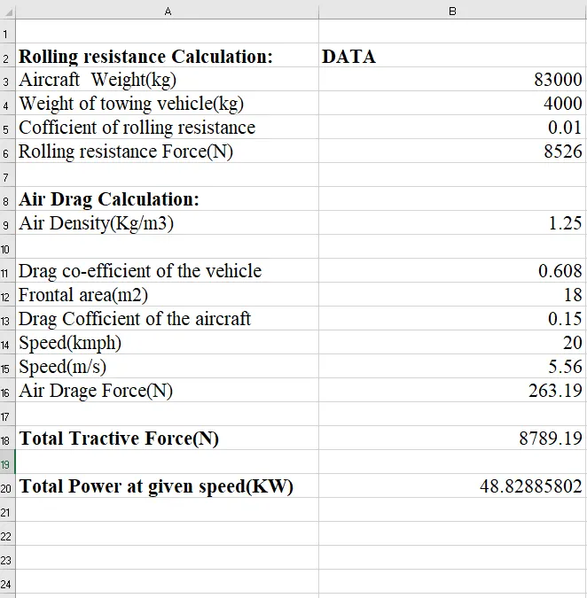
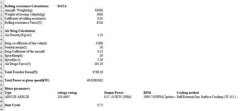
Airbus A321 is considered for the calculation power and force required by the towing vehicle.The weight of airbus A321 is 83000 Kg and weight of towing vehicle is assumped to be 4000 kg.The force required by the towing vehicle is 8789.19 N and power at the speed of 20kmph is 48.82 KW.
6-b)Aim:
To develop the model for the calculated force and power using Simulink.
Model:
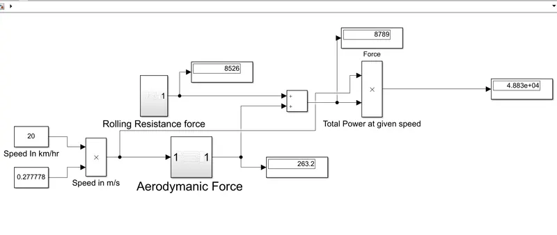
Explanation:
The rolling resistance force and aerodynamic force are modeled using subsystem block.
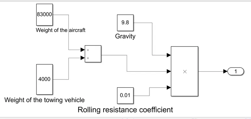
From the above figure, explain the calculation of the rolling resistance force.
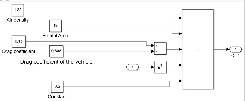
From the above figure, explain the calculation of the aerodynamic force.
Result:
For the Airbus A321, the force is 8789 N and the force at speed of 20 kmph is 48.82 KW is calculated using excel and modeled using Simulink.
7)Aim:
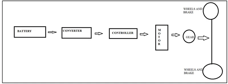
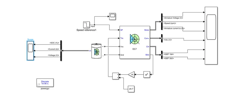
To design an electric powertrain of aircraft towing application in Simulink and estimate the duty cycle range to control the aircraft speed from zero to the highest.
Calculation:
Assumed parameters:
| Weight of aircraft | 83000 kg |
| weight of towing vehicle | 4000 kg |
| rolling resistance coefficient | 0.01 |
| Drag coefficient | 1.25 kg/m3 |
| Air density | 0.708 |
| Speed in kmph | 20 |
| Battery voltage | 550V |
Based on the previous calculation, the output power is 48.82KW. The IE2 EFFICIENCY 3-PHASE INDUCTION MOTORS type AESV2E and AESU2E are chosen for the calculation of the duty cycle.
Specification:
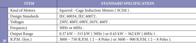
The motor output is 0.37 KW to 315 KW at 50Hz considering 60KW as output rating as we required only 48.82KW and considering 400V and considering battery voltage as 550V
The duty cycle is measured as the ratio of output voltage to the input voltage.
D=400/550=0.72
D=0.72
Block Diagram:
Model:
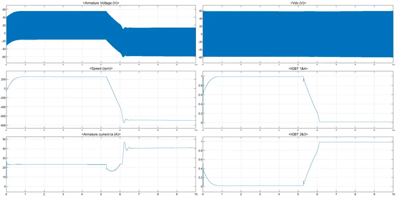
Observation:
7-b)Aim:
To design the parameters in an excel sheet.
Excel sheet:
Conclusion:
The duty cycle is calculated and the powertrain model is simulated using Simulink.